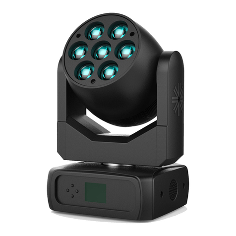
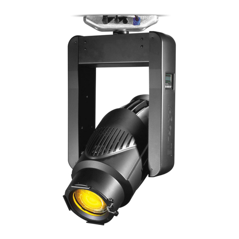
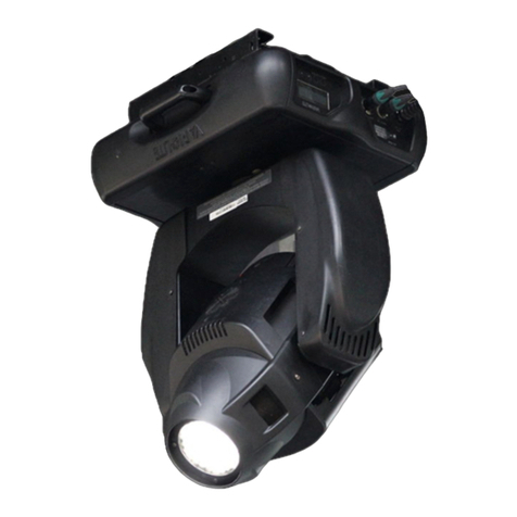
Vari Lite VL1600 Profile User manual

VL1600 ProfiLe
USER MANUAL

user manuaL
www.Vari-Lite.com
VL1600 ProfiLe
2
INTRODUCTION
OUR GOAL
We are committed to providing you the highest quality in customer service. Our comprehensive resources are
available to help your business succeed and ensure you get the full benefit of being a Vari-Lite customer.
TECHNICAL SUPPORT
Our Service and Support team is tasked with online and field support, repair, demo, commissioning, mainte-
nance contracts, and technical training for fixtures and systems. In addition, this team plays a large role in a
Systems sales, responsible for administering final commissioning, record-keeping, and organizing services. Refer
to the back cover of this user manual for contacts in your region or visit WWW.VARI-LITE.COM/SUPPORT.
CUSTOMER SERVICE
Customer Service is responsible for boxed goods and spare parts quotations, order entry and fulfilment, project
delivery, lead times, and general account management. They also manage all after sales warranty fulfilment,
RGA, and repairs invoicing in tandem with our After Sales Service & Support team. Visit our website to find a
customer service agent in your region.
ADDITIONAL DOCUMENTATION
Additional product documentation, including DMX maps, software, and photometric reports, are available for
download on our website.
For more information on installing DMX512 control systems, the following publication is available for purchase
from the United States Institute for Theatre Technology (USITT), “Recommended Practice for DMX512: A Guide
for Users and Installers, 2nd edition” (ISBN: 9780955703522).
USITT Contact Information:
USITT
315 South Crouse Avenue, Suite 200
Syracuse, New York 13210-1844 USA
Phone: 800-938-7488 or +1-315-463-6463
Fax: 866-398-7488 or +1-315-463-6525
Website: www.usitt.org
ABOUT THIS DOCUMENT
Read all instructions before installing or using this product. Retain this user manual for future reference.
Additional product information and descriptions may be found on the product data sheet(s) which can be
downloaded from the Vari-Lite website at WWW.VARI-LITE.COM.
This user manual provides necessary information regarding safety, installation, operation and routine mainte-
nance for Vari-Lite VL2600 Series. Familiarizing yourself with this information will help you to get the most out
of your product.
WARNING: It is important to read ALL accompanying safety and installation instructions to avoid damage to
the product and potential injury to yourself or others.
This user manual covers the following model(s):
• VL1600 Profile; order code(s) 88-105-7270-00, 88-105-7270-10
• ; order code(s) 88-105-6950-00, 88-105-6950-10
• ; order code(s) 88-105-7340-00, 88-105-7340-10

user manuaL
www.Vari-Lite.com
VL1600 ProfiLe
3
SAFETY WARNINGS AND NOTICES
Read this user manual in full before attempting to install, operate or maintain the fixture to which it relates. This
user manual is intended to provide general guidance to such suitably qualified personnel. Installation and opera-
tion of the fixture are to be performed by qualified personnel only.
When using electrical equipment, basic safety precautions should always be followed including the following:
READ AND FOLLOW ALL SAFETY INSTRUCTIONS.
• For indoor, dry location use only. Do not use outdoors unless fixture is suitably IP rated.
• Use safety tether when mounting.
• Equipment should be mounted in locations and at heights where it will not be readily subjected to
tampering by unauthorized personnel.
• Not for residential use. Do not use this equipment for other than intended use.
• Note distance requirement(s) from combustible materials or illuminated objects. Do not mount near gas
or electric heaters.
• Install only in locations with adequate ventilation. Ensure sure that ventilation slots are not blocked.
• Ensure that the voltage and frequency of the power supply match the power requirements of the
fixture.
• The fixture must be earthed/grounded to the appropriate conductor.
• Do not operate fixture outside the specified ambient temperature range.
• Do not connect the fixture to any dimmer pack.
• The use of accessory equipment not recommended by the manufacturer may cause an unsafe condition
and void warranty.
• Refer service to qualified personnel. This fixture contains no user serviceable parts.
• Prior to first use, carefully inspect fixture to ensure no damage has occurred during shipping.
• Materials used in the manufacturing process can cause strong odors when the product is new. These
odors dissipate over time.
• Prior to each use, carefully inspect power cables and replace any damaged cables.
• Exterior surfaces of the luminaire will be hot during operation. Take appropriate precautions.
• Continuous use of the fixture may shorten the lifespan. Power down the fixture when not in use.
• Do not cycle power on and o repeatedly. Disconnect mains power if the fixture is not used for an
extended period.
• Clean fixtures regularly, particularly when working in a dusty environment.
• Never touch power cables or wires while the fixture is powered on.
• Avoid entangling power wires with other cables.
• In the event of a serious operating problem, immediately discontinue using the fixture.
• It is hazardous to operate luminaires without lens or shield. Shields, lenses, or ultraviolet screens shall be
changed if they have become visibly damaged to such an extent that their eectiveness is impaired, for
example, by cracks or deep scratches.
• Original packing materials can be reused for transporting the fixture.
• Do not look directly at the LED light beam while the fixture is on.
• This is a Class A product. In a domestic environment this product may cause radio interference, in which
case, the user may be required to take adequate measures.
• The light source contained in this luminaire shall only be replaced by the manufacturer or service agent
or similarly qualified person.
SAVE THESE INSTRUCTIONS.
WARNING: Refer to National Electrical Code® and local codes for cable specifications. Failure to use proper
cable can result in damage to equipment or danger to personnel. Caution Against Direct Sunlight Through Front
Lens Assembly

user manuaL
www.Vari-Lite.com
VL1600 ProfiLe
4
COMPLIANCE NOTICE
FCC DECLARATION OF CONFORMITY
This equipment has been tested and found to comply with the limits for a Class A digital device pursuant to Part
15 of FCC Rules. These limits are designed to provide reasonable protection against harmful interference when
this equipment is operated in a commercial environment. This equipment generates, uses, and can radiate radio
frequency energy and, if not installed and used in accordance with Vari-Lite Strand system, service, and safety
guidelines, may cause harmful interference to radio communications.
As tested under this standard:
FCC 47CFR 15B clA*CEI
Issued:2009/10/01 Title 47 CFR Part 15 Subpart B Unintentional Radiators Class A
Operation of this equipment in a residential area is likely to cause harmful interference, in which case the user
will be required to correct the interference at his/her own expense.
EU DECLARATION OF CONFORMITY
We, Vari-Lite LLC., 10911 Petal Street, Dallas, Texas 75238, declare under our responsibility for the products
contained herein are in conformity with the essential requirements of the following European Directives and
harmonized standards:
Low Voltage Director (LVD), 2006/95/EC
EN 60589-2-17:1984+A1:1987+A2:1990 used in conjunction with 60598-1:2008/A11:2009
Electromagnetic Compatibility Directive (EMC), 2004//108/EC
EN 55022:2010, EN55024:2010

user manuaL
www.Vari-Lite.com
VL1600 ProfiLe
5
HOW TO OBTAIN WARRANTY SERVICE
A copy of the Limited Warranty card was included in the shipping package for this product.
To obtain warranty service, please contact customer service at 1-214-647-7880, or entertainment.service@
signify.com and request a Return Material Authorization (RMA) for warranty service. You will need to provide the
model and serial number of the item being returned, a description of the problem or failure and the name of the
registered user or organization. If available, you should have your sales invoice to establish the date of sale as the
beginning of the warranty period. Once you obtain the RMA, pack the unit in a secure shipping container or in its
original packing box. Be sure to clearly indicate the RMA number on all packing lists, correspondence, and ship-
ping labels. If available, please include a copy of your invoice (as proof of purchase) in the shipping container.
With the RMA number written legibly on or near the shipping address label, return the unit, freight prepaid, to:
Vari-Lite LLC
Attention: Warranty Service (RMA# ________)
10911 Petal Street
Dallas, Texas 75238
USA
As stated in the warranty, it is required that the shipment be insured and FOB our service center.
IMPORTANT! When returning products to Vari-Lite Strand for repairs (warranty or out-of-warranty) from a
country other than the USA, “Vari-Lite LLC”, must appear in the address block as the Importer of Record (IOR)
on all shipping documentation, Commercial Invoices, etc. This must be done in order to clear customs in a timely
manner and prevent returns.

user manuaL
www.Vari-Lite.com
VL1600 ProfiLe
6
FEATURES
1 DESCRIPTION
Download the product datasheet(s) from the Vari-Lite website at WWW.VARI-LITE.COM for the full technical specifications.
VL1600 PROFILE
Date:
Type:
Firm Name:
Project:
For a wide color range and maximum flexibility, the Vari-Lite VL1600
PROFILE combines a high-definition tunable white LED source with
CMY color mixing. The tunable white engine lets designers can
achieve warm and cool light from a single luminaire without
sacrificing output or CRI, along with a wide range of colors from
subtle pastels to bold saturated colors. The VL1600 PROFILE
includes the innovative Vari*frost system, giving designers a truly
seamless graduated frost that diffuses the entire aperture at one
time. This effect can be controlled remotely from the console and
doesn’t require you to change glass or add filters. To simplify startup
and minimize movement in the rig, the patented reduced-movement
calibration system in the VL1600 PROFILE calibrates pan and tilt on
the fixture while only requiring it to move to 50/50 home position
during the process. Fixtures are calibrated in less time, with less
lasting effect or potential for damage to the rig or hanging scenery.
• Precision high-output profile luminaire designed for theatre
and studio – ideal moving head fixture for precision key
lighting and special effects in the most demanding of
productions.
• CMY color mixing and fast-change fixed color wheel – A wide
color spectrum mixing both pastel and saturated colors
matched to existing Vari-Lite fixtures.
• Tunable White LED Source – achieve cold and warm looks
from the same fixture with consistently high CRI.
• Vari*frost variable frost system – Smooth frost adjustable from
edge softening to full wash diffusion without adding filters or
changing glass.
• Four frame shutter system with near-the-optics positioning –
precise framing and focus.
• Exclusive VL*FX animation wheel designed for theatre –
updated animation wheel designed to replicate natural lighting
effects such as fire, water, and earth tones.
• Limited movement calibration start up – reduce risk of the
fixture hitting set objects or shaking the rig. Minimal calibration
start-up noise.
• Adjustable frequency to exceed camera frame rates – camera
friendly fixtures for IMAG or televised events.
• Multi-mode fan control including standard, studio, whisper, and
fanless silent modes – adjust settings to control fan noise.
Offers a low dB experience across all frequencies, eliminating
buzzing or hums from an otherwise quiet device.
• Rotating gobo wheel, zoom, and iris – professional features
designed for theatrical lighting. Multiple visual options for a
variety of uses.
• Nose cone accessory mounting options – easily add
additional filters or other accessories as desired.
• Size and weight to be comparable to VL2600 PROFILE –
works easily in rigs using VL2600.
For detailed product information, please refer to the Product
Guide at www.vari-lite.com/global/products/vl1600-profile
VL1600_PROFILE

user manuaL
www.Vari-Lite.com
VL1600 ProfiLe
7
CURRENT VERSUS VOLTAGE
TABLE 1 provides the luminaire’s current draw at specific voltages. Total luminaire current is calculated with the
lamp on and all motors sequencing.
2
INSTALLATION & SETUP
POWER AND DATA CABLING REQUIREMENTS
CONNECTING POWER
This fixture requires standard AC power distribution from 100-240 VAC, 50/60 Hz. Current required depends on
the AC supply voltage.
NOTE: The mating Neutrik® powerCON® True1 connector is supplied; however, you will need to purchase or
construct a cable appropriate for your application.
Depending on the application, the luminaire’s AC input cable may require a dif-
ferent connector. If required, install a new connector meeting your requirements
using the following wire color code reference:
WARNING: DO NOT connect to three-phase service in countries with 240V power.
DATA IN
DATA
THRU
USB
NETWORK
AC
POWER
THRU
AC
POWER
INPUT
WIRE* CONNECTION
Green/yellow AC ground
Blue AC neutral
Brown AC line
* International (Harmonized) Standard
AC VOLTAGE AT 60HZ TOTAL CURRENT
100V 7.8A
110V 7.0A
120V 6.4A
130V 5.9A
200V 3.8A
210V 3.6A
220V 3.4A
230V 3.3A
240V 3.2A
TAbLE 1. CURRENT VS. VOLTAGE (550W SOURCE)
CONNECTION PIN
AC neutral X
AC line Y
Ground (earth) G
X
Y
G
CONNECTION PIN
Phase 1 X
Phase 2 Y
Ground (earth) G
For single-phase power at 240 volts RMS: For three-phase power at 200 volts RMS:
WARNING! It is the responsibility of the user to ad-
equately protect supply source with a correct size and
type circuit breaker and not overload circuits.
WARNING! It is not recommended to power any
Vari-Lite luminaire from a dimmer - even in ‘NONDIM’
mode. Dimmer and non-dim modules are not suitable
sources of power because their output modifies the AC
wave form. This may work for a short time, but will even-
tually result in power problems, luminaire misoperation
and/or failure and may void the luminaire’s warranty.

user manuaL
www.Vari-Lite.com
VL1600 ProfiLe
8
DATA CABLES
The luminaire is equipped with two, 5-pin XLR connectors for DATA IN and DATA THRU (out) applications.
DATA IN requires a 5-pin, female XLR connector and DATA THRU requires a 5-pin, male XLR connector. When
purchasing or constructing data cables, it is important that not only the correct cable type be used, but also
quality cable to ensure a reliable DMX512 system. Your cabling should meet the following USITT DMX
specification requirements:
• Suitable for use with EIA485 (RS485) operation at 250k baud
• Characteristic impedance 85-150 ohms, nominally 120 ohms
• Low capacitance
• Two twisted pairs
• Foil and braid shielded
• 24 AWG min. gauge for runs up to 1000 feet (300m)
• 22 AWG min. gauge for runs up to 1640 feet (500m)
NOTE: Microphone type cables and other general purpose, two-core audio or signal cables are not suitable for
use with DMX512.
Refer to the USITT Recommended Practice for DMX512 guide for additional information regarding DMX512
systems.
The XLR 5-pin connectors should be wired as follows:
RECOMMENDED CABLE TYPES/MANUFACTURERS
These are only a few of the suitable cable types. Any quality EIA485, twisted pair, 120 ohm, shielded cable will
also work. Refer to TABLE 2.
Pin/Wire Code to XLR Connectors
Data Thru
Cable Pinout
Male Conn.
Pin 1
Foil &
Braided
Shield
Pin 2
1st
conductor
of 1st
twisted
pair
Data (-)
Pin 3
2nd
conductor
of 1st
twisted
pair
Data (+)
Pin 4
1st
conductor
of 2nd
twisted
pair
Data (-)
Pin 5
2nd
conductor
of 2nd
twisted
pair
Data (+)
Data In
Cable Pinout
Female Conn.
1
2
3
4
51
2
3
4
5

user manuaL
www.Vari-Lite.com
VL1600 ProfiLe
9
TAbLE 2. RECOMMENDED CAbLES
TYPE PAIRS ZΩ* JACKET AWG USE TEMP (°F) TEMP (°C)
BELDEN CABLES
1215A 2150 PVC 26 IBM Type 6 Oce cable 75 24
1269A 2100 PTFE 22 (solid) High Temp, Plenum cable 200 93
8102 2100 PVC 24 UL2919 80 27
8132 2120 PVC 28 UL2919 80 27
8162 2100 PVC 24 UL2493 60 16
82729 2100 PTFE 24 High Temp, Plenum cable 200 93
88102 2100 PTFE 24 High Temp, Plenum cable 200 93
89696 2100 PTFE 22 High Temp, Plenum cable 200 93
89729 2100 PTFE 24 High Temp, Plenum cable 200 93
89855 2100 PTFE 22 High Temp, Plenum cable 200 93
9729 2100 PVC 24 UL2493 60 16
9804 2100 PVC 28 UL2960 60 16
9829 2100 PVC 24 UL2919 80 27
9842 2120 PVC 24 UL2919 80 27
PROPEX CABLES
PC224P 2110 Polyurethane 22 Heavy Duty and Portable 105 41
PC224T 2110 PVC 22 UL2464 105 41
PC226T 3110 PVC 22 UL2464
* Characteristic impedance
TERMINATION CONNECTOR
A XLR termination connector is required at the last luminaire (or “far end of the line”)
to prevent signal reflections. Signal reflections may cancel out the signal at certain line
lengths, resulting in errors. The terminator is also necessary for software downloads and
running tests on multiple luminaires. To construct your own connector, you will need the
following components:
• 5-pin, male XLR connector.
• Two 1/4W 5% 120 ohm resistors.
NOTE: A male termination connector is available as an accessory from Vari-Lite.
HANGING THE FIXTURE
The VL1600 Profile can be hung horizontally or vertically from any structure designed to work with the type
of load created by this moving luminaire. Two mounting truss hooks or other mounting hardware are required.
Many compatible truss hooks are available from dierent manufacturers for your particular needs.
A minimum of two hooks per luminaire is required. If mounting method does not use truss hooks, two attach-
ment points, per luminaire, are required.
Solder resistors across
pins 2 & 3, and 4 & 5
1
2
3
4
5

user manuaL
www.Vari-Lite.com
VL1600 ProfiLe
10
Install mounting hardware and brackets:
Step 1. Install truss hooks (also refer to “Truss Hook Hardware (by oth-
ers)” on page 23) for additional information) on two provided
truss hook brackets as required as shown in Figure 2-7.
NOTE: Various types of truss hooks can be used. The Mega Claw truss
hook (as shown in the example above) as well as many other standard
hooks, can be ordered separately.
TRUSS HOOK HARDWARE (BY OTHERS)
When installing hanging hooks on mounting brackets, Vari-Lite strongly
recommends the use of a Belleville washer when installing a truss hook or
claw. The Belleville washer’s size should be approximately 13-25mm (0.5-
1.0 in) diameter. Belleville washers are available in various thicknesses
and any of the following thicknesses are acceptable for the application
described: 0.9.mm, 1.0mm, 1.3mm, 1.9mm (0.035-inch, 0.043-inch, 0.050-
inch, 0.073-inch).
The washer serves two purposes:
• To spread out the load. When a washer IS NOT used, the bolt
head (without a washer) concentrates the load in a smaller
area, creating focused stress on the steel bracket, making premature failure possible. A steel washer is
recommended to spread this load over a larger surface area.
• To keep the bolt in place. The recommended Belleville washer maintains tension in the bolted assembly
and prevents it from vibrating loose.
If a Belleville washer is not available, a regular flat washer measuring in diameter of 25mm (1 inch) minimum can
be used in conjunction with a suitable split lock washer situated between the bolt head and flat washer.
Step 2. Determine required configuration of bracket installation. Brackets may be installed in many dierent
orientations.
Step 3. While pulling up on locking mechanism release, fit keyed holes onto raised mounting buttons at bot-
tom of enclosure. Slide forward and release locking mechanism to lock in place. Ensure brackets are
locked securely.
WARNING: Ensure that the bracket locking mechanism is fully seated after the bracket is installed on the
luminaire.
Installing in Truss:
Step 1. Using two people, lift luminaire into mounting position.
Step 2. Secure in place with truss hook. Ensure truss hook hardware that locks hook in place (e.g. wing bolt) is
properly tightened and that luminaire is fully supported.
Mount Bracket
Mega Claw
Truss Hook
(not provided)
Truss Hook Hardware
(not provided)
Press up to
Locked
install or release
Locking
Mechanism
Example Truss Hook and Mounting Hardware
(not included, sold separately)
Mount
Bracket
Locking
Mechanism
Keyed Hole
Mount Bracket
Fit bracket’s keyed hole and locking mechanism
over raised mounting buttons and slide forward
to lock.
BRACKET ORIENTATION

user manuaL
www.Vari-Lite.com
VL1600 ProfiLe
11
Step 3. Attach safety cable (as required) as follows:
a. Loop safety cable at least once around safety cable anchor point rod.
b. Loop safety cable at least once around truss/pipe and secure around pipe.
Step 4. Make sure tilt and pan locks are disengaged so luminaire moves freely.
Step 5. Connect power and data cables.
When the fixture is mounted in a side hanging orientation, you must enable side hang in the menu for proper
operation. To enable side hang, press MENU. Select CONFIG > PAN/TILT > SIDE HANG > ENABLE.
FLOOR MOUNTING
All luminaires included in this manual are designed to sit directly on its base in a floor installation application.
When used in this type of application, be sure to leave enough space around the luminaire to allow proper, unin-
terrupted airflow for cooling and movement.
CONNECTING DATA AND POWER
A maximum of 32 luminaires may be connected in any one DMX data link.
NOTE: This maximum limit applies to the luminaire “daisy chain” only. Your system or console may require few-
er luminaires on a single data link path. Consult your console documentation for more information.
To connect power and data:
Step 1. Connect data cable from console to first luminaire in chain at DATA IN connector.
Step 2. If required, connect additional data cables from DATA THRU connectors to DATA IN connectors of
remaining luminaires in link.
Step 3. At last luminaire in link, install male termination connector at DATA THRU connector. (Luminaires and
other devices on the same DMX chain may not function properly without termination.)
Step 4. Connect AC Input Cable connector to power input source.
Step 5. Dress AC input and data cables and secure them so that they will not interfere with luminaire head
and yoke movement.
POWERING UP
POWER-UP PROCEDURE
When the luminaire is powered up for the first time, the default setting is enabled and the lamp remains o.
VL1600 Profile Channel Requirements*
DMX512
Channels Description Menu Display
23 Channels 16-Bit Mode(default) 16
**DMX terminator required for last fixture on DMX line.
Data In Data Thru Data Thru
Termination**

user manuaL
www.Vari-Lite.com
VL1600 ProfiLe
12
When AC power is applied, the luminaire immediately begins a calibration sequence that steps it through full
pan and tilt movements. The internal color and beam mechanisms will also move through a full range of motion.
After calibration, the luminaire head will either stop at its “home” position (which positions the pan axis at
mid-rotation and the head parallel to the yoke with the lens pointing away from the luminaire enclosure) or
move to its current DMX-defined position if DMX data is present. All internal mechanisms also move to their
“home” or DMX-defined positions.
CAUTION: Before applying power, be sure the luminaire is hung (or positioned), and the pan and tilt locks are
disengaged, so that the head and yoke can move freely without restriction.
To power up:
Step 1. At each luminaire, apply power connecting the power cable to the unit.
Step 2. Luminaire automatically steps through calibration and stops at “home” position (only if DMX is not
present).
ADDRESSING
PROGRAM STARTING ADDRESS
The address setting for DMX console controlled systems is entered using the Menu Display. The luminaire retains
the DMX address even if power is removed.
DMX ADDRESS
To set, edit, and save a DMX address:
Step 1. Press [ESC].
Step 2. Press [Up] / [Down] arrows until Address appears. Press [OK].
Step 3. Use [Left] and [Right] arrow buttons to scroll through all digits.
Step 4. Once at desired digit, use [Up] and [Down] arrows to change highlighted digit.
Step 5. Once digit is set, use [Left] and [Right] arrow buttons to set other digits in DMX address.
Step 6. Once all digits are set in DMX address, press [OK] to set.
Step 7. DMX will display and is saved.
PROGRAM STARTING ADDRESS WITHOUT CALIBRATION
It is possible to bypass the calibration sequence and go directly to the Menu Display programming in order to
pre-program an address setting.
Program starting address without calibrating luminaire:
• While powering up luminaire, press and hold [ESC].
• When display changes from “Starting” to the DMX address, program address as in Program Starting
Address above.
NOTE: The luminaire will require a reset to restore control.
Program starting address in Battery Mode:
• To activate menu in Battery Mode when the fixture is not connected to a power source, press [OK] and
[ESC] together. The LCD screen will come on. Address the fixture as described above. The LCD screen
will shut o after one minute of inactivity.
TRANSPORTING
When shipping or transporting luminaires, Vari-Lite recommends that the luminaire(s) be suciently protected
against any (including, but not limited to) shock, vibration, drops, jarring, exposure to the environment, etc.

user manuaL
www.Vari-Lite.com
VL1600 ProfiLe
13
Failure to suciently protect any Vari-Lite luminaire during shipping or transportation will result in damage
and void the luminaire’s warranty. Vari-Lite will not be responsible for any shipping damage or breakage of any
product under any circumstances. Vari-Lite will not be responsible for any third party case manufacturer’s cases.
Note: As with all automated luminaires, proper handling and suitable protective shipping cases should be
used when transporting fixtures to reduce the risk of damage. For more information, please refer to Vari-Lite
technical notice (TN-235) “Transportation and Shipping Case Requirements” in the “Support” area of the Philips
Entertainment Lighting web site.
TRANSPORTATION AND SHIPPING CASE REQUIREMENTS
Cases to transport Vari-Lite luminaires should meet the following loading requirements:
• Luminaire head, yoke, and enclosure sub-assemblies shall be equally supported and constrained where
no one sub-assembly (head, yoke, or enclosure) fully supports the entire mass of the luminaire.
• The interior of the case shall be of high quality and uniform density foam. The foam shall be of the same
type and density throughout as to equally and uniformly support loading at every contact surface.
• The case shall, when laid on any of its six (6) surfaces, maintain the loading requirements outlined
above.
• All cases not meeting the aforementioned loading requirements, with wheels, shall have markings
on the exterior of the case that the unit is to be transported on it wheels only (e.g. “Case must be
transported and remain [at all times] on its wheels”).

user manuaL
www.Vari-Lite.com
VL1600 ProfiLe
14
VL*FX WHEEL
The eects wheel gobo wheel oers 4 images.
NOTE: VL*FX Wheel images can only be changed by an authorized service center.
COLOR WHEEL
The VL1600 Profile accomodates EasySwap color filters. EasySwap color filters can be switched out by remov-
ing the filter and inserting another one into the slot. VL1600 Profile has one EasySwap color wheel with seven
color filters and one open slot.
3 OPERATION
Carriers
Color Filter Carrier
443581625229
Color Filter Dimensions
Gobo Wheel 1
1. Leafy Breakup 2. Alpha Waves 3. Lattice 4. Night Sky
5. Swirl 6. Dust Breakup 7. Honeycomb Reverse
Eff ects Wheel
1. On the Rocks 2. Fiery Sun Prismatic 3. Triangle Breakup 4. Earth Tones
45°
R70
23.5mm
53.13mm
41mm
EasySwap Color Wheel
Carrier

user manuaL
www.Vari-Lite.com
VL1600 ProfiLe
15
GOBO WHEEL
The VL1600 Profile accomodates glass gobos. The VL1600 Profile rotating gobo wheel oers seven rotatable,
indexable gobo positions and one open position.
GOBO
SLOT
INDEX ROTATION MEGA STEPPING
DMX RANGE CENTER OF
IMAGE DMX RANGE CENTER OF
IMAGE
11 - 21 11 86 - 106 96 171 - 191 181
222 - 42 32 107 - 127 117 192 - 212 202
343 - 63 53 128 - 148 138 213 - 233 223
464 - 84 74 149 - 169 159 234 - 255 244
CAUTION: VL1600 Profile accepts glass gobos only. Use of metal gobos in these luminaires may damage gobo
assembly and will void the luminaire warranty.
GOBO DIAMETER IMAGE AREA DIAMETER GLASS THICKNESS CARRIER REQUIRED?
27mm 17.5mm 1.1mm Yes
Compatible carriers for gobos are shown below.
INSTALL OR REPLACE GOBOS
WARNING: Remove power from luminaires before performing maintenance. Gobos may be HOT after opetion.
Allow to cool before handling.
To replace a rotating gobo:
Step 1. Remove power from luminaire.
Step 2. Remove top and bottom head cover by loosening four crossed Slot screws to access the gobo wheel.
Step 3. If removing gobos via bottom of head assembly, undo fan tray assembly with thumb screw to access.
Step 4. Rotate desired gobo wheel until required gobo position is accessible.
Gobo Wheel 1
1. Leafy Breakup 2. Alpha Waves 3. Lattice 4. Night Sky
5. Swirl 6. Dust Breakup 7. Honeycomb Reverse
Eff ects Wheel
1. On the Rocks 2. Fiery Sun Prismatic 3. Triangle Breakup 4. Earth Tones
Carriers
Gobo Carrier
443581625257
Gobo Carrier with Magnet
443581625258
Carriers

user manuaL
www.Vari-Lite.com
VL1600 ProfiLe
16
CAUTION: Do not push on gobo glass. Press on gobo carrier only.
CAUTION: Do not touch gobos with bare fingers. Wear cotton gloves or other covering while replacing. To
clean, refer to CARE AND MAINTENANCE ON PAGE 35.
Step 5. Remove current gobo by carefully pressing on edges of gobo carrier with fingers, pressing gobo to-
ward front end of luminaire (toward lens), and out of wheel.
Step 6. Install new gobo as follows:
a. Place the gobo holder on a clean, flat work surface with the teeth facing upwards. The gobo is
held in place in the gobo holder by a spring. Taking care to avoid scratching or applying pressure
to the gobo, lever the end of the spring out, remove the spring and then lift the gobo out of the
gobo holder.
b. Hold the gobo with the dark side facing upwards towards the teeth in the gobo holder. Match up
the alignment marks (arrowed) in the gobo and gobo holder. Lay the new gobo flat in the gobo
holder.
c. Insert gobo carrier into wheel, ensuring that carrier snaps into place.
Step 7. Rotate desired gobo wheel until required gobo position is accessible.
DMX OPERATION
DMX MAPS
The tables assume a DMX start address of 1. When a dierent starting address is used, this address becomes
channel 1 function and other functions follow in sequence.
gobo wheel
crossed slot screw
(2 per head cover)

user manuaL
www.Vari-Lite.com
VL1600 ProfiLe
17
TAbLE 1. VL1600 PROFILE 16-bIT MODE AND 16-bIT MODE ENHANCED
DMX CHANNEL PARAMETER DEFAULTS RANGE DMX DESCRIPTION
16-BIT
ENHANCED 16-BIT
1 1 Intensity High 00-65536 16-bit control of Dimming
2 2 Intensity Low
3 3 Pan High 32768 0-65536 540° Total Pan Rotation
4 4 Pan Low
5 5 Tilt High 32768 0-65536 270° Total Tilt
6 6 Tilt Low
7 7 Focus High 32768 0-65536 Focus control
Default value 50% Focus range
8 8 Focus Low
9 9 Zoom High 32768 0-65536 Zoom control
Default value 50% zoom range
10 10 Zoom Low
11 11 Cyan 00 - 255 Cyan Color Control 0-100% saturation
12 12 Yellow 00 - 255 Yellow Color Control 0-100% saturation
13 13 Magenta 00 - 255 Magenta Color Control 0-100% saturation
14 14 Variable CCT 127 0 - 255
Variable control for Source CTO, with preset levels
3200K @ 0
7200K @ 255
15 15 Color Wheel 0
0 - 255 8-bit control of Color Wheel. (spin speed slow to fast
from control channel)
0 -16 Open Center 0
17 -47 Red Center 32
48 -79 Dark Blue Center 64
80 -111 Yellow Center 96
112 -143 Kelly Green Center 128
144 -175 Fuchsia Center 160
176 -207 Amber Center 192
208 -239 Congo Blue Center 224
240 -255 Open Center 255
16 16 Color Wheel
Control 0
0 - 5 Linear Movement using shortest (quickest) path.
6 - 10 Linear Movement using normal (longest) path.
11 - 15 Wheel Spin CW (Forward)
16 - 20 Wheel Spin STOP
21 - 25 Wheel Spin CCW (Reverse)
26 - 56 Color Shake Quickest Path (Slow to Fast) For fastest
shake set color timing to 0
57 - 87 Color Shake Normal Path (Slow to Fast) For fastest
shake set color timing to 0
88 - 255 Reserved Values

user manuaL
www.Vari-Lite.com
VL1600 ProfiLe
18
TAbLE 1. VL1600 PROFILE 16-bIT MODE AND 16-bIT MODE ENHANCED
DMX CHANNEL PARAMETER DEFAULTS RANGE DMX DESCRIPTION
16-BIT
ENHANCED 16-BIT
17 17
Color Presets
(Mixed from
CYM)
0
Preset premixed and user defined color presets
Color presets take priority over CYM & Color wheel
levels - CTO remains active
Note due to the limitations of DMX it is not possible
to fade between color presets
0 - 10 Channel o Color mixing / color wheel takes priority
11 - 14 User Preset 1
15 - 18 User Preset 2
19 - 22 User Preset 3
23 - 26 User Preset 4
27 - 30 User Preset 5
17 17
Color Presets
(Mixed from
CYM) continued
0
31 - 34 User Preset 6
35 - 38 User Preset 7
39 - 42 User Preset 8
43 - 46 User Preset 9
47 - 50 User Preset 10
51 - 54 User Preset 11
55 - 58 User Preset 12
59 - 62 User Preset 13
63 - 66 User Preset 14
67 - 70 User Preset 15
71 - 74 User Preset 16
75 - 78 User Preset 17
79 - 82 User Preset 18
83 - 86 User Preset 19
87 - 90 User Preset 20
91 - 255
Channel OFF Color Mixing takes priority. Color
presets take priority over CYM & Color wheel levels
Note due to the limitations of DMX it is not possible
to fade between color presets.

user manuaL
www.Vari-Lite.com
VL1600 ProfiLe
19
TAbLE 1. VL1600 PROFILE 16-bIT MODE AND 16-bIT MODE ENHANCED
DMX CHANNEL PARAMETER DEFAULTS RANGE DMX DESCRIPTION
16-BIT
ENHANCED 16-BIT
18 18 Gobo Wheel 1
(Rotating) 0
8-bit control of Gobo Wheel 1. See Channel 20 for
control options.
Interchangeable glass gobos
0 - 5 Open - No Gobo
6 - 10 Leafy Break up Index
11 - 15 Alpha Waves Index
16 - 20 Lattice Index
21 - 25 Night Sky Index
26 - 30 Swirl Index
31 - 35 Dust Breakup Index
36 - 40 Honeycomb Reversed Index
41 - 45 Open - No Gobo
46 - 50 Leafy Break up Rotate
51 - 55 Alpha Waves Rotate
56 - 60 Lattice Rotate
61 - 65 Night Sky Rotate
66 - 70 Swirl Rotate
71 - 75 Dust Breakup Rotate
76 - 80 Honeycomb Reverse Rotate
81 - 85 Open - No Gobo
86 - 90 Leafy Break up Mega Stepping
91 - 95 Alpha Waves Mega Stepping
96 - 100 Lattice Mega Stepping
101 - 105 Night Sky Mega Stepping
106 - 110 Swirl Mega Stepping
111 - 115 Dust Breakup Mega Stepping
116 - 120 Honeycombe Reversed Mega Stepping
121 - 255 Reserved Values
19 19 Gobo 1 Rot/
Index High Byte
32768
0 - 65536 16-bit control of index and rotation of gobo wheel 1.
0 - 32756 Rotate Fast to Slow <<<
20 20 Gobo 1 Rot/
Index Low Byte
32757 - 32780 Rotation STOP
32781 - 65536 Rotate Slow to Fast >>>

user manuaL
www.Vari-Lite.com
VL1600 ProfiLe
20
TAbLE 1. VL1600 PROFILE 16-bIT MODE AND 16-bIT MODE ENHANCED
DMX CHANNEL PARAMETER DEFAULTS RANGE DMX DESCRIPTION
16-BIT
ENHANCED 16-BIT
21 21 Gobo Wheel 1
Control 0
Used as a control channel for dierent movement
options for Gobo Wheel 1 (Channel 17)
0 - 5 Gobo Selection using shortest (quickest) path.
6 - 10 Gobo Selection using normal (longest) path.
11 - 20 Reserved Values
21 - 50 Wheel Spin CW Forward (Fast to Slow)
51 - 60 Wheel Spin STOP
61 - 90 Wheel Spin CCW Reverse (Slow to Fast)
91 - 120 Gobo Shake Quickest Path (Slow to Fast) For fastest
shake set gobo timing to 0
121 - 150 Gobo Shake Normal Path (Slow to Fast) For fastest
shake set gobo timing to 0
151 - 180 Gobo Twist Quickest Path (Slow to Fast) For fastest
twist set gobo timing to 0
181 - 210 Gobo Twist Normal Path (Slow to Fast) For fastest
twist set gobo timing to 0
211 - 255 Reserved Values
22 22 VL*FX Wheel
(Gobo Wheel 2) 0
0-255 VL*FX Wheel image selection, continuous channel
range for varied eects
0 - 0 Open No Gobo Center 0
1 - 21 On the Rocks Index Center 11
22 - 42 Fiery Sun Prismatics Index Center 32
43 - 63 Triangle Breakup Index Center 53
64 - 84 Earth Tones Index Center 74
85 - 85 Open - No Gobo Center 85
86 - 106 On the Rocks Rotation Center 96
107 - 127 Firey Sun Prismatics Rotation Center 117
128 - 148 Triangle Breakup Rotation Center 138
149 - 169 Earth Tones Rotation Center 159
170 - 170 Open No Gobo Center 170
171 - 191 On the Rocks Mega Stepping Center 181
192 - 212 Firey Sun Prismatics Mega Stepping Center 202
213 - 233 Triangle Breakup Mega Stepping Center 223
234 - 255 Earth Tones Mega Stepping Center 244
23 23
VL*FX Wheel
(Gobo Wheel 2 )
High Byte
32768
0 - 65536 16-bit control of index and rotation of gobo wheel 1.
24 24
VL*FX Wheel
(Gobo Wheel 2 )
Low Byte
0 - 32756 Rotate Fast to Slow <<<
32757 - 32780 Rotation STOP
32781 - 65536 Rotate Slow to Fast >>>
Table of contents
Other Vari Lite Light Fixture manuals
Popular Light Fixture manuals by other brands

DS Produkte
DS Produkte Z 08857 operating instructions

Westinghouse
Westinghouse Outdoor Lighting Fixture owner's manual

RSA Lighting
RSA Lighting QCT-1675BK Specification sheet

Westinghouse
Westinghouse W-181 owner's manual

SEBSON
SEBSON SET 3 R UNDER user manual

RSA Lighting
RSA Lighting Combolight LV270 Specifications

Emos
Emos ZY2146 manual

Lightolier
Lightolier SM T5 Strip specification

Philips
Philips Chicago Accessories MJ Series Specifications

SHENZHEN QIAOHUA INDUSTRIES LIMITED
SHENZHEN QIAOHUA INDUSTRIES LIMITED SL-A user manual

Cooper Lighting
Cooper Lighting Sure-Lites EUX installation instructions

Chauvet
Chauvet Legend 1200E Wash user manual