manuals.online logo
Brands
  1. Home
  2. •
  3. Brands
  4. •
  5. vatec
  6. •
  7. Plumbing Product
  8. •
  9. vatec FCP Series User manual

vatec FCP Series User manual

Schöpfdrainer Typ/
Skimmer Drainer Type FCP 50601 4
vatec-Maschinenbau GmbH · Hans-Bredow-Str. 49 ·D-28307 Bremen ·Germany
Telefon +49 (0) 421 438610 ·Telefax +49 (0) 421 4386123 ·e-mail: service@vatec.de ·www.vatec.de
1/2
Fig. 1
Verwendung:
Ableitung von fließfähigen Schwimmdecken aus Becken,
Pumpensaugkammern etc.
Application:
For the draining of free-flowing surface scum from the surface
of basins, suction chambers of pumps etc.
Funktion:
Der Schöpfdrainer ist ein Druckgefäß und wird mit der oberen
Eintrittsfläche direkt unter dem Flüssigkeitsspiegel eingebaut,
so daß nur die an der Oberfläche befindliche Flüssigkeit über
die Eintrittskante in den Druckraum des Drainers gelangen
kann.
Nach der Füllung des Drainers schließt die schwimmende
Kugel die Eintrittsöffnung.
Der Drainer wird jetzt über eine Zeitautomatik mit Druckluft
oder einem Inertgas beaufschlagt. Die in der Druckkammer
befindliche Flüssigkeit wird über das Tauchrohr in die mit
einem Rückschlagventil ausgerüstete Druckleitung gefördert.
Durch ein Regelventil kann der Gasdruck den Förderverhält-
nissen angepaßt werden.
Nach der Entleerung des Drainers wird die Kammer druck-
entlastet, so daß die Kugel öffnet und weitere Flüssigkeit in
den Drainer gelangen kann.
Fig.3 zeigt ein Installationsbeispiel mit manuellem Hubwerk
(Sonderausführung). Ebenfalls lieferbar ist eine vollautomati-
sche Ausführung.
Function:
The skimmer drainer is designed as a pressure vessel and
must be installed directly under the surface of the liquid so that
only the liquid which is on the surface can enter the pressure
vessel via the skimmer intake.
After the vessel has filled the inlet is closed by the floating ball.
The drainer is now supplied with compressed-air or inert gas,
controlled by a time switch. The liquid in the pressure chambe
r
is delivered through the dip pipe into a pressure pipe which is
equipped with a non-return valve. The gas pressure can be
adjusted to the delivery conditions by means of a control
valve.
After evacuation of the drainer, the tank is discharged from
pressure causing the skimmer ball to open which allows liquid
to flow into the drainer once more.
Fig.3 shows an installation example with manual lifting gea
r
(on special request). A fully automatic model can also be de-
livered.
Fig.2 Fig.3
vatec-Maschinenbau GmbH · Hans-Bredow-Str. 49 ·D-28307 Bremen ·Germany
Telefon +49 (0) 421 438610 ·Telefax +49 (0) 421 4386123 ·e-mail: service@vatec.de ·www.vatec.de
2/2
Komponenten:
Vertikaler Druckbehälter mit oberer Eintrittsfläche und
schwimmergesteuertem Einlaßventil, ausgerüstet mit einem
Tauchrohr und einer Druckgaszuführung.
Drainerkammer Zentrierring
Schwimmerkugel Druckgasanschluß
Ventildichtung Druckleitunganschluß
Schutzsieb Steuergerät
Components:
Vertical pressure tank with intake from above and floating ball
controlled inlet valve, equipped with dip pipe and compressed
gas inlet flange.
Drainer tank Eccentric ring
Floating ball Pressure gas connection
Valve gasket Delivery pipe connection
Protective filter Control unit
Steuerung:
Die Steuerelemente sind in einem Steuerschrank angeordnet.
Bei kontinuierlicher Abförderung erfolgt die Steuerung durch
ein Zeitprogramm mit Einschalten über EIN-AUS Taster.
Bei diskontinuierlicher Abförderung kann die Steuerung durch
ein handbetätigtes Steuerventil oder durch eine Niveausteue-
rung erfolgen (Sonderausführung).
Control:
The control elements are located in a control cabinet. Con-
tinuous delivery operation is controlled by a pre-programmed
time monitor which is operated by an on/off switch.
In cases of intermittent operation, manual control is possible
by means of a control valve or by a level controlled automatic
device (special design).
Installationshinweise:
Der Schöpfdrainer wird nach Fig. 3 vertikal eingebaut und ggf.
mit einem Gewicht gegen Auftrieb gesichert. Die Gasdruck-
zufuhr muß durch ein Sicherheitsventil so gesichert werden,
daß der Nenndruck nicht überschritten werden kann.
Bei Handbetrieb (Sonderausführung) wird das Steuerventil als
3/2-Wege-Ventil ausgeführt. Die Entlastungsleitung wird zum
Becken oberhalb des Flüssigkeitsspiegels zurückgeführt. Der
Druckstutzen des Drainers wird über ein Rückschlagventil mit
der Druckleitung verbunden.
Installation instructions:
As in Fig.3 the Skimmer Drainer must be installed vertically
and secured against buoyancy with a weight. The gas pres-
sure supply device must be equipped with a safety valve to
avoid pressure rising over the nominal level.
Where manual control is used (special design) the control
valve must be designed as a 3/2-way valve. The pressure
balance pipe is brought back to the basin above the surface
of the liquid. The drainer pressure joint is connected to the
pressure pipe by means of a non-return valve.
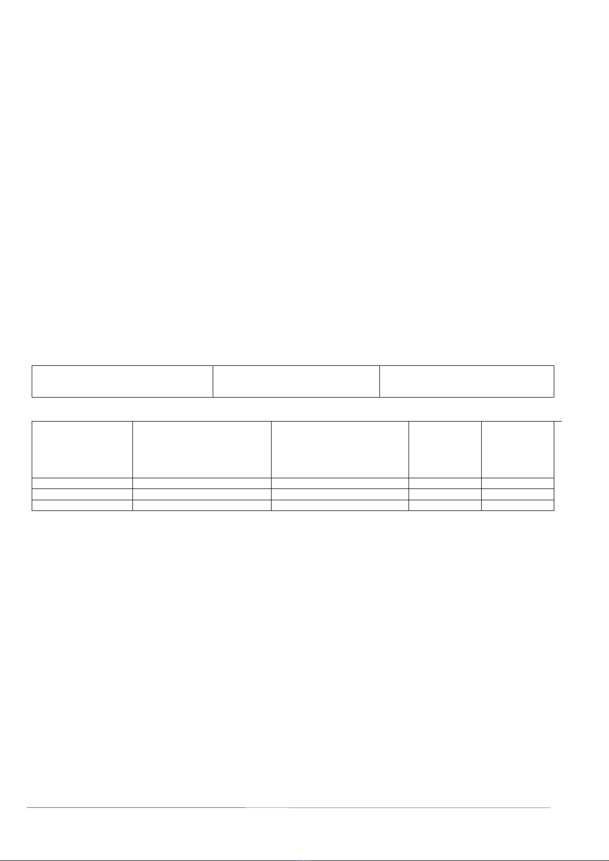
Technische Daten: Technical Datas:
Betriebsspannung
Arbeitsgas
Nenndruck
220V 50Hz
max. 10 bar
PN10
Operating voltage
Operating gas pressure
Nominal pressure
Maße: Dimensions:
AB
Druckluft/ Entlastung Druckflansch/Flanschen
Typ/Type
Compressed-air/ dearation Discharge flange/ flanges
D∅H
FCP 400 25 DIN 2501 DN 32 DIN 2501 550 715
FCP 500 32 DIN 2501 DN 40 DIN 2501 600 800
FCP 600 32 DIN 2501 DN 50 DIN 2501 800 1000
Werkstoffe:
Drainerkammer
Schwimmerkugel
Rohre
Stahl, außen beschichted
1.4571
1.4571
Materials:
Drainer vessel
Floating ball
Piping
Steel, externally coated
1.4571
1.4571
Hinweis:
Maximaler Arbeitsdruck des Gases beträgt 10 bar. Die Art des
Gases muß dem Fördermedium angepaßt sein. Bei A1-
Flüssigkeiten muß ein Inertgas verwendet werden.
Bei Flüssigkeiten, die zu Ablagerungen neigen, sollte der
Drainer während längerer Betriebspausen entleert werden.
Hierzu wird der Drainer nach der letzten Betätigung durch
Schließen eines Auslaßventils unter Druck gehalten. Hier-
durch kann keine Flüssigkeit in den Drainer eintreten.
Note:
Max. operating gas pressure must not exceed 10 bar. The kind
of gas must be adapted to the pumped medium. Inertgas must
be used where there are A1-fluids.
In case of liquids with sedimentary components the draine
r
must be kept empty during longer periods of non-operation. By
the closing of a discharge valve after last operation the draine
r
tank remains under pressure conditions a result, no fluids can
enter the drainer tank.
Sonderausführungen auf Anfrage / Änderungen vorbehalten Special design upon request / Subject to change

This manual suits for next models

3

Popular Plumbing Product manuals by other brands

Helvex MAGNA DX UE-914 installation guide

Helvex

Helvex MAGNA DX UE-914 installation guide

Billi XI Font installation guide

Billi

Billi XI Font installation guide

Omnires SYSYBI2 Installation and Maintenance

Omnires

Omnires SYSYBI2 Installation and Maintenance

Geberit HyTronic operating instructions

Geberit

Geberit HyTronic operating instructions

MEPA EasyLift 150 193 installation instructions

MEPA

MEPA EasyLift 150 193 installation instructions

KWC DOMO 20.067.733 Installation and service instructions

KWC

KWC DOMO 20.067.733 Installation and service instructions

Spectrum Brands Pfister Contempra LG49-NC1 Quick installation guide

Spectrum Brands

Spectrum Brands Pfister Contempra LG49-NC1 Quick installation guide

Grohe Atrio 34 061 manual

Grohe

Grohe Atrio 34 061 manual

Galvin Specialised CliniLever Lead Safe TM-SHWX Product installation guideline

Galvin Specialised

Galvin Specialised CliniLever Lead Safe TM-SHWX Product installation guideline

Spectrum Brands Pfister McAllen LG89-XMCA Quick installation guide

Spectrum Brands

Spectrum Brands Pfister McAllen LG89-XMCA Quick installation guide

Brizo Baliza 65005LF quick start guide

Brizo

Brizo Baliza 65005LF quick start guide

SUMERAIN S6119CP installation guide

SUMERAIN

SUMERAIN S6119CP installation guide

American Standard ARCH M968586 installation instructions

American Standard

American Standard ARCH M968586 installation instructions

Bristan CLUB VAC PBSM C MT Fitting instructions

Bristan

Bristan CLUB VAC PBSM C MT Fitting instructions

Franke CRYSTAL SEMI-PRO FFPD4600 installation manual

Franke

Franke CRYSTAL SEMI-PRO FFPD4600 installation manual

Symmons Dia 353SR-5 Operation & maintenance manual

Symmons

Symmons Dia 353SR-5 Operation & maintenance manual

Toto NEOREST MS990CG instruction manual

Toto

Toto NEOREST MS990CG instruction manual

Hans Grohe 13132000 Assembly instructions

Hans Grohe

Hans Grohe 13132000 Assembly instructions

manuals.online logo
manuals.online logoBrands
  • About & Mission
  • Contact us
  • Privacy Policy
  • Terms and Conditions

Copyright 2025 Manuals.Online. All Rights Reserved.