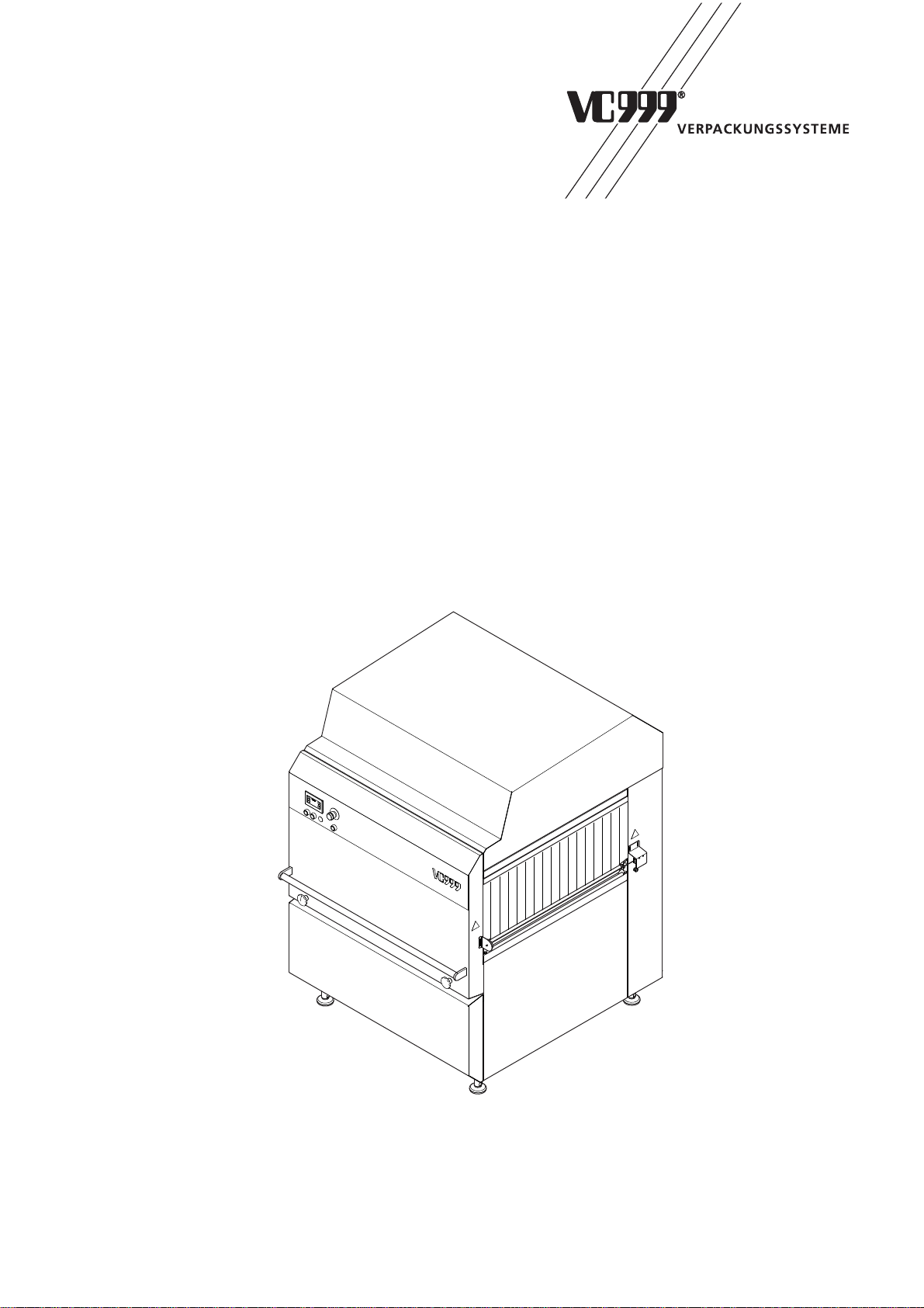
vc999 TR2 Quick guide

VC999 VERPACKUNGSSYSTEME AG
Melonenstrasse 2
CH-9100 Herisau / Schweiz
Tel. +41 (0) 71 35 35 900
Fax +41 (0) 71 35 35 901
E-Mail info@vc999.ch
TRANSLATION OF THE ORIGINAL OPERATING
INSTRUCTIONS
Art. no. 594.301
Dryer
TR2

29.11.2013
2/99
Dryer VC999 TR2
Art. No. 594.301
EC Declaration of Conformity
in accordance with the Machinery Directive 2006/42/EC
in accordance with the EMC Directive 2004/108/EC
Immunity: DIN EN 61000-6-2
Emission of interference: DIN EN 61000-6-4
Manufacturer Authorised representative
VC999 VERPACKUNGSSYSTEME AG
Melonenstrasse 2
CH-9100 Herisau
declares hereby that the following product
Product name: Dryer VC999 TR2
conforms with the relevant provisions of the
above-mentioned directives – including any valid
amendments at the time of the declaration.
The following harmonised standards have been
applied:
DIN EN ISO 12100 Safety of machinery
DIN EN 60 204-1 Electrical equipment for industrial machinery
Place: Date:
Herisau 27.11.2013
Document custodian:
Uriel Inauen
VC999 VERPACKUNGSSYSTEME AG
Melonenstrasse 2
CH-9100 Herisau

Dryer VC999 TR2
29.11.2013 3/99Art. No. 594.301
The following handover declaration must be completed by the owner. The
owner is obliged to return the original completed handover declaration to us.
The owner hereby certifies that he/she has understood and taken full note of
the operating manual. By signing this document the owner certifies that he/
sheshallobservethesafety instructions contained in the operator manualand
shall inform each and every machine user or person working on the machine
about the relevant safety instructions.
The operator shall be liable for any personal injuries or damage to property
resulting from the non-observance of the safety instructions.
Handover declaration
1. Type of machine Machine no.
2. Owner's address
3. I/we hereby declare that the machine specified under point 1 has been handed over in perfect
external condition. The instruction and training of operating personnel (including the creation
of an acceptance inspection report with documentation of the instruction/training) will be
carried out on
The person responsible for the acceptance inspection is:
If necessary, agents from the suppliers of auxiliary materials shall be consulted for accep-
tance purposes. This includes suppliers of trays, bags, films and any inert gases which may
be used. The owner is responsible for consulting these agents.
I/we hereby declare that I/we have received the operating manual with art. no. .
The contents of this manual are to be read and understood prior to commissioning and where
necessary made available to the employees authorised to work on or operate the machine. If
parts of the operating manual refer to safety at the workplace, these regulations become part
of the respective labour and service level agreements.
4. The machine has been delivered to the owner in accordance with the manufacturer's delivery
conditions. If the owner and buyer are not identical, the owner shall act on behalf of and with
the authorisation of the buyer.
5. The completed handover declaration has to be sent
to the manufacturer's address by registered mail on
the day of handover, or at the latest on the day after:
Owner's signature:
VC999 VERPACKUNGSSYSTEME AG
Melonenstrasse 2
CH-9100 Herisau / Switzerland
Supplier's signature:
Owner's stamp Date of
handover: Supplier's stamp


Dryer VC999 TR2
29.11.2013 Art. No. 594.301 5/99
Table of contents
1 Introduction ...............................................................................................................9
1.1 General information ....................................................................................................9
1.2 Terms ........................................................................................................................10
1.3 Copyright protection ..................................................................................................10
2 Safety and warranty ................................................................................................11
2.1 Explanation of the safety instructions .......................................................................11
2.1.1 Warning safety signs on the machine .......................................................................12
2.2 Residual risks ............................................................................................................13
2.3 General safety instructions .......................................................................................13
2.4 Machine stability .......................................................................................................14
2.5 Intended use .............................................................................................................14
2.6 Requirements on the operator ..................................................................................15
2.7 Warranty and liability .................................................................................................15
3 Description of the machine ....................................................................................16
3.1 Operating principle ....................................................................................................16
3.2 Structure of the machine ...........................................................................................17
3.2.1 Operator commands .................................................................................................19
3.3 Technical data ...........................................................................................................19
3.3.1 Dimensions ...............................................................................................................20
3.3.2 Weight .......................................................................................................................21
3.3.3 Products ....................................................................................................................21
3.3.4 Belt cartridge .............................................................................................................21
3.3.5 Water discharge ........................................................................................................21
3.3.6 Electrical data ...........................................................................................................21
3.3.6.1 Power supply ............................................................................................................21
3.3.6.2 Output and fuse protection ........................................................................................21
3.3.7 Controller ..................................................................................................................22
3.3.8 Noise emission ..........................................................................................................22

29.11.2013
Dryer VC999 TR2
Art. No. 594.3016/99
4 Packaging and transport ........................................................................................23
4.1 Packing the machine .................................................................................................23
4.2 Transporting the machine .........................................................................................23
4.3 Unpacking the machine ............................................................................................23
5 Setting up the machine ..........................................................................................24
5.1 Site requirements ......................................................................................................24
5.2 Foundation ................................................................................................................24
5.3 Safety clearances .....................................................................................................24
5.4 Levelling the machine ...............................................................................................25
6 Machine connections .............................................................................................26
6.1 Electrical connection .................................................................................................26
7 Installation of the machine .....................................................................................27
7.1 Electrical installation .................................................................................................28
7.2 Installation of the water discharge ............................................................................29
7.3 Installation of the protective rollers ...........................................................................29
7.4 Clean machine ..........................................................................................................30
8 Start-up ....................................................................................................................31
8.1 Initial start-up ............................................................................................................31
8.1.1 Installation check ......................................................................................................31
8.1.2 Switching on the machine .........................................................................................32
9 Operation .................................................................................................................33
9.1 General instructions ..................................................................................................33
9.2 Requirements for operation ......................................................................................33
9.3 Operation ..................................................................................................................34
9.3.1 Control panel .............................................................................................................34
9.3.2 Switching on ..............................................................................................................35
9.3.2.1 Switching on after an EMERGENCY STOP .............................................................35
9.3.3 Operation via the display ..........................................................................................36
9.3.4 Access rights .............................................................................................................38
9.4 Main menu page 1 ....................................................................................................40
9.4.1 Program parameter ...................................................................................................40
9.4.1.1 Internal conveyor belt ................................................................................................41
9.4.1.2 Blower .......................................................................................................................41
9.4.1.3 Continuous operation ................................................................................................42
9.4.1.4 Inching function Bar right ..........................................................................................42
9.4.1.5 Inching function Bar left ............................................................................................42
9.4.2 Operating hours counter ...........................................................................................43

Dryer VC999 TR2
29.11.2013 Art. No. 594.301 7/99
9.4.3 Alarm list ...................................................................................................................44
9.5 Main menu page 2 ....................................................................................................45
9.5.1 LOG IN ......................................................................................................................45
9.5.2 LOG OUT ..................................................................................................................46
9.5.3 Information ................................................................................................................46
9.5.3.1 Software versions .....................................................................................................46
9.5.3.2 Safety level ...............................................................................................................47
9.6 Main menu page 3 ....................................................................................................48
9.6.1 Machine settings .......................................................................................................48
9.6.1.1 Language, time and weekday ...................................................................................49
9.6.1.2 Further functions .......................................................................................................49
9.6.2 Inputs / Outputs .........................................................................................................53
9.7 Starting production ....................................................................................................54
9.8 Stopping production ..................................................................................................54
9.9 Continuous operation ................................................................................................54
9.10 Switching off the machine .........................................................................................54
10 Operating messages and faults .............................................................................55
10.1 Info text .....................................................................................................................55
10.2 Malfunctions ..............................................................................................................55
10.2.1 Troubleshooting ........................................................................................................56
10.2.1.1 Adjustment of lock on service door ...........................................................................57
10.2.1.2 Adjustment of the photoel. sensor on the blower system .........................................58
10.2.1.3 Throughput schematics .............................................................................................59
10.3 Error messages .........................................................................................................60
10.4 Error code servo governor ........................................................................................65
11 Maintenance ............................................................................................................66
11.1 Cleaning ....................................................................................................................67
11.1.1 Cleaning agents ........................................................................................................67
11.1.2 Cleaning work ...........................................................................................................68
11.1.3 Clean blower filter .....................................................................................................69
11.1.3.1 Clean pre-filter casing ...............................................................................................70
11.1.3.2 Clean main filter element ..........................................................................................70
11.1.4 Cleaning the belt cartridge and sieve ........................................................................71
11.1.5 Rinse water collection tray ........................................................................................73
11.2 Checks ......................................................................................................................73
11.2.1 Checking the belt tension ..........................................................................................74
11.2.2 Check belt tension on blower ....................................................................................74
11.3 Maintenance work .....................................................................................................76
11.3.1 Periodic maintenance work .......................................................................................76
11.3.1.1 Adjust belt tension on blower ....................................................................................77
11.3.1.2 Replace belts in blower .............................................................................................77
11.3.1.3 Service blower air lines .............................................................................................78
11.3.1.4 Readjustment of the headed dowel ..........................................................................78

29.11.2013
Dryer VC999 TR2
Art. No. 594.3018/99
12 Repairs .....................................................................................................................79
12.1 Repairs to the electronics or control system .............................................................79
12.1.1 Replacing fuses ........................................................................................................80
12.1.2 Replacing the display ................................................................................................80
12.1.3 Replacing the buffer battery of the PLC control system ............................................81
13 Spare parts ..............................................................................................................82
13.1 Ordering spare parts .................................................................................................82
14 Disposal ...................................................................................................................83
15 Wiring diagrams ......................................................................................................84
16 Appendix ..................................................................................................................97
16.1 Safety-related spare parts .........................................................................................97
17 Index .........................................................................................................................98

Dryer VC999 TR2
Introduction
29.11.2013 9/99Art. No. 594.301
1 Introduction
1.1 General information
This operating manual is an integral part of your machine. The information and safety instruc-
tions contained herein must be carefully read and adhered to by members of staff who are au-
thorised to operate the machine. Superiors who are responsible for machine operation shall be
liable for all damages and consequences resulting from the incorrect handling of the machine.
It is therefore in the interest of the operator that this operating manual is strictly adhered to.
The manufacturer shall not be liable for any damages which occur due to the non-observance
of this operating manual in its entirety.
An awareness of the information contained in this operating manual is essential for preventing
faults during operation and guaranteeing error-free operation. It is therefore imperative that this
operating manual is actually read and understood by members of staff authorised to operate
the machine.
This machine is a state-of-the-art device at the time of delivery. It complies with CE regulations
and the latest version of Machinery Directive 2006/42/EC at the time of delivery.
In the unlikely event that problems should occur, or if questions arise, please do not hesitate to
contact our Customer Service Department.
Due to technical changes and improvements to the machine some of the diagrams contained
in this operating manual may not be exact. However, the diagrams are sufficiently comprehen-
sive to explain processes or a course of action.
We reserve the right to make changes to the dimensions and design of the machine.
Customer service Switzerland
The manufacturer’s address is displayed on the machine's rating plate. Please always state the
machine type and serial number, which are also displayed on the rating plate, when contacting us.
Manufacturer:
Address: VC999 VERPACKUNGSSYSTEME AG
Melonenstrasse 2
CH-9100 Herisau
Represented by:
Phone:
Fax: +41 (0)71 35 35 900
+41 (0)71 35 35 901
E-mail: info@vc999.ch
www.vc999.ch

29.11.2013
10/99
Dryer VC999 TR2
Introduction
Art. No. 594.301
1.2 Terms
The following terms are used in this operating manual to describe people who work at or who are
in some way involved with the machine:
Buyer
The buyer is the person who purchases the machine from the manufacturer or its representative,
even if he/she allows a third party to use the machine. The buyer is also the manufacturer’s
customer and is the owner as defined by law.
Owner
The owner is the person who operates or uses the machine, even if he/she is not the actual owner
as defined by law. When operating the machine, the owner also assumes liability for legal risks
resulting from or connected to the operation of the machine.
Operator, operating personnel
Operators or operating personnel are the people responsible and authorised to operate the
machine. These people must be sufficiently knowledgeable in the correct handling and operation
of the machine. Usually, one or several people are given responsibility for the machine and are
provided with the operating manual for future reference.
It is expected that these people have been briefed about the machine and the operating manual
on-site, are especially aware of the safety regulations for ensuring the correct handling of the
machine and have been expressly informed about compliance with the aforesaid regulations.
Specialist, specialist personnel
Specialists are specially trained people who, due to their vocational training, are qualified to carry
out special tasks on the machine.
These people are, for example, electricians, mechanics, specialist engineers and appropriately
qualified cleaning staff. These people also have to be familiar with the contents of the operating
manual.
1.3 Copyright protection
This operating manual is confidential. All data and details contained herein are protected by copy-
right. Violations are expressly prohibited by law, and may result in severe civil and criminal penal-
ties.
This documentation contains information protected by copyright. Any reproduction, copying, scan-
ning or forwarding to third parties is expressly prohibited without the express prior permission of
VC999 VERPACKUNGSSYSTEME AG. Violators are liable for compensation.

Dryer VC999 TR2
Safety and warranty
29.11.2013 11/99Art. No. 594.301
2 Safety and warranty
2.1 Explanation of the safety instructions
All the safety instructions in this operating manual provide the operator with advance warning of
potential dangers, potential damage to the machine and the peripheral equipment, as well as error-
free, productive work.
Any sections which are of particular importance to the operator are marked with a warning symbol.
The operator must read and comply with this information.
Meanings:
DANGER
Indicates a hazardous situation which, if not avoided, will result in death or
serious injury!
WARNING
Indicates a hazardous situation which, if not avoided, could result in death or
serious injury!
CAUTION
Indicates a hazardous situation which, if not avoided, may result in minor or
moderate injury!
Indicates a situation which, if not avoided, may result in considerable damage
to equipment or the environment!

29.11.2013
12/99
Dryer VC999 TR2
Safety and warranty
Art. No. 594.301
2.1.1 Warning safety signs on the machine
All possible areas of danger are described in this operator manual and are additionally indicated
on the machine by warning safety symbols or signs. Please always pay attention to this safety infor-
mation and act with corresponding caution.
WARNING: POTENTIAL DANGER ZONE
This warning safety sign indicates potential danger zones on the machine,
which could cause injuries if not avoided. These danger zones are described
in detail in the operator manual.
WARNING: ELECTRICAL HAZARD
This area contains an electrical appliance. Risk of death due to electric shock
in case of direct contact with live parts! Only fully qualified electricians should
carry out work on electrical appliances.
WARNING: FINGER TRAP
This warning safety sign indicates a potential risk of fingers being trapped in
this area! Non-observance and reaching into the machine may result in
serious physical injuries.

Dryer VC999 TR2
Safety and warranty
29.11.2013 13/99Art. No. 594.301
2.2 Residual risks
Even where all precautions have been taken, residual risks still remain. Residual risks are poten-
tial, non-obvious risks. Pay particular attention to:
Trapped fingers and general injuries from uncoordinated operation.
Risk of injury from improper transport or movement of the machine.
Risk of injury to eyes through eye contact from air jet.
Risks from working on the electric equipment.
2.3 General safety instructions
Pay particular attention to the following instructions:
All persons involved with the installation, start-up, operation and servicing (inspection, mainte-
nance and repair work) of the machine at the owner’s company has to have carefully read and
understood the entire operating manual and especially chapter "2 Safety and warranty".
This machine is a state-of-the-art device at the time of delivery. The respective safety regula-
tions for machine operation have been observed.
All parts, whether self-manufactured or purchased from a component supplier, comply with
technical standards and EU regulations in accordance with Machinery Directive 2006/42/EC.
Continuous quality checks of our own and third party parts are carried out prior to assembly at
our production plant.
All safety and protective equipment are integral parts of this safety concept, which is geared
towards protecting all the people who are employed to work on or with this machine against
dangers.
Technical modifications affecting the functionality and effectiveness of the
safetydevices,safetyswitchesandcoversorcasingareexpresslyprohibited.
If any of the safety and protective devices are either entirely or partially put out
of service, claims for recourse against the manufacturer shall not be
accepted. The machine is then considered unsafe for operation as defined by
law and should neither be operated nor given to third parties for operation.
WARNING
Electrical hazard! Danger of death - electric shock! If the operator manual
expressly states that the power supply must be disconnected prior to certain
tasks on the machine, specifically:
The power supply must be interrupted either by disconnecting the ma-
chine from the mains or by disconnecting the plug,
or:
The main switch has to be protected from being accidentally switched on.
This can be done using a padlock or by applying a seal through the holes
provided in the switch.

29.11.2013
14/99
Dryer VC999 TR2
Safety and warranty
Art. No. 594.301
This operating manual is an integral part of your machine. If it is lost or damaged, immediately
order a replacement copy from our Customer Service Department. When doing so it is neces-
sary to state the type of machine and the machine number (according to the data on the rating
plate).
2.4 Machine stability
Machine stability is guaranteed on a flat surface if the machine is standing correctly on all 4 feet
and is levelled horizontally during normal operation according to the descriptions in this operating
manual.
Stability must be guaranteed during the whole life span of the machine, in particular during trans-
port, assembly, operation,inoperative periods,disassembly, inspections and in caseofforeseeable
faults.
In these situations, the machine must be sufficiently secured against moving, tilting and falling to
prevent personal injuries as well as damage to the machine and the environment.
The owner is solely responsible for adherence to these requirements.
2.5 Intended use
This machine is a technical tool which is solely intended for packaging suitable products at your
workplace. It may only be used for the drying of packed goods from the foodstuffs category (such
as meats and sausages, cheese, etc.) and unpacked goods. Any other use is classed as unin-
tended!
The owner is responsible for the suitability, condition and characteristics of the packaging being
dried. The machine manufacturer is not responsible for the contents of the packages.
The intended purpose of the equipment does not extend to the packaging of hazardous substances
(health-threatening substances, especially those that are poisonous, caustic, moderately or highly
inflammible and explosive substances). The machine is not rated for use in areas classified as
explosive threats.
The owner is solely responsible for workplace safety and the adherence to
statutory regulations regarding machine handling.
Do not insert objects or living entities through the machine for whatever
purpose (e.g. cleaning, drying etc.)!
This machine can be dangerous if it is not used correctly and/or for its
intended purpose. Correct usage also includes compliance with the instruc-
tions for installation, operation and repair work provided by the manufacturer.

Dryer VC999 TR2
Safety and warranty
29.11.2013 15/99Art. No. 594.301
2.6 Requirements on the operator
The machine should only be operated, serviced and repaired by authorised, fully trained and qual-
ified personnel. It is the responsibility of the owner to inform operators of possible dangers. The
machine is exclusively intended for use by personal aged 14 or older.
Ensure that responsibilities with regards to assembly, operation and repairs are clearly defined and
communicated by the owner in order to guarantee that health and safety regulations are observed.
Operators are obliged to ensure that the machine is in efficient working order prior to operation and
to inform superiors immediately about any changes constituting a risk to personal safety or device
functioning.
The operator must ensure that only authorised personnel work at the machine.
2.7 Warranty and liability
The agreements and stipulations written into the contract of sale shall apply.
Allwarrantyclaims refer to thereplacement of defective materials. Furtherclaims arenotaccepted.
The warranty applies to normal operation during a working shift/day. The warranty periods are
reduced accordingly for multiple shift operation.
Warranty claims against the manufacturer are excluded if any modifications or changes, which
have not been expressly authorised by the manufacturer or agreed with the manufacturer, are
carried out on the machine or its components The same applies for commissioning without prior
written acceptance.

29.11.2013
16/99
Dryer VC999 TR2
Description of the machine
Art. No. 594.301
3 Description of the machine
3.1 Operating principle
The machine is operated via the control panel with an interactive (touchscreen) display.
Products packed and hermetically sealed in shrink bags are fed into the machine either manually
or via a belt or roller conveyor, e.g. from a VC999 packaging machine.
When the photoelectric sensor attached on the infeed side of the machine detects an incoming
product, the conveyor belt (wire mesh conveyor belt) integrated in the machine is started by the
controller. The products are transported through the machine lying on the wire mesh conveyor belt
(Also see throughput schematics Fig. 10/5 and Fig. 10/6).
The blower system is also switched on as soon as the conveyor belt is activated. This consists of
air knives that create an air jet in the machine from above and below to form an air curtain. The
overhead suspension of the upper air knife is also referred to as a bar. The products on the belt
travel through this air curtain. The dried packages are then discharged from the machine.
Various belt or roller conveyors are optionally available for feeding products into and out of the
machine.

Dryer VC999 TR2
Description of the machine
29.11.2013 17/99Art. No. 594.301
3.2 Structure of the machine
Fig. 3/1
Key:
1
2
3
4
12
10
9
6
7,8
5
14
16
24 18 19 20 21
22
17
23
15
11
13
22
1 Name plate 13 Bar (air knife) right
2 Main switch 14 Reflector
3 Warning notification 15 Strip curtain
4 Height-adjustable machine feet 16 Machine cladding, right
5 Control panel with (touchscreen) display 17 Blower
6 EMERGENCY STOP button 18 Photoel. sensor
7 Belt cartridge (internal conveyor belt) 19 Water discharge
with wire mesh conveyor belt and 2 protective rollers 20 Access cover
8 Sieve 21 Electric cabinet
9 Star knob 22 Power cord feedthrough
10 Bar handle 23 Interior cover
11 Bar (air knife) left 24 Machine cladding, left
12 Service door, swivel-mounted

29.11.2013
18/99
Dryer VC999 TR2
Description of the machine
Art. No. 594.301
Casing
The casing consists of a robust, stainless steel structure. The machine stands on four height-
adjustable feet (4). It is fitted at the front with an upward opening service door (12). The belt
cartridge (7) with the internal conveyor belt is located behind the service door. The product infeed
and outfeed openings are equipped with a strip curtain (15).
The electrical cabinet (21) is mounted on the rear of the machine. The access cover (20), to the left
of the electric cabinet, can be removed for maintenance work.
The name plate (1) is also attached on the left of the machine.
Interfaces
Electrical connection:
The power cord can be routed into the electric cabinet (21) from the top or the bottom (22).
Water discharge:
The water discharge connection (19) is on the bottom rear of the machine's casing and is prepared
for connection with a hose with an interior diameter 30mm.
Control panel with (touchscreen) display
The machine is operated via the control panel (5) at the front of the machine. Individual parameters
can be displayed and their values edited on the touchscreen. A keyboard appears on the screen
when data must be entered. The START and STOP buttons are on the lower part of the display.
Electric cabinet
The electric cabinet (21) is accessible from the rear of the machine.
Safety devices
The machine is equipped with various safety devices. These safety devices help to protect opera-
tors against potential machine dangers. They include:
Lockable main switch (2)
EMERGENCY STOP button (6)
Belt cartridge
The belt cartridge (7) is the internal transportation unit of the product. The belt cartridge can be
accessed after opening the service door (12). The belt cartridge is fitted with a wire mesh belt and
equipped with protective rollers at both ends. This protective roller provides finger pinch protection
atthetransition point toan optional infeed / outfeed rollerconveyor.Itisalsodesigned with a certain
amount of play to prevent limbs from becoming entrapped.
When the belt cartridge is installed, it is connected to the drive motor via a mechanical coupler. The
wire mesh belt then rotates around the belt cartridge, conveying the products through the machine.
The air nozzles are integrated in the belt cartridge. A sieve (8) in the belt cartridge prevents soiling
of the belt drive. This can be pulled out during cleaning.
Infeed roller conveyor (optional)
The infeed roller conveyor (not shown) is optionally available. It can be installed and removed
without tools on both sides of the machine.

Dryer VC999 TR2
Description of the machine
29.11.2013 19/99Art. No. 594.301
Outfeed roller conveyor (optional)
The outfeed roller conveyor (not shown) is optionally available. It can be installed and removed
without tools on both sides of the machine.
3.2.1 Operator commands
One operator is required at the machine during production in order to carry out the following tasks:
To monitor and support the functional efficiency of the machine.
To actuate the EMERGENCY STOP button in an emergency situation.
3.3 Technical data
Standard scope of deliver: Available options:
Machine on 4 machine feet
Triangular socket key
Square socket key
Doubled air knife alignment on top and simple air knife
alignment on bottom
Automated,photoel.sensorcontrolledheightregulation
of the air knives
Frequency-governed intensity of the blower air volume
Frequency-governed throughput speed
Automatic and continuous operation
Digital error display
1 original copy or translation of the German
operating instructions
Outfeed roller conveyor
Infeed roller conveyor
Infeed conveyor
Outfeed conveyor

29.11.2013
20/99
Dryer VC999 TR2
Description of the machine
Art. No. 594.301
3.3.1 Dimensions
Fig. 3/2
Key:
120±50
831±50
953±50
1652
1200
904±50
1737±50
330
1869
1380
964 120
80
850
1833±50
70
602
166
90
112
888
930
90 118 154
3
4
2
3
1
1 Power cord feedthrough (top)
2 Water discharge
3 Option run-in/run-out rollers
4 Operator position
Table of contents
Popular Dryer manuals by other brands

AEG
AEG TR834S94W user manual

Whirlpool
Whirlpool WGD9250WR - Duet Cranberry - Gas Dryer installation instructions

LG
LG Steam Dryer DLEX7177SM User's guide & installation instructions

American Dryer Corp.
American Dryer Corp. ML-55 Phase 7 parts manual

Amana
Amana NED5240TQ0 parts list

Electrolux Professional
Electrolux Professional Compass Pro TD6-16 installation manual