VDH Products ALFANET PC-INTERFACE 2 Series Instructions for use

Alfanet PC-interface 2e gen.
RS 485 to RS232 or USB
With or without extra memory
Hardware user manual
Description : Alfanet PC-interface with real-time clock Doc. Nr.: 021865
Type: MANUAL Number of pages: 12 Version: V2.1
File: Do021865 Alfanet PC-Interface
RT+USB+EM v21 EN.wpd
By: RvdT Date: 09-11-2016
VDH Products BV Signed: File: Doc'02

User manual Document nr. : 021865 Version : V2.1
Alfanet PC-interface 2e gen. Client : General Page : 2 of 12
Table of contents
1. Technical specifications ..................................................... 3
2Functional specifications .................................................... 3
2.1 Installation .......................................................... 4
2.2 Control ............................................................. 4
2.3 Setting internal parameters ............................................. 4
3Program ................................................................ 5
3.1 Installation .......................................................... 5
3.1.1 RS 232 interface ................................................ 5
3.1.2 USB interface .................................................. 5
3.2 Control ............................................................. 7
4Operation of relay outputs ................................................... 8
5Front view ............................................................... 9
6Connections ............................................................ 10
7Dimensions ............................................................. 12
The information contained in this document is assumed to be accurate. However VDH Products BV accepts
no liability for eventual mistakes or errors and has the right to change this document without notice.

User manual Document nr. : 021865 Version : V2.1
Alfanet PC-interface 2e gen. Client : General Page : 3 of 12
1. Technical specifications
General
Types : ALFANET PC INTERF.2 RT+MEM
ALFANET PC INTERF.2 USB
ALFANET PC INTERF.2+ USB EM (2MB)
ALFANET PC INTERF.2+ EM (2MB)
Housing : Grey plastic housing
Material : Polystyrol 454h KG 2 natur BASF
Dimensions : 130 x 180 x 80 mm (whd)
Cable inlet : Thru turnbuckles
Cable connection : On coded screw terminals behind connection cover
Front : Polycarbonate
Supply : 230 Vac; 50/60 Hz (-10/+5%).
Used Power : 3.8 VA
Operation temperature : -20/+50EC
Store temperature : -20/+60EC
Operation rel. humidity : 10/+90 % RH not condensing
Front
Display : 4-digit display for clock with 7 day LED’s
Keys : SET key
DOWN key
UP key
LED's : Alarm (Red)
Network (Yellow)
% Percent buffer full (Green)
In- and Outputs
Relays : RY 1 : Alarm ................. (C/NO/NC 250Vac/10A not inductive)
RY 2 : LOG Buffer full .......... (C/NO/NC 250Vac/10A not inductive)
Communication : RS 485 (9600 Baud) to ALFANET (2xTwisted-pair shielded, min. 0,5mm2)
RS 232 (19200 Baud) or USB for communication to PC ...... (Modem)
Software
PC Software : V2.0.0 or higher
2Functional specifications
The Alfanet PC-Interface 2e gen. is provided with a real-time clock and display. This interface has
been developed as an intelligent interface between a Personal Computer (PC) and the RS485
network. The interface takes care of the communication between the PC and the network and is in
principle a transparent intermediary for messages from PC to the RS485 network and vice versa.
The interface can also store messages and log data in its internal buffer when the PC is not available
for communication with the interface or in case the PC is turned off.
Of all the messages coming from cool panels there are two messages to activate the relays on the
interface;
1) an alarm message to active relay 1
2) a log-buffer full message to active relay 2
The communication program for the PC requires MS Windows®.

User manual Document nr. : 021865 Version : V2.1
Alfanet PC-interface 2e gen. Client : General Page : 4 of 12
2.1 Installation
On the connection diagram of the Alfanet PC-Interface is shown how the RS485, RS232 or
USB, supply and relays must be connected.
After connecting the Alfanet PC-Interface to the power supply, a self-test function is started,
after this the current time is shown in the display.
2.2 Control
The Alfanet PC-Interface can be controlled by three pushbuttons. These buttons are:
SET - view / change value of setting.
- changing between real time and % log buffer full on the display
UP - increase value of setting / readout UTC-time.
DOWN - decrease value of setting.
2.3 Setting internal parameters
For setting the clock, summer/winter time and the log-interval there are several internal
parameters available.
To enter the internal parameter menu the DOWN key must be pressed for more than 10
seconds. In the left display the upper and lower segment are blinking. Over the UP and
DOWN keys the required parameter can be selected (see table for the parameters).
If the required parameter is selected, the value can be read-out by pushing the SET key.
Push the UP or DOWN key to change the value of this parameter.
If 20 seconds no key is pushed, the Alfanet PC-Interface changes to the normal operation
mode and the changes are stored.
Parameters ALFANET PC-INTERFACE.
PARA-
METER
DESCRIPTION PARAMETER RANGE DEFAULT
P 01
P 10
P 11
P 12
P 13
P 14
P 15
P 16
P 17
P 18
P 19
P 20
Setting clock
(See explanation)
Summer/winter time
automatic
Month start summertime
Day start summertime
Week start summertime
Time start summertime
Month start wintertime
Day start wintertime
Week start wintertime
Time start wintertime
UTC (Universal Time Coordinated) offset
Log time in UTC
hh:mm yyyy/mm/dd
0=no, 1=yes
1...12 (Jan..Dec)
0...6 (Mo..Su)
1...5 (1e, 2e, 3e, 4e, last)
0...23 (hour)
1...12 (Jan..Dec)
0...6 (Mo..Su)
1...5 (1e, 2e, 3e, 4e, last)
0...23 (hour)
-720...+720 Minutes
0=no, 1=yes
-
1
3
6
5
2
10
6
5
3
+60
0
P 30
P 31
P 32
Function Alarm relay
0 = control alarm
1 = fail save alarm
2= pulse
Function relay 2
0 = log buffer full
1 = external alarm NO
2 = external alarm NC
3 = external alarm pulse
Detection lost controller
0...2
0...3
0 = no, 1 = yes
0
0
0
P 50 Setting log interval See explanation
P 90
P 91
P 92
Software version
Serial number
Production date
-
-
-
-
-
-

User manual Document nr. : 021865 Version : V2.1
Alfanet PC-interface 2e gen. Client : General Page : 5 of 12
Explanation P01 setting clock:
After selecting parameter P 01 the clock can be set by pushing the SET key. The procedure
is as follows;
- At first the hours are set (0..23) with the UP and/or DOWN key.
- Press the SET key to confirm the value.
- Next the minutes are set (0..59) with the UP and/or DOWN key.
- Press the SET key to confirm the value.
- Next the year is set (0..9999) with the UP and/or DOWN key.
- Press the SET key to confirm the value.
- Next the month is set (1..12 = Jan..Dec) with the UP and/or DOWN key.
- Press the SET key to confirm the value.
- At last the day is set (0..6 = Mo .. Su) with the UP and/or DOWN key.
- And close the procedure by confirming the value with the SET key.
Explanation P32 detection lost controller:
If this parameter = 1, the interface will generate an alarm when the communication with one
of the controllers is lost. The interface will try to get connection with the lost controller for 5
minutes. If this failes, the alarm led and the relay will be activated. The alarm can be reset
with the SET key.
Explanation P50 setting log interval:
Normally the log intervals are set using the program on the PC. It is also possible to set the
log interval per network number without the PC. Press the SET key once after selecting
parameter P50 to set the log intervals as follows;
- The display shows ‘n 1', were the number behind the ‘n’ is network number 1.
By pressing the SET key again the log interval time is shown on the display. Value
‘0000' means off. The shown value can be changed by pressing the SET key
simultaneously with the UP or DOWN key. After releasing the keys the display
shows ‘n 1' again.
- To select an other network number use the UP and/or DOWN keys, f.i. ‘n 2'.
To change or readout the log interval time of this network number use the same
procedure as above.
At this way all log interval times of the network can be changed.
As for several seconds no key is pressed the PC-Interface returns back to it’s normal
operation.
3Program
3.1 Installation
3.1.1 RS 232 interface
Place the CD-ROM with the PC-Software in the CD-player. The installation-procedure
will start automatically. Follow the instructions during the installation.
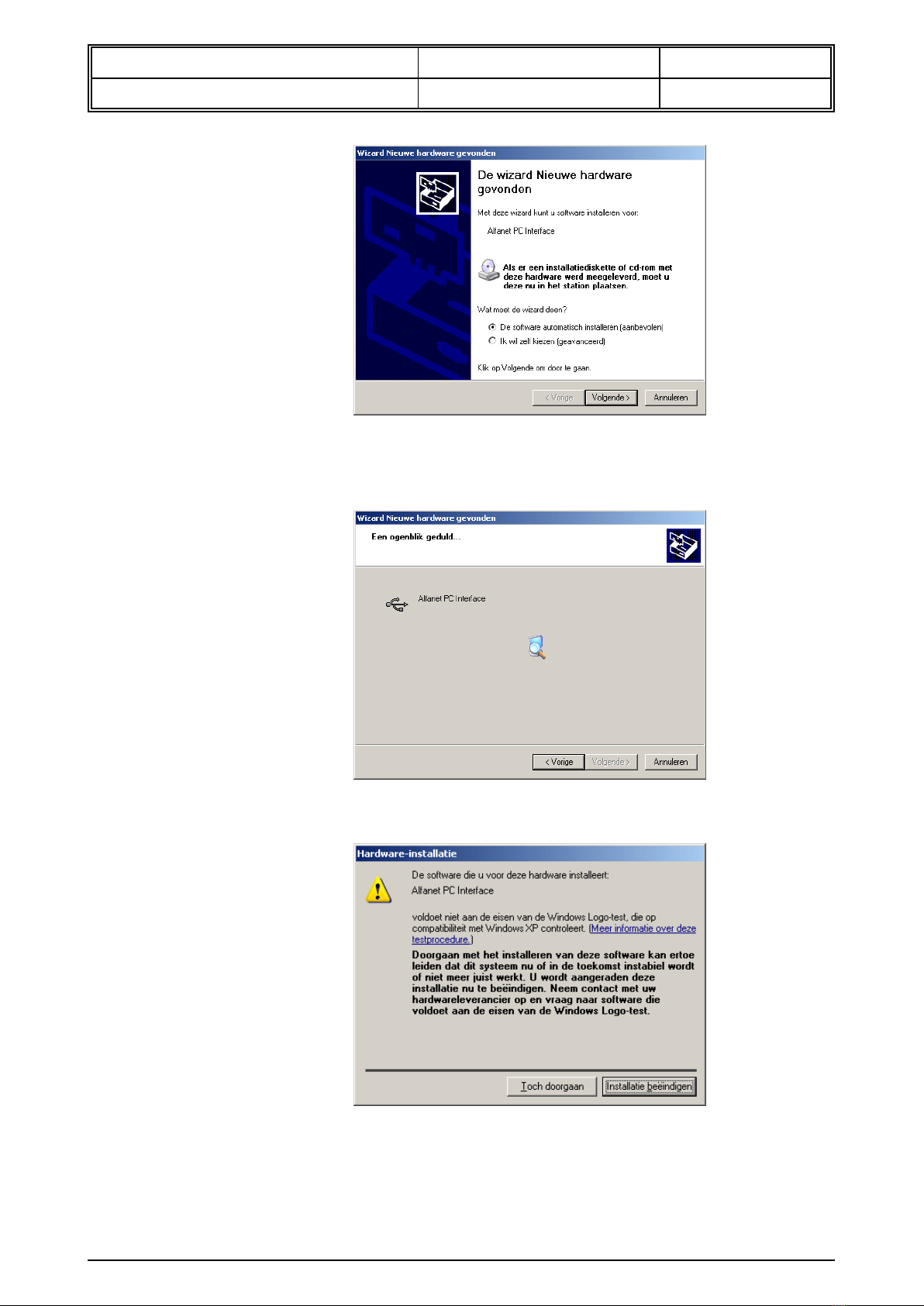
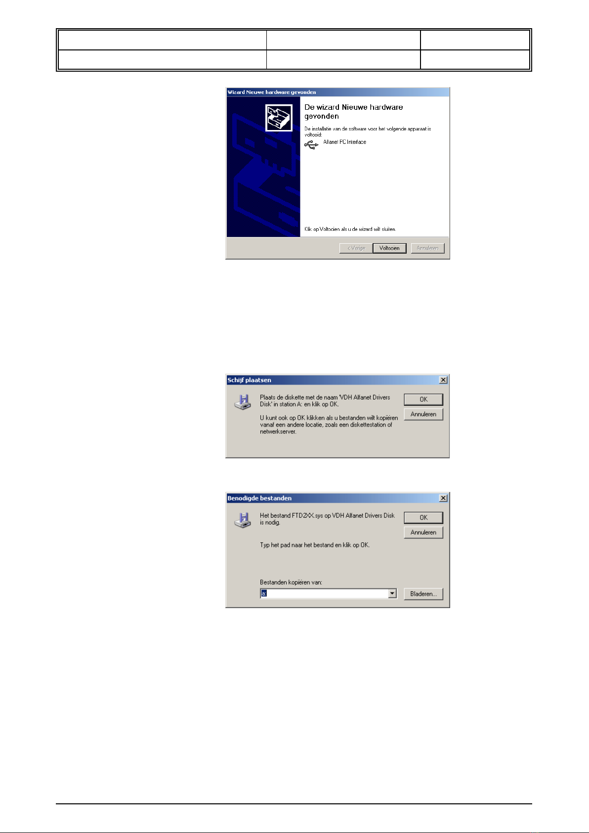
3.1.2 USB interface
Connect the USB interface to the PC before the software is been installed. As soon as
the interface is connected to the PC, Windows will give a message that it has detected
new hardware.

User manual Document nr. : 021865 Version : V2.1
Alfanet PC-interface 2e gen. Client : General Page : 6 of 12
Put the CD-ROM into the CD-player and click on “Next”.
The next screen will appear.
After that, the next screen will appear
Click on “Continue Anyway”. The software is, instead of the message, Windows
approved.
The drivers will now be installed. After the drivers have been installed, the next screen
will appear. The installation is completed.

User manual Document nr. : 021865 Version : V2.1
Alfanet PC-interface 2e gen. Client : General Page : 7 of 12
Now you can install the Alfanet program. You have to enter the CD-ROM into the CD-
player or you go to the directory “Setup” on the CD-ROM. In these directory there is a
file “setup.exe”. If you double click in the file, the installation of the Alfanet program will
start.
If the computer can not find the drivers, the next screen will appear.
Click on “OK”
On this screen you choose “Browse”
Now you have tho enter the path for the drivers. Goto the CD-ROM player. Next you go
tro the directory “driver”.
Click on “OK”. De drivers will be installed.
3.2 Control
See PC-software manual which is also available on the CD-ROM, as well as the manuals
of the ALFANET controllers.

User manual Document nr. : 021865 Version : V2.1
Alfanet PC-interface 2e gen. Client : General Page : 8 of 12
4Operation of relay outputs
The PC-Interface has two relays. All contacts are available from both relays at screw terminals.
Relay 1 The function from this relay can be adjusted with parameter P30.
A control alarm means that the relay will be energized when an alarm occurs.
A fail save alarm means that the relay is energized in normal operation an when
an alarm occurs it will be not energized if one of the connected panels on the
network has sent an alarm message.
Pulse means that the relay will be energized for 3 seconds if there is an alarm.
Relay 2 The function from this relay can be adjusted with parameter P31.
If the relay will be used as Log-buffer-full relay, the relay will be energized as one
of the connected panels on the network has sent an buffer-full message. It also will
be deactivate if the memory from the interface is full for 90%.
The function “external alarm” is for future purposes and is not active in this
moment.

User manual Document nr. : 021865 Version : V2.1
Alfanet PC-interface 2e gen. Client : General Page : 9 of 12
5Front view
* Front view Alfanet PC- Interface with RS 232, drawing 020266w4
* Frontview Alfanet PC-Interface with USB, drawing 050670w0

User manual Document nr. : 021865 Version : V2.1
Alfanet PC-interface 2e gen. Client : General Page : 10 of 12
6Connections
* Connection diagram Alfanet PC-Interface drawing 150474w1

User manual Document nr. : 021865 Version : V2.1
Alfanet PC-interface 2e gen. Client : General Page : 11 of 12
* Connection diagram Alfanet PC-Interface drawing 020976w5

User manual Document nr. : 021865 Version : V2.1
Alfanet PC-interface 2e gen. Client : General Page : 12 of 12
7Dimensions
* Dimensions Alfanet PC-Interface
@
This manual suits for next models
6
Table of contents
Popular Recording Equipment manuals by other brands

Strand
Strand Vision.net RS232 quick start guide

Roland
Roland Micro Composer MC-80 Service notes

Heritage Audio
Heritage Audio HA SUCCESSOR quick start guide

Novell
Novell LINUX ENTERPRISE 10 SP1 - LINUX AUDIT quick guide

Fostex
Fostex MTC1 owner's manual

Extron electronics
Extron electronics RGB 460xi SC Series installation guide