Vectaire WHHR Midi User guide

@@
)$*"%"%+)*%,(/
$*-*%-$(/%*%(
$)*""*%$9&(*$$$*$$
$)*(+*%$)

Page 2
@@;
>
*/%*
*)#&%(*$**%(*)$)*(+*%$$+"(+""/%($)*""$%(+)$*&(%+*7%""%-$
*)$)*(+*%$)-""$)+(**/%+(,$*"*%$)/)*#)$)*""9%##))%$$+)&(%&("/$
%$*$+)*%%&(**,"/7*(-""$%*"()&%$)"$-""$%*&*""*/%($/#;
+)*%&()%$)%(&(%&(*/*(%+"+(*%%""%-*+$&(%,$*)#$+"7*)%+"
"-/),""-**&(%+*%()/(($7
;8 5"/125mm spigot, for dwellings up to 230m2, max capacity 102 litre/sec
$("$%(#*%$
The Vectaire WHHR Midi heat recovery system provides whole house
mechanical ventilation to living areas, bedrooms, kitchen and bathrooms.
It extracts stale, contaminated air from kitchens, utility rooms and bath-
rooms, and uses the heat recovered from this air to warm fresh, incom-
ing air to create a flow of fresh, filtered air throughout the dwelling. The
extract and intake air streams are separated to avoid contamination.
The system will operate continuously to create a stable, comfortable,
healthy environment avoiding the use of excessive energy and saving
heat already generated.
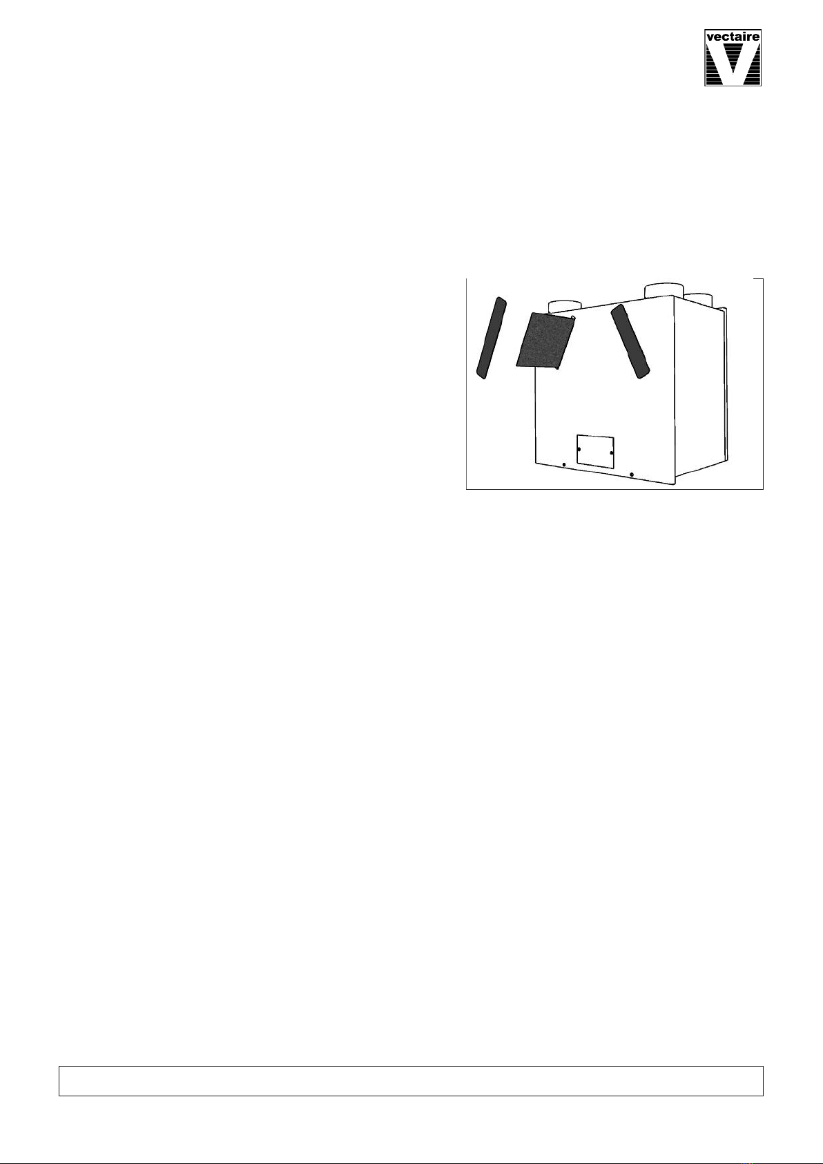
The heat recovery unit must be installed vertically, and will generally be
sited in a cupboard. It will be connected by hidden ductwork to vents
sited in the ceilings of the rooms which are to be ventilated. Each unit
is commissioned individually so that the amount of air moved is tailored
to suit the performance required. There will be a facility to boost the
extraction rate when desired (e.g when cooking or bathing, or when pol-
lutant levels rise). This may be done automatically or manually.
)/)*# ) )$ *% (+$ %$*$+%+)"/ $ )%+"
)-*%.&*%(#$*$$%("*((&"#$*7*)#&%(*$**%%""%-*,$*)+)(
#$+"$%((*"/$)*""$#$*$*)/)*#*%$)+("*/$%#%(*"$%%($,(%$#$*7
*+()
A"" whole house heat recovery units giving continuous ventilation in the kitchen and up to seven
additional wet rooms (using rigid ducting)
A low noise levels
A variable choice low (trickle) speed and boost options for optimum setting at installation
A boost speed triggered by a switched live connection from:
- a light switch (if more than one light switch is used, %$#+)*%+"&%")-*=
- DRH240 (dynamic remote humidistat)
- PIRFF (passive infra red)
- THM (thermostat)
- a remote switch/pull cord
• Economical EC motor with electronic control plus:
*$(%$*(%"*+():
B ,(" +)*#$*- trickle and boost speeds set at installation for both motors independently
B%%)*)**$ - with integral overrun timer ad ustable up to 20 minutes
B %&*%$""/;%$;*#(; boost speed does not operate if switched off within 2 minutes
B $*("(%)*;)**; proportionately reduces intake motor speed as temperature falls
Factory Set Options
B $%+*-%(!$$
B&+(%%)*- for rapid air change
B %$$*%$) - for remote motor shut off
B $*("+#)**- proportionately increases motor speeds with rising humidity
B)+##(/&))- automatic bypass of heat exchanger in hot weather
AInstallation MUST be carried out by suitably qualified personnel and MUST be in accordance with current IEE
regulations
$%#$
()(
(#
()(
%%"
%+*%$
)*"(
+*%$)*"(

$)*""*%$
AThis product should not be used for any purpose other
than that for which it was designed and as shown
in this leaflet
AAll packaging should be removed and the unit checked
for damage in transit. If there is any damage, please
contact your supplier
• The WHHR Midi must be installed vertically, and gen
erally be fitted into a cupboard, loft or ceiling void.
•$%((*%%#&"/-*%$)*(+*%$<)$>$;
#$*=+"*%$)9)+$*))%()
#$*$$<(%##$%$$$$+"))=9%(
(#%,"%""%-$$)*""*%$9&(%,%(
*)&(%+*7#$)%$)(#7
ARegulations and current Building Regulations. In order
to comply with these, it may be necessary to fit fire
dampers or other similar devices.
A "+))(%#+";+($$'+&#$*#+)*$%* (-$$*%",$(7$/(%%#(%#-(
).*(*%$*$)+"+($$&&"$9)+)$*("*$%"(9*$*)"+#+)*%*
)"%("$"+*/&9%(""%-$#+)*#%($'+*)+&&"/%($*%*(%%#7
AThe unit must be installed:
- where there is excessive oil or grease
- where there are hazardous gasses, liquids or vapours that are flammable or corrosive
- in ambient temperatures above 40ºC or lower than 0ºC
- in areas of excessive humidity or in a wet environment
• Where possible the unit should T be installed directly above a bedroom or living room.
AThe condensation drain be fitted
ACare should be taken to ensure that ducting is free from blockages
AExternal grilles should be located a minimum of 600mm from any flue outlet in accordance with all Regulations
AThe unit must be connected to a 230-240v, 50Hz single phase electrical supply.
• A triple pole isolation switch with contact separation of at least 3mm must be used to connect the appliance
to the fixed wiring when using the Switched Live.
A The product should only be connected to the mains electricity supply or electrical outlet if:
- your electrical voltage and frequency correspond to those shown on the rating label.
- the capacity of your electricity supply is sufficiently powerful to operate the product at its maximum power.
A If one of the spigots is not connected to ducting a safety grille be fitted to that spigot, so that it is
impossible for any moving part to be touched.
Installation of the appliance be carried out by a qualified and suitably competent person and should be
carried out in clean, dry conditions where dust and humidity are at minimal levels. The unit is not suitable for
installation to the exterior of the dwelling.
($)&%(**%$9&!$$)*%(&(%(*%
$)*""*%$
• Care should be taken when transporting the unit
Dropping or knocking will damage the inner workings
of the unit.
• The unit should always be stored in a clean, dry
environment.
• Remove all packaging before installation.
(;$)&*%$
• Inspect the unit and electrical supply cord for any
damage (damage must be repaired by a suitably
qualified and competent person.)
• Check all parts are supplied as shown.
Page 3

(*)")*
1 x Vectaire WHHR Midi unit.
1 x Wall mounting bracket.
1 x Safety bracket.
1 x Installation, Operation & Maintenance
Instructions
Any parts shortages or faults must be reported to the
supplier immediately.
$)*""*%$;#%+$*$
Page 4
1. Mark a horizontal line on the wall using a spirit level.
This line will be approximately 40mm below the loc-
ation of the top face of the unit when fitted (exclud-
ing duct ports). Use the mounting bracket as a
template to mark the five fixing hole centres.
2. Check fixings supplied, which are for a solid wall,
are suitable for your installation. For a different
type of mounting surface, ensure appropriate
fixings are used. Drill holes for fixings.
3. Fit wall plugs into drilled holes 4. Mount the fixing bracket to the wall ensuring the
interlocking side is at the top, as shown
5. Mount the unit by locating the bracket on the back
of the unit securely over the mounting bracket
6. Fix the lower safety bracket as shown. Screw and
plug supplied are for solid wall - check that this is
appropriate for your installation (see '2' above.)

+*$+*%$$*%$) (refer to design drawing)
A4 x 125mm nominal diameter spigots are
provided for the connection of ducting.
These are clearly marked for correct con-
nection of the supply and exhaust ducts.
AWhere ducting is installed in an +$*
space, all of the ducts should be insulated.
Where ducting is installed in a *
space, only the cold ducts should be insu-
lated. i.e. the supply duct from outside and
the extract duct from the unit to the outside.
AThe duct layout must be designed to suit
the requirements of the ventilation/heat
recovery system and building layout.
AWhere rigid duct is used, it should be
installed using the least number of fittings to minimise air flow resistance. Where possible, final connection
to the grilles and unit should be made with a flexible connection.
AWhere flexible ducts are used, ensure that:
- lengths of ducting longer than necessary are $%*used
- the duct is stretched so that it is smooth and straight
- where bends are necessary, they have large radii (ie avoid sharp bends)
- the duct is not crushed if in a restricted area
A Where ducting passes through a fire partition, suitable fire dampers #+)* be installed to prevent the
transmission of fire through the duct.
"*$
%%"
%+*%$
)*"(
.*(*
-(#9#%)*9
)*"( (#
()(
$%#$
()(
(*$
%%"
%+*%$
)*"(
.*(*
-(#9#%)*9
)*"( (#
()(
$%#$
()(
Page 5
7. %$$)*%$
A(The unit may sometimes produce condensation which must be
drained away. A 21.5/22mm dia pipe outlet is provided on this unit).
AA 21.5/22mm dia pipe must be fitted to the pipe connection. If any
part of the condensate drain is in an +$* space it be insu-
lated with the equivalent of at least 25mm of insulating material with a
thermal conductivity of 0.04 W/(mK).
AThe drain must incorporate a wet or dry trap to prevent air penetration.
AThe pipe must drain into the normal household drainage system.
($ && #+)* , %$*$+%+) "" (%# * +$* *% *
($%""*%$&%$*7
%*8%&*%$"($&%)*%$))%-$$(#9+*)*%(/**%$"/9&$$%$-*("*%((*
$#%")%((7
"*("%$$*%$
8*)&&"$)#+)*(*$""-($#+)*%$%(#*%+(($*+"*%$)$""
&&"")*$()$+"$+"*%$)7
• The unit is suitable for 230V, 50Hz Single phase supply.
• The unit is supplied with *( a mains rated 4 core flexible cord (black, brown, grey and green/yellow) %(
an external connector box.
• A triple pole isolation switch with contact separation of at least 3mm must be used to connect the appliance
to the fixed wiring when using the Switched Live.
• Boost controls must not be located within 1 metre of a cooker or where they may be affected by excessive
heat or moisture.
• Boost and other external controls should be clearly identified and conveniently located.
A Boost speed can be triggered by a switched live connection from a variety of external devices including:
- PIRFF (passive infra red)?
- DRH240 (dynamic remote humidistat)?
- THM (thermostat)?
- a light switch (if more than one light switch is used, %$#+)*%+"&%")-*=
- a remote switch/pull cord
(?PIRFF, DRH240 and THM may have integral over-run timer which controls the length of time that the fan
will continue to operate at its boost speed after the boost has been switched off.)

Page 6
%##))%$$
1. The commissioning must only be carried
out by a suitably qualified person.
2. Prior to starting the commissioning pro-
cedure, ensure that the ductwork connec
tions and airflow directions are as marked
on the product.
3. Before making any ad ustments, ensure
that the air valves or grilles are fully open.
4. Motor speed and timer settings are ad-
usted on the control board, which is lo-
cated behind the small panel on the front
of the cabinet. Once removed, there is
access to potentiometers and umper
switches for use during the commission-
ing process. (See diagram on Page 8)
8**%$*(%"%(&$"
(#%,9126,%"*",%$$*%$)(
))"7
("%- +)*#$*%(*;$($
The supply and extract motors are ad usted separately for both the normal (trickle) speed and boost speed. The
set-up procedure is as follows :-
1. For right-hand drainage as shown on Page 5, ensure that the umper switch JP4 (see diagram below)
is in %)*%$
%(#"<*(!"=&<(:($=
2. Before making any ad ustments, move the speed ad ust umper switch JP5, to position A, as shown in the
diagram. A green light will appear on the circuit board.
3. With the boost switch OFF (bathroom light switch off), measure the airflow rate at the extract valve and
compare this to the design value. If there is a difference, ad ust the potentiometer MIN-MOT2 , on the con-
trol board and re-check the airflow rate. If the value is slightly higher than that required, final ad ustment
can be made at the air valve.
4. Set the position of the potentiometer MIN-MOT1 to the same as MIN-MOT2.
5. Measure the airflow at the supply valve. This should be the same or slightly lower than the extract rate?.
If higher, reduce the airflow by ad usting MIN-MOT1. Final minor ad ustments can be made at the air valve.
?unless a different supply value has been specified.
%%)*&<(:($=
6. Switch on the boost (light switch ON).
7. Measure the airflow rate at the extract valve and compare this to the design value. If there is a difference,
ad ust the potentiometer MAX-MOT2.
8. Re-check the airflow rate and make further ad ustments at MAX-MOT2 until correct. %$%*(; +)**
(,",7
9. Set the position of the potentiometer MAX-MOT1 to the same as MAX-MOT2.
10. Measure the airflow at the supply valve. This should be the same or slightly lower than the extract rate.?
If higher, reduce the airflow by ad usting MAX-MOT1 until correct. %$%*(; +)**(,",.
?unless a different supply value has been specified.
11. Return the speed ad ust umper switch JP5, to position B (green light goes out)

Page 7
%$*(%""( +)*#$*(#
("%- +)*#$*%(*;$($
1. For left hand drainage as shown on Page 5, ensure that the umper switch JP4 (see diagram above) is in
%)*%$7
%(#"<*(!"=&<":($=
2. Before making any ad ustments, move the speed ad ust umper switch JP5, to position A, as shown in the
diagram. A green light will appear on the circuit board.
3. With the boost switch OFF (bathroom light switch off), measure the airflow rate at the extract valve and
compare this to the design value. If there is a difference, ad ust the potentiometer MIN-MOT1, on the con-
trol board and re-check the airflow rate. If the value is slightly higher than that required, final ad ustment
can be made at the air valve.
4. Set the position of the potentiometer MIN-MOT2 to the same as MIN-MOT1.
5. Measure the airflow at the supply valve. This should be the same or slightly lower than the extract rate
(
unless a different supply value has been specified
). If higher, reduce the airflow by ad usting MIN-MOT2.
Final, minor ad ustments can be made at the air valve.
%%)*&<":($=
6. Switch on the boost (light switch ON).
7. Measure the airflow rate at the extract valve and compare this to the design value. If there is a difference,
ad ust the potentiometer MAX-MOT1.
8. Re-check the airflow rate and make further ad ustments at MAX-MOT1 until correct. %$%*(; +)**
(,",7
9. Set the position of the potentiometer MAX-MOT2 to the same as MAX-MOT1.
10. Measure the airflow at the supply valve. This should be the same or slightly lower than the extract rate.?
If higher, reduce the airflow by ad usting MAX-MOT2 until correct. %$%*(; +)**(,",.
?unless a different supply value has been specified.
11. Return the speed ad ust umper switch JP5, to position B (green light goes out)
#(,((+$ +)*#$*
After the boost switch has been turned off, the fan will continue to run at boost speed for up to 20 minutes. This
overrun time is ad ustable using the potentiometer marked TIMER. The time can be varied between 0 and 20
minutes. After the set time, the fan returns to normal speed.
"/;%$%%)*
When the boost switch is operated, the boost speed activation can be delayed by 2 minutes, if required.
Using the umper switch JP6, move the umper position to either:-
- 2 minutes, or
- 0.5 seconds
Finally, replace the control panel cover securely.

Page 8
"$$$$*$$
8+$*+))126)+&&"/$%$*$)(%**$#$"&(*)7
%(((/$%+*$/#$*$$%("$$%&(*%$)*#$)"*(")+&&"/)%$;
$*.
The heat exchanger within the unit should be cleaned annually.
%"$*"*()$*.$(8
The air filters and heat exchanger of the Vectaire WHHR Midi should be cleaned regularly by a suitably qualified
person (the frequency of cleaning will vary depending on the installation environment).
"*()8
A Remove the filter covers on the front panel.
A Slide out the filters by pulling out the tabs
A Clean the filters carefully using a vacuum cleaner, replace in
the slots and refit the filter covers
*.$(8
A Firstly remove filters as described above
A Remove the screws securing the front panel. Unhook the top
edge of the panel and lift off. Using the plastic strap fitted,
carefully pull out the heat exchanger
A Caution: if this is done during cold weather, the heat exchanger
may contain water. It is advisable to have a plastic bowl avail-
able to avoid spillage.
A Lightly clean the faces of the heat exchanger with a vacuum
cleaner. Replace the heat exchanger carefully, by sliding the assembly back into the cabinet.
A Replace the front cover by hooking the top edge into the slots in the cabinet and secure in place using the
screws.
AFinally, replace the filters as above.
,(+)-*(%($/%*("+)*%"$**.$(
"*(&"#$*
Filters should be replaced annually or after a maximum of 3 cleaning cycles.
Replacement filters are available from Vectaire - call us on +44(0)1494 522333 or email to [email protected]
%+"/%+,$/'+()("*$*%*)$)*(+*%$)9&")%$***
*($"&(*#$*%$60353411222
Vectaire Ltd, Lincoln Road, Cressex Business Park, Hi h Wycombe, Buckin hamshire, HP12 3RH
Tel: +44 (0)1494 522333. Fax: +44 (0)1494 522337. Email: [email protected]
WHHR Midi Ins Aug 2013 E & O.E
Table of contents
Other Vectaire Heat Pump manuals
Popular Heat Pump manuals by other brands

Kensa Heat Pumps
Kensa Heat Pumps Shoebox user manual

Carrier
Carrier CHS183-243 installation instructions

York
York SPLIT-SYSTEM YHJD18 THRU 60 Technical guide

Ferroli
Ferroli RXA-I PLUS Series user manual

DeDietrich
DeDietrich ALEZIO S V200 user guide

Freedom
Freedom RASM Series Installation and maintenance manual

Mitsubishi Electric
Mitsubishi Electric PUHZ-SW75VHA Service manual

Trane
Trane 4TWR5018E Installer's guide

ACS
ACS PASHW015-270DLE1.5 Operation and installation manual

Robur
Robur GAHP-AR Installation, use and maintenance manual

AES
AES Hydro-Pro Inverter 11 User and service manual

Carrier
Carrier Puron IP24 owner's manual