4
2 Interface
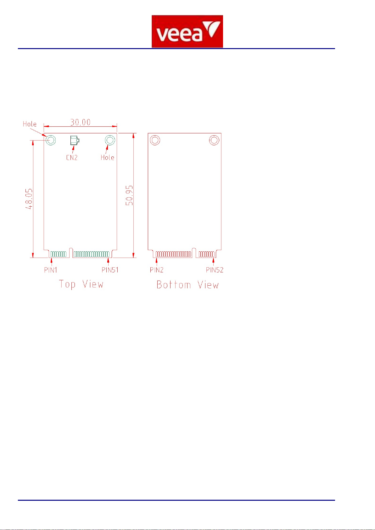
2.1 Pin definition with mini-PCIE
No
Mini PCIEx PIN
Rev.2.0
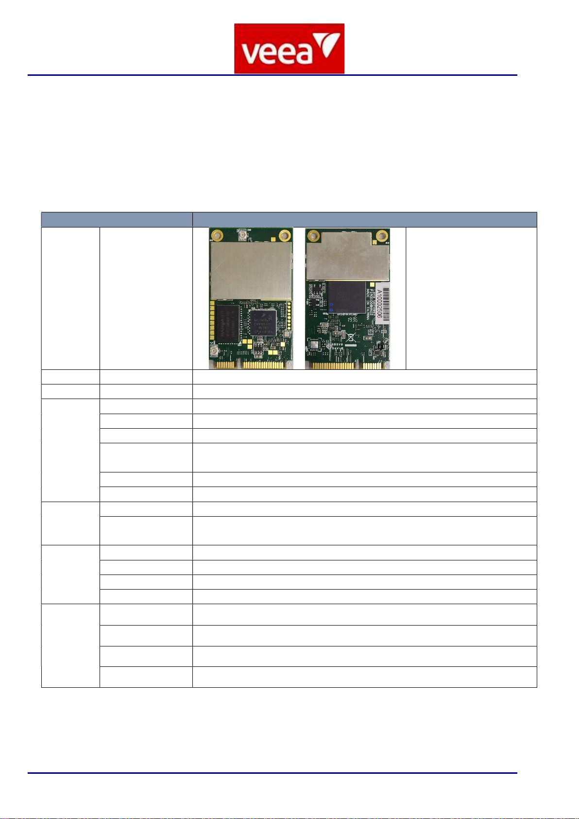
RG-1008M
PIN Power I/O Description Remarks
1 WAKE# NC N/A Internally not connected
2 3.3Vaux 3.3Vaux 3.3Vaux
N/A Supply input Connect to 3.3V
3 COEX1 NC N/A Internally not connected
4 GND GND GND N/A Ground Connect to Ground
5 COEX2 NC N/A Internally not connected
6 1.5V NC N/A Internally not connected
7 CLKREQ# NC N/A Internally not connected
8 UIM_PWR NC N/A Internally not connected
9 GND GND GND N/A Ground Connect to ground
10
UIM_DATA NC N/A Internally not connected
11
REFCLK- NC N/A Internally not connected
12
UIM_CLK NC N/A Internally not connected
13
REFCLK+ NC N/A Internally not connected
14
UIM_RESET NC N/A Internally not connected
15
GND GND GND N/A Ground Connect to ground
16
UIM_SPU NC N/A Internally not connected
17
UIM_IC_DM NC N/A Internal 10K ohm pull-up
18
GND GND GND N/A Ground Connect to ground
19
N/A N/A N/A Internally not connected
20
W_DISABLE1#
N/A I/O Reserved
21
GND GND GND N/A Ground Connect to ground
22
PERST# RESET I Reset input Active low for CPU
23
PERn0 NC N/A Internally not connected
24
3.3Vaux 3.3Vaux 3.3Vaux
I Supply input Connect to 3.3V
25
PERp0 NC N/A Internally not connected
26
GND GND GND N/A Ground Connect to ground
27
GND GND GND N/A Connect to ground
28
1.5V NC N/A Internally not connected
29
GND GND GND N/A Ground Connect to ground
30
SMB_CLK UART_TX
O UART transmit data
31
PETn0 NC N/A Internally not connected
32
SMB_DATA UART_RX
I UART receive data
33
PETp0 NC N/A Internally not connected
34
GND GND GND N/A Ground Connect to ground
35
GND GND GND N/A Ground Connect to ground
36
USB_D- USB_D- USB I/O USB Data Line D-
37
GND GND GND N/A Ground Connect to ground
38
USB_D+ USB_D+ USB I/O USB Data Line D+
39
3.3Vaux 3.3Vaux 3.3Vaux
I Supply input Connect to 3.3V
40
GND GND GND N/A Ground Connect to ground