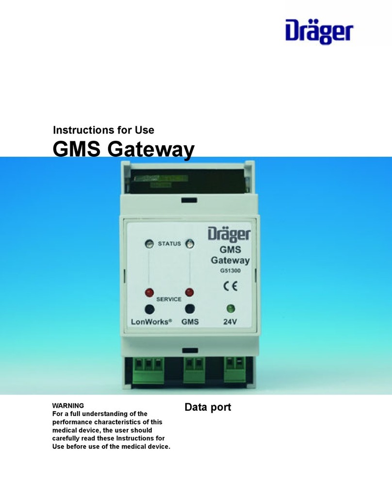
Dräger GMS-Gateway Technical manual

Gebrauchsanweisung
Montageanweisung
Instructions for Use
Installation Instructions
Alarm Monitoring System
GMS-Gateway/ GMS-Gateway VoluCount™
00138788

2
Inhaltsverzeichnis Content
Inhaltsverzeichnis
Zu Ihrer und Ihrer Patienten Sicherheit . . . . . . . . . . . . . . . . . 3
Zweckbestimmung . . . . . . . . . . . . . . . . . . . . . . . . . . . . . . . . . . 4
Was ist was . . . . . . . . . . . . . . . . . . . . . . . . . . . . . . . . . . . . . . . . . 5
Montage . . . . . . . . . . . . . . . . . . . . . . . . . . . . . . . . . . . . . . . . . . . . 6
Abnahme und Übergabe an den Betreiber . . . . . . . . . . . . . 7
LonWorks®-Interface . . . . . . . . . . . . . . . . . . . . . . . . . . . . . . . . . 8
Node Object . . . . . . . . . . . . . . . . . . . . . . . . . . . . . . . . . . . . . . . . . 9
GMS-Gateway – Data Collectors Object . . . . . . . . . . . . . . . 12
Area Control Units Object. . . . . . . . . . . . . . . . . . . . . . . . . . . . 14
GMS-Gateway VoluCount™ – Volucount Object. . . . . . . . . 19
Betrieb . . . . . . . . . . . . . . . . . . . . . . . . . . . . . . . . . . . . . . . . . . . . 22
Allgemeines. . . . . . . . . . . . . . . . . . . . . . . . . . . . . . . . . . . . . . . . 22
Service-LEDs. . . . . . . . . . . . . . . . . . . . . . . . . . . . . . . . . . . . . . . 22
Status DUO-LED der GMS-Seite . . . . . . . . . . . . . . . . . . . . . . 23
Status DUO-LED der LonWorks®-Seite . . . . . . . . . . . . . . . . 23
Aufbereiten . . . . . . . . . . . . . . . . . . . . . . . . . . . . . . . . . . . . . . . . 24
Instandhaltungsintervalle . . . . . . . . . . . . . . . . . . . . . . . . . . . . 24
Fehler – Ursache – Abhilfe . . . . . . . . . . . . . . . . . . . . . . . . . . 25
Technische Daten . . . . . . . . . . . . . . . . . . . . . . . . . . . . . . . . . . 26
Bestell-Liste . . . . . . . . . . . . . . . . . . . . . . . . . . . . . . . . . . . . . . . . 26
Stichwortverzeichnis . . . . . . . . . . . . . . . . . . . . . . . . . . . . . . . . 27
Content
For Your Safety and that of Your Patients . . . . . . . . . . . . . . 3
Intended Use . . . . . . . . . . . . . . . . . . . . . . . . . . . . . . . . . . . . . . . . 4
What's What . . . . . . . . . . . . . . . . . . . . . . . . . . . . . . . . . . . . . . . . . 5
Installation . . . . . . . . . . . . . . . . . . . . . . . . . . . . . . . . . . . . . . . . . . 6
Testing and Commissioning . . . . . . . . . . . . . . . . . . . . . . . . . . 7
LonWorks®Interface . . . . . . . . . . . . . . . . . . . . . . . . . . . . . . . . . 8
Node Object . . . . . . . . . . . . . . . . . . . . . . . . . . . . . . . . . . . . . . . . . 9
GMS Gateway – Data Collectors Object . . . . . . . . . . . . . . . 12
Area Control Units Object . . . . . . . . . . . . . . . . . . . . . . . . . . . . 14
GMS Gateway VoluCount™ – Volucount Object. . . . . . . . . 19
Operation . . . . . . . . . . . . . . . . . . . . . . . . . . . . . . . . . . . . . . . . . . 22
General . . . . . . . . . . . . . . . . . . . . . . . . . . . . . . . . . . . . . . . . . . . 22
Service LEDs. . . . . . . . . . . . . . . . . . . . . . . . . . . . . . . . . . . . . . . 22
Status DUO LED on the GMS Side . . . . . . . . . . . . . . . . . . . . 23
Status DUO LED on the LonWorks®Side . . . . . . . . . . . . . . 23
Purify . . . . . . . . . . . . . . . . . . . . . . . . . . . . . . . . . . . . . . . . . . . . . . 24
Maintenance Intervals . . . . . . . . . . . . . . . . . . . . . . . . . . . . . . . 24
Fault – Cause – Remedy . . . . . . . . . . . . . . . . . . . . . . . . . . . . 25
Technical Data . . . . . . . . . . . . . . . . . . . . . . . . . . . . . . . . . . . . . 26
Order List . . . . . . . . . . . . . . . . . . . . . . . . . . . . . . . . . . . . . . . . . 26
Index . . . . . . . . . . . . . . . . . . . . . . . . . . . . . . . . . . . . . . . . . . . . . . 27

3
Zu Ihrer und Ihrer Patienten Sicherheit For Your Safety and that of Your Patients
Zu Ihrer und Ihrer Patienten
Sicherheit
Gebrauchsanweisung/Montageanweisung beachten
Jede Handhabung an der Anlage setzt die genaue Kenntnis
und Beachtung dieser Gebrauchsanweisung/Montageanwei-
sung voraus. Die Anlage ist nur für die beschriebene Verwen-
dung bestimmt.
Instandhaltung
Die Anlage muss halbjährlich Inspektionen und Wartungen
durch Fachleute unterzogen werden (mit Protokoll).
Instandsetzungen an der Anlage nur durch Fachleute.
Für den Abschluss eines Service-Vertrags sowie für
Instandsetzungen empfehlen wir den DrägerService.
Bei Instandhaltung nur Original-Dräger-Teile verwenden.
Kapitel "Instandhaltungsintervalle" beachten..
Haftung für Funktion bzw. Schäden
Die Haftung für die Funktion der Anlage geht in jedem Fall auf
den Eigentümer oder Betreiber über, soweit die Anlage von
Personen, die nicht dem DrägerService angehören, unsach-
gemäß gewartet oder instandgesetzt wird oder wenn eine
Handhabung erfolgt, die nicht der bestimmungsgemäßen
Verwendung entspricht.
Für Schäden, die durch die Nichtbeachtung der vorstehenden
Hinweise eintreten, haftet Dräger nicht. Gewährleistungs- und
Haftungsbedingungen der Verkaufs- und Lieferbedingungen
von Dräger werden durch vorstehende Hinweise nicht
erweitert.
Dräger Medical GmbH
GEFAHR
Die Anlage ist nicht für den Betrieb in explosions-
gefährdeten Bereichen zugelassen.
For Your Safety and that of Your
Patients
Strictly follow the Instructions for Use/
Installation Instructions
Any use of the device requires full understanding and strict
observation of these instructions. The device is only to be used
for purposes specified here.
Maintenance
The device must be inspected and serviced regularly by
trained service personnel at six-monthly intervals (and a record
kept). Repair and general overhaul of the device may only be
carried out by trained service personnel.
We recommend that a service contract be obtained with
DrägerService and that all repairs also be carried out by them.
Only authentic Dräger spare parts may be used for mainte-
nance. Observe chapter "Maintenance Intervals".
Liability for proper function or damage
The liability for the proper function of the device is irrevocably
transferred to the owner or operator to the extent that the
device is serviced or repaired by personnel not employed or
authorized by DrägerService or if the device is used in a
manner not conforming to its intended use.
Dräger cannot be held responsible for damage caused by non-
compliance with the recommendations given above. The
warranty and liability provisions of the terms of sale and deli-
very of Dräger are likewise not modified by the
recommendations given above.
Dräger Medical GmbH
DANGER
This device is neither approved nor certified for use
in areas where combustible or explosive gas
mixtures are likely to occur.

4
Zweckbestimmung Intended Use
Zweckbestimmung
GMS-Gateway
Schnittstelle des Dräger Alarm Monitoring Systems zu exter-
nen Systemen mit einer LonWorks®-Schnittstelle für die Über-
tragung der Alarm- und Betriebssignale aus der zentralen
Gasversorgungsanlage auf ein Visualisierungssystem (z.B.
Gebäude-Leittechnik).
GMS-Gateway VoluCount™
Schnittstelle des Dräger Alarm Monitoring Systems zu exter-
nen Systemen mit einer LonWorks®-Schnittstelle für die Über-
tragung der Gas-Verbrauchswerte auf ein
Visualisierungssystem (z.B. Gebäude-Leittechnik).
HINWEIS
Das GMS-Gateway ist nicht zur Verwendung in
der Patientenumgebung bzw. in medizinisch
genutzten Räumen vorgesehen. Es ist nicht zur
Verwendung innerhalb der Bereichskontrollein-
heit zugelassen.
HINWEIS
Das GMS-Gateway VoluCount™ ist nicht zur Ver-
wendung in der Patientenumgebung bzw. in
medizinisch genutzten Räumen vorgesehen. Es
ist nicht zur Verwendung innerhalb der Bereichs-
kontrolleinheit zugelassen.
Intended Use
GMS Gateway
Interface of the Dräger Alarm Monitoring System to external
systems using a LonWorks®interface for transmission of
alarm and operational signals from the central gas supply
system to a visualisation system (e.g. to a building manage-
ment system).
GMS Gateway VoluCount™
Interface of the Dräger Alarm Monitoring System to external
systems using a LonWorks®interface for transmission of the
gas consumption values to a visualisation system (e.g. to a
building management system).
NOTE
The GMS gateway is not intended for use in the
patient environment or in rooms used for
medical purposes. It is not approved for use
within the area control unit.
NOTE
The GMS gateway VoluCount™ is not intended
for use in the patient environment or in rooms
used for medical purposes. It is not approved for
use within the area control unit.

5
Was ist was What's What
What's What
1Service LED, LonWorks®side
2Service LED, GMS side
3Status DUO LED, LonWorks®side
4Status DUO LED, GMS side
524 V LED
Was ist was
1Service-LED, LonWorks®-Seite
2Service-LED, GMS-Seite
3Status DUO-LED, LonWorks®-Seite
4Status DUO-LED, GMS-Seite
524-V-LED
00238788
STATUS
SERVICE
GMSLonWorks 24V
GMS
Gateway
G51300
R5
1
4
3
2

6
Montage Installation
Montage
Das GMS-Gateway und das GMS-Gateway VoluCount™ sind
als Einbaugehäuse für Hutschienenmontage ausgeführt. Die
Montage erfolgt in einem Schalt-kasten oder einem separat
erhältlichen Kunststoffgehäuse (G 50 748) durch:
●Aufklicken auf die Hutschiene (35 mm).
●Befestigung der Anschlussklemmen gemäß der Klemmen-
beschriftung.
HINWEIS
Die Schirmung des Systemkabels GM-Netzwerk
G 50 750 wird am GMS-Gateway bzw.
GMS-Gateway VoluCount™ nicht angeschlossen.
Bei Versorgung des Gerätes mittels Systemka-
bel ist sicherzustellen, dass die Schirmung am
anderen Ende des Kabels aufgelegt ist.
00338788
STATUS
SERVICE
GMSLonWorks 24V
GMS
Gateway
G51300
R
24V AC/DC
GMS
A
B
A
B
S
LonWorks
R
G 50 750
01238788
STATUS
SERVICE
GMSLonWorks 24V
GMS
Gateway
G51300
R
GMS
A
B
A
B
S
S
LonWorks
RG 50 728
G 41 784
Installation
The GMS gateway and the GMS gateway VoluCount™ are
constructed as housings for DIN rail installation. The unit is
installed in a switch box or in a separately available plastic
housing (G 50 748) by:
●Snapping onto the top hat rail (35 mm).
●Fastening of the connector terminals as labeled.
NOTE
The shielding of the G 50 750 GM network
system cable is not connected to the GMS
gateway resp. GMS gateway VoluCount™. If the
equipment is supplied via system cable, ensure
that the shielding is connected at the other end
of the cable.

7
Abnahme und Übergabe an den Betreiber Testing and Commissioning
Abnahme und Übergabe an den
Betreiber
Das GMS-Gateway und das GMS-Gateway VoluCount™ sind
Bestandteil des Dräger Alarm Monitoring Systems.
Nach Abschluss der Installation oder nach Instandhaltungs-
maßnahmen:
●Prüf- und Abnahmeprogramme durch den Sachkundigen
durchführen lassen.
Durch diese Prüfung wird sichergestellt:
— dass die sicherheitstechnischen Anforderungen zum
Schutz der Patienten und des Personals
und
— dass die Leistungsmerkmale der zentralen Versorgungsan-
lage und des Dräger Gas Managements erfüllt werden.
●Prüfergebnisse schriftlich dokumentieren.
Nach der Abnahme wird das betriebsbereite Gerät mit den
zugehörigen Unterlagen dem Betreiber übergeben und es
erfolgt die Einweisung des Bedienungspersonals.
●Übergabe protokollieren.
HINWEIS
Die Inbetriebnahme des Geräts darf erst nach
Abnahme durch sachkundiges Fachpersonal
erfolgen.
Nationale Vorschriften beachten!
Testing and Commissioning
The GMS gateway and the GMS gateway VoluCount™ are
components of the Dräger Alarm Monitoring System.
Upon completion of the installation or maintenance work:
●A test and acceptance program must be carried out by
specialists.
These tests ensure:
— that the safety requirements designed to protect patients
and staff have been met
and
— that the performance characteristics of the central gas
supply system and the Dräger Gas Management are met.
●Test results are to be documented in written form.
Following these acceptance tests, the operational device is
handed over to the user together with the documentation, and
the operating staff is instructed on how to operate the system.
●The handover procedure is to be protocolled.
NOTE
The system can only go into operation after an
acceptance test has been carried out by trained
and qualified personnel.
Note national regulations!

8
LonWorks®-Interface LonWorks®Interface
LonWorks®-Interface
GMS-Gateway
Das GMS-Gateway ist aus folgenden Objekten aufgebaut:
— Node Object (Objekt 0)
— Data Collectors Object (Objekt 1)
— Area Control Units Object (Objekt 2)
Gerätevorlagen
Für jede Interface-Variante steht eine eigene Gerätevorlage in
Form einer XIF-Datei zur Verfügung.
Variante 1 (G 51 297):
"GMS Gateway A V1_01.XIF"
(digitales Interface=Alarm)
ID 94:52:A9:46:00:09:04:02
Variante 2 (G 51 296):
"GMS Gateway AP V2_00.XIF"
(gemischt dig./analog Interface=Alarm + Pressure)
ID 94:52:A9:46:00:09:04:03
GMS-Gateway VoluCount™
Das GMS-Gateway VoluCount™ ist aus folgenden Objekten
aufgebaut:
— Node Object (Objekt 0)
— Volucount Object (Objekt 1):
Ein herstellerspezifisches Objekt der
Dräger Medical GmbH, da für die geforderte
Funktionalität kein Standard-LonMark®-Objekt zur
Verfügung steht.
Gerätevorlagen
Für das GMS-Gateway VoluCount™ steht eine Gerätevorlage
in Form einer XIF-Datei zur Verfügung.
Gerätevorlage (G 41 892):
"VC Gateway V1_00.XIF"
ID 94:52:A9:46:00:09:04:04
LonWorks®Interface
GMS Gateway
The GMS gateway is constructed using the following objects:
— Node object (object 0)
— Data collectors object (object 1)
— Area control units object (object 2)
Device Templates
For each interface version a specialised device template is
available in the form of an XIF file.
Version 1 (G 51 297):
"GMS Gateway A V1_01.XIF"
(digital interface=alarm)
ID 94:52:A9:46:00:09:04:02
Version 2 (G 51 296):
"GMS Gateway AP V2_00.XIF"
(mixed digital/analogue interface = alarm + pressure)
ID 94:52:A9:46:00:09:04:03
GMS Gateway VoluCount™
The GMS gateway VoluCount™ is constructed using the fol-
lowing objects:
— Node object (object 0)
— Volucount object (object 1):
A manufacturer-specific object of the
Dräger Medical GmbH, as there is no
standard LonMark® object available for the required
function.
Device Templates
For the GMS gateway VoluCount™ a device template is availa-
ble in the form of an XIF file.
Device template (G 41 892):
"VC Gateway V1_00.XIF"
ID 94:52:A9:46:00:09:04:04

9
LonWorks®-Interface LonWorks®Interface
Node Object Node Object
Node Object
Das Node Object dient zur Kontrolle aller Objekte im Knoten
bezüglich Selbsttests, Bereichsüberprüfungen, Fehlerkon-
trolle, File-Transfer etc.
00438788
Node Object
Object Type #0
Mandatory
Network
Variables
Optional
Network
Variables
nvoStatus
SNVT_obj_status
nv2
nviRequest
SNVT_obj_request
nv1
nvoFileDirectory
SNVT_address
nv8
Manufacturer
Defined
Section
Configuration Properties
nvoGmsState
SNVT_state
Node Object
The node object serves to monitor all objects in the node
regarding self-tests, area inspections, error control, file
transfer, etc.

10
LonWorks®-Interface LonWorks®Interface
Node Object Node Object
Vorgeschriebene Netzwerkvariablen
Mit nviRequest vom Format SNVT_obj_request ist die Anforde-
rung von Stati und Kontrolle der einzelnen Knoten-Objekte
gegeben. Dazu gehören:
— Aktivieren und Deaktivieren einzelner oder aller Knoten-
Objekte
— Anforderung des Status einzelner Knoten-Objekte
— Löschen der Statusbits aller Knoten-Objekte
— Anforderung eines Selbsttests aller Knoten-Objekte
— Anzeige von Fehler- und Alarmmeldungen der Objekte
Unterstützt werden die Requests "RQ_NORMAL",
"RQ_REPORT_MASK" und "RQ_UPDATE_STATUS" für alle
Objekte.
Mit nvoStatus vom Format SNVT_obj_status werden als Bitin-
formationen die Resultate der durch nviRequest angeforder-
ten Prüfungen und Einstellungen gemeldet.
Das Node Object unterstützt als Status "in alarm" und
"comm_failure".
Wenn die Interprozessorkommunikation der Baugruppe
gestört ist, werden auf den entsprechenden Request hin beide
Störmeldungen gesendet.
Optionale Netzwerkvariablen
Die nvoFileDirectory vom Format SNVT_address enthält die
Startadresse des Konfigurationsbereiches.
Prescribed Network Variables
A request for the status and checks of individual node objects
is available through nviRequest in the format
SNVT_obj_request. These include:
— Activation and deactivation of single or all node objects
— Status request of individual node objects
— Deletion of the status bits of all node objects
— Request for self-testing of all node objects
— Display of error and alarm messages of the objects
The requests "RQ_NORMAL", "RQ_REPORT_MASK", and
"RQ_UPDATE_STATUS" are supported for all objects.
The results of the requested tests and settings with
nviRequest are reported with nvoStatus in format
SNVT_obj_status as bit information.
The node object supports the status "in alarm" and
"comm_failure".
If the interprocessor communication of the assembly group is
interrupted, both error messages are sent after the
corresponding request.
Optional Network Variables
The nvoFileDirectory in format SNVT_address contains the
start address of the configuration area.

11
LonWorks®-Interface LonWorks®Interface
Node Object Node Object
Netzwerkvariablen im herstellerspezifischen Bereich
Im herstellerspezifischen Bereich befindet sich die Ausgangs-
variable nvoGmsState vom Format SNVT_state.
Die Bedeutung der Bits ist wie folgt:
Configuration Properties des Node Objects
Das Node Object enthält zwei Configuration Properties:
●Software-Versionen und Neuron-ID der GMS-Seite.
Hierbei handelt es sich um eine 14 Byte große Configura-
tion Property mit dem Attribut "read only", d.h. sie ist nur
lesbar, wenn das Gerät Online ist. Es handelt sich um
UCPT Type 1.
Der Aufbau dieser Configuration Property ist wie folgt:
– Software-Version der LonWorks®- Seite mit vier
Byte im Format MAJOR, MINOR,
REVISION_HIGH, REVISION_LOW
– Neuron-ID der GMS-Seite mit sechs Byte
– Software-Version der GMS-Seite mit vier Byte im
Format MAJOR, MINOR, REVISION_HIGH,
REVISION_LOW
●Eine MaxSendTime als Heartbeat für die Sendung der
Variablen nvoGmsState im Bereich von 0 bis 6.553,4 s. Die
Applikation prüft zyklisch auf Änderung dieses Konfigurati-
onsparameters. Default-Wert: 60 s
Bit Wert 0 Wert 1
0 Interkommunika-
tion der Controller
O.K.
Kommunikation
nicht möglich /
fehlerhaft
1Alle Geräte auf der
GMS-Seite können
fehlerfrei gepollt
werden
Mindestens ein
Gerät ist nicht
erreichbar
2-15 Nicht benutzt
Network Variables in the Manufacturer-specific Area
The output variable nvoGmsState in the format SNVT_state is
located in the manufacturer-specific area.
The bits are interpreted as follows:
Configuration Properties of the Node Object
The node object contains two configuration properties:
●Software versions and neuron ID of the GMS side.
This is a configuration property of 14 bytes in size, with the
"read only" attribute, i.e., it is only readable if the device is
online. This is a UCPT type 1.
This configuration property is structured as follows:
– Software version of LonWorks® side with four
bytes in the format MAJOR, MINOR,
REVISION_HIGH, REVISION_LOW
– Neuron ID of GMS side with six bytes
– Software version of GMS side with four bytes in
the format MAJOR, MINOR, REVISION_HIGH,
REVISION_LOW
●A MaxSendTime as a heartbeat for the transmission of the
nvoGmsState variables, in the range of 0 to
6,553.4 seconds. The application periodically checks for
any change to this configuration parameter. Default value:
60 seconds
Bit Value 0 Value 1
0 Intercommunica-
tion of the control-
lers is OK
Communication not
possible /
defective
1All devices on the
GMS side can be
polled without error
At least one device
is unreachable
2-15 Not used

12
LonWorks®-Interface LonWorks®Interface
GMS-Gateway – Data Collectors Object GMS Gateway – Data Collectors Object
GMS-Gateway – Data Collectors Object
Mit diesem Objekt werden die Daten von bis zu 8 GMS Daten-
sammlern dargestellt. Jeder Datensammler hat bis zu 64-Bit-
Statusinformationen, so dass die entsprechende Netzwerkva-
riable vom Format SNVT_state_64 ist.
Netzwerkvariablen des Data Collectors Objects
Es existieren ausschließlich acht Output-Variablen, welche als
Array ausgebildet sind. Der Datenpunkt von Eingang 1 eines
Datensammlers wird auf nvoDataCollect[X].bit0 dargestellt.
Bei der Änderung des Wertes einer Variablen wird diese
unmittelbar ausgesendet.
00538788
GMS Gateway
Data Collectors Object
Object Type #20100
Network
Variables
nvoDataCollect[0]
SNVT_state_64
nvoDataCollect[7]
SNVT_state_64
GMS Gateway – Data Collectors Object
This object represents the data from up to 8 GMS data
collectors. Each data collector has up to 64 bits of status
information, so that the corresponding network variable has
the format SNVT_state_64.
Network Variables for the Data Collectors Object
There are only eight output variables, structured as an array.
The data point from input 1 of a data collector is displayed in
nvoDataCollect[X].bit0.
Any change in the value of a variable is transmitted
immediately.

13
LonWorks®-Interface LonWorks®Interface
GMS-Gateway – Data Collectors Object GMS Gateway – Data Collectors Object
Configuration Properties des Data Collectors Objects
Für dieses Objekt existieren unterschiedliche Configuration
Properties, die für die Aussendung der Output-Variablen
zuständig sind:
—MaxSendTime für das Data Collectors Object
Dieser Konfigurationsparameter vom SCPT-Typ 49 ermög-
licht das zyklische Senden aller Output-Variablen des
Objektes und erspart damit die Parametrierung einer Viel-
zahl von Einzel-Heartbeats. Bei einem Wert ungleich 0 wird
nach Ablauf der parametrierten Zeit die Variable mit dem
nächst höheren Index gesendet. Wurde Index 7 versendet,
erfolgt als Nächstes die Aussendung der Variable mit dem
Index 0.
Default-Wert des Parameters: 0 s
—MaxSendTime für jede Output-Variable des Data
Collectors Objects
Wenn nicht die MaxSendTime für das Gesamt-Objekt
verwendet werden soll, steht für jede Output-Variable ein
individueller Heartbeat-Parameter ebenfalls vom SCPT-Typ
49 zur Verfügung, mit dem ein Wert zwischen 0 und
6.553,4 s parametriert werden kann.
Default-Wert für diese Parameter: 0 s
Unterstützte Alarme im Node Object
Bei einem "Test" auf dieses Objekt werden die Status "in
alarm" und "comm failure" unterstützt. Hierbei ist "in alarm"
aktiv, wenn an einer beliebigen Position der acht Output-Varia-
blen des Objekts der Wert 1 gesetzt ist.
"Comm failure" ist aktiv, wenn ein Teilnehmer im GMS nicht
mehr erreicht werden kann.
HINWEIS
Bei dieser Aussendung wird nicht berücksich-
tigt, ob eine Variable wirklich gebunden ist.
Aus diesem Grund ist die Sende-Zykluszeit
immer gleich. Ist die Zeit z.B. mit 1 s parame-
triert, erfolgt die Aussendung jeder Variablen
alle 8 s. Dies ist nur bei gebundenen Variablen
"sichtbar".
HINWEIS
Um diese individuellen Zeiten zu nutzen, muss
die MaxSendTime für das Data Collectors Object
0ssein.
Configuration Properties of the Data Collectors Object
There are different configuration properties for this object
which are responsible for the transmission of output variables:
—MaxSendTime for the Data Collectors Object
This configuration parameter from SCPT type 49 enables
the periodic transmission of all output variables, thus saving
the parametrisation of a number of individual heartbeats.
When a value is unequal to 0, the variable with the next
higher index is transmitted, after the configured time runs
out. After index 7 has been sent, the next transmission is
the variable with index 0.
Default value of the parameter: 0 seconds
—MaxSendTime for each Output Variable of the Data
Collectors Object
If MaxSendTime is not to be used for the overall object,
there is an individual heartbeat parameter available, for
each output variable, also of SCPT type 49, with a value
configurable between 0 and 6,553.4 seconds.
Default value for these parameters: 0 seconds
Alarms Supported in the Node Object
When testing this object, the status "in alarm" and
"comm failure" are supported. Here, "in alarm" is active if at any
position in the eight output variables of the object, the value 1
is set.
"Comm failure" is active if a node can no longer be reached in
GMS.
NOTE
This transmission does not take into account
whether a variable is actually bound.
For this reason, the transmission cycle time is
always the same. If the time is parameterised,
for instance, with 1 second, all variables are
then transmitted every 8 seconds. This is only
"visible" with bound variables.
NOTE
To make use of these individual times, the
MaxSendTime for the data collectors object
must be 0 seconds.

14
LonWorks®-Interface LonWorks®Interface
Area Control Units Object Area Control Units Object
Area Control Units Object
Für die Darstellung der Daten des Area Control Units Objects
stehen zwei Varianten zur Verfügung:
— Variante 1: digitale Darstellung von "Alarm"
— Variante 2: digitale und analoge Darstellung von "Alarm"
und "Pressure"
Area Control Units Object Variante 1
(Alarm, digitale Darstellung)
Mit diesem Objekt werden die digitalen Daten von bis zu 50
Area Control Units dargestellt.
Die größte Bereichskontrolleinheit kann bis zu 5 Gase aufneh-
men, so dass maximal 10 digitale Störmeldungen in Form von
High- und Low-Alarmen existieren. Aus diesem Grund haben
die Variablen vom Format SNVT_state 16 Einzelbits.
00638788
GMS Gateway
Area Control Units Object
Object Type #20110
Network
Variables
nvoAcuStates[0]
SNVT_state
nvoAcuStates[49]
SNVT_state
Configuration Properties
Area Control Units Object
To represent the data for the area control units object, there
are two versions available:
— Version 1: digital display of "Alarm"
— Version 2: digital and analogue display of "Alarm" and
"Pressure"
Area Control Units Object Version 1
(alarm, digital display)
This object is used to display the digital data of up to 50 area
control units.
The largest area control unit can accommodate up to 5 gases,
so that a maximum of 10 digital error messages, in the form of
high and low alarms are given. For this reason, the variables of
format SNVT_state have 16 individual bits.

15
LonWorks®-Interface LonWorks®Interface
Area Control Units Object Area Control Units Object
Netzwerkvariablen des Area Control Units Objects
Es existieren ausschließlich 50 Output-Variablen, welche als
Array ausgebildet sind. Der Low-Alarm von Medium 1 einer
Bereichskontrolleinheit wird auf nvoAcuStates[X].bit0 darge-
stellt, der High-Alarm von Medium 1 auf nvoAcuStates[X].bit1.
Somit wird diese Variable bei der Existenz von einer Bereichs-
kontrolleinheit mit 5 Gasen bis maximal nvoAcuStates[X].bit9
entsprechend dem High-Alarm von Medium 5 belegt.
Bei der Änderung des Wertes einer Variablen wird diese
unmittelbar ausgesendet.
Configuration Properties des Area Control Units Objects
Auch für dieses Objekt existieren unterschiedliche Configura-
tion Properties, die für die Aussendung der Output-Variablen
zuständig sind:
—MaxSendTime für das Area Control Units Object
Dieser Konfigurationsparameter vom SCPT-Typ 49 ermög-
licht das zyklische Senden aller Output-Variablen des
Objektes. Bei einem Wert ungleich 0 wird nach Ablauf der
Zeit die Variable mit dem nächst höheren Index gesendet.
Wurde Index 49 versendet, erfolgt als Nächstes die Aus-
sendung der Variable mit dem Index 0.
Default-Wert des Parameters: 0 s
—MaxSendTime für jede Output-Variable des Area Control
Units Objects
Wenn nicht die MaxSendTime für das Gesamt-Objekt ver-
wendet werden soll, steht für jede Output-Variable ein indi-
vidueller Heartbeat-Parameter ebenfalls vom SCPT-Typ 49
zur Verfügung, mit dem ein Wert zwischen 0 und 6.553,4 s
parametriert werden kann.
Default-Wert für diese Parameter: 0 s
Unterstützte Alarme für das Node Object
Bei einem "Test" auf dieses Objekt werden die Status "in
alarm" und "comm failure" unterstützt. Hierbei ist "in alarm"
aktiv, wenn an einer beliebigen Position der 50 Output-Varia-
blen des Objekts der Wert 1 gesetzt ist.
"Comm failure" ist aktiv, wenn ein Teilnehmer im GMS nicht
mehr erreicht werden kann.
HINWEIS
Bei dieser Aussendung wird nicht berücksich-
tigt, ob eine Variable wirklich gebunden ist.
Aus diesem Grund ist die Sende-Zykluszeit
immer gleich. Ist die Zeit z.B. mit 1 s parame-
triert, erfolgt die Aussendung jeder Variablen
alle 50 s. Dies ist nur bei gebundenen Variablen
"sichtbar".
HINWEIS
Um diese individuellen Zeiten zu nutzen, muss
die MaxSendTime für das Area Control Units
Object 0 s sein.
Network Variables for the Area Control Units Object
There are only 50 output variables, structured as an array. The
low alarm for medium 1 of an area control unit is shown in
nvoAcuStates[X].bit0, and the high alarm for
medium 1 in nvoAcuStates[X].bit1. Thus, for an area control
unit with 5 gases, max. nvoAcuStates[X].bit9 can be assigned
to this variable corresponding to the high alarm for medium 5.
Any change in the values of a variable is transmitted
immediately.
Configuration Properties of the Area Control Units Object
There are different configuration properties for this object as
well, which are responsible for the transmission of output
variables:
—MaxSendTime for the Area Control Units Object
This configuration parameter of SCPT type 49 enables
periodic transmission of all output variables of the object.
When a value is unequal to 0, the variable with the next
higher index is transmitted, after the time runs out. After
index 49 has been sent, the next transmission is the variable
with index 0.
Default value of the parameter: 0 seconds
—MaxSendTime for each Output Variable of the Area
Control Units Object
If MaxSendTime is not to be used for the overall object,
there is an individual heartbeat parameter available, for
each output variable, also of SCPT type 49, with a value
configurable between 0 and 6,553.4 seconds.
Default value for these parameters: 0 seconds
Alarms Supported for the Node Object
When testing this object, the status "in alarm" and
"comm failure" are supported. Here, "in alarm" is active if at any
position in the 50 output variables of the object the value 1 is
set.
"Comm failure" is active if a node can no longer be reached in
GMS.
NOTE
This transmission does not take into account
whether a variable is actually bound. For this
reason, the transmission cycle time is always the
same. If the time is parameterised, for instance,
with 1 second, then the transmission of all
variables is done every 50 seconds. This is only
"visible" with bound variables.
NOTE
To make use of these individual times, the
MaxSendTime for the area control units object
must be 0 seconds.

16
LonWorks®-Interface LonWorks®Interface
Area Control Units Object Area Control Units Object
Area Control Units Object Variante 2
(Alarm + Pressure, digitale und analoge
Darstellung)
Mit diesem Objekt werden die digitalen Daten von bis zu 50
Area Control Units dargestellt.
Die größte Bereichskontrolleinheit kann bis zu 5 Gase aufneh-
men, so dass maximal 10 digitale Störmeldungen in Form von
High- und Low-Alarmen sowie 5 analoge Druckwerte existie-
ren. Aus diesem Grund sind die Variablen vom Format
UNVT_contain in einem benutzerdefinierten Format.
Netzwerkvariablen des Area Control Units Objects
Es existieren ausschließlich 50 Output-Variablen, welche als
Array ausgebildet sind. Der Aufbau der Containervariablen
UNVT_contain entspricht folgender Struktur:
typedef struct
{
unsigned char vk5_state[2];
SNVT_press gas_pressure[5];
}S_UNVT_CONTAIN;
01338788
GMS Gateway
Area Control Units Object
Object Type #20110
Network
Variables
nvoAcuStates[0]
UNVT_contain
nvoAcuStates[49]
UNVT_contain
Configuration Properties
Area Control Units Object Version 2
(alarm and pressure, digital and analogue
display)
This object is used to display the digital data of up to 50 area
control units.
The largest area control unit can accommodate up to 5 gases,
so that a maximum of 10 digital error messages, in the form of
high and low alarms along with 5 analogue pressure values are
given. For this reason, the variables of format UNVT_contain
are in a user-defined format.
Network Variables for the Area Control Units Object
There are only 50 output variables, structured as an array. The
structure of the container variables UNVT_contain correspond
to the following:
typedef struct
{
unsigned char vk5_state[2];
SNVT_press gas_pressure[5];
}S_UNVT_CONTAIN;

17
LonWorks®-Interface LonWorks®Interface
Area Control Units Object Area Control Units Object
Die Bits der vk5_state sind wie folgt definiert:
Bei der Änderung des Wertes der digitalen Stati wird dieser
unmittelbar ausgesendet.
Analoge Druckwerte werden in einem Array vom Typ
SNVT_press der Größe 5 in der Containervariablen übertra-
gen. Wie Veränderungen von Druckwerten im Gateway verar-
beitet werden, legen die im nachfolgenden beschriebenen
Configuration Properties fest.
Ein nicht belegter Druckwert wird durch $7fff dargestellt.
Configuration Properties des Area Control Units Objects
Auch für dieses Objekt existieren unterschiedliche Configura-
tion Properties, die für die Aussendung der Output-Variablen
zuständig sind:
—MaxSendTime für das Area Control Units Object
Dieser Konfigurationsparameter vom SCPT-Typ 49 ermög-
licht das zyklische Senden aller Output-Variablen des
Objektes. Bei einem Wert ungleich 0 wird nach Ablauf der
Zeit die Variable mit dem nächst höheren Index gesendet.
Wurde Index 49 versendet, erfolgt als Nächstes die Aus-
sendung der Variable mit dem Index 0.
Default-Wert des Parameters: 0 s
Vk5_state[0] Wertigkeit/ Value Information Vk5_state[1] Wertigkeit/ Value Information
Bit 7 2^7=128 Gas 1 Low Bit 7 2^7=128 Gas 5 Low
Bit 6 2^6=64 Gas 1 High Bit 6 2^6=64 Gas 5 High
Bit 5 2^5=32 Gas 2 Low Bit 5 2^5=32 Frei/ Free
Bit 4 2^4=16 Gas 2 High Bit 4 2^4=16 Frei/ Free
Bit 3 2^3=8 Gas 3 Low Bit 3 2^3=8 Frei/ Free
Bit 2 2^2=4 Gas 3 High Bit 2 2^2=4 Frei/ Free
Bit 1 2^1=2 Gas 4 Low Bit 1 2^1=2 Frei/ Free
Bit 0 2^0=1 Gas 4 High Bit 0 2^0=1 Frei/ Free
HINWEIS
Bei dieser Aussendung wird nicht berücksich-
tigt, ob eine Variable wirklich gebunden ist.
Aus diesem Grund ist die Sende-Zykluszeit
immer gleich. Ist die Zeit z.B. mit 1 s parame-
triert, erfolgt die Aussendung jeder Variablen
alle 50 s. Dies ist nur bei gebundenen Variablen
"sichtbar".
The bits of vk5_state are defined as follows:
Any change to the value of the digital status bits is transmitted
immediately.
Analogue pressure values are recorded in an array of type
SNVT_press of 5 bytes in the container variables. The manner
in which changes to pressure values are processed in the
gateway is determined by the configuration properties defined
below.
An unused pressure value is shown as $7fff.
Configuration Properties of the Area Control Units Object
There are different configuration properties for this object as
well, which are responsible for the transmission of output
variables:
—MaxSendTime for the Area Control Units Object
This configuration parameter of SCPT type 49 enables
periodic transmission of all output variables of the object.
When a value is unequal to 0, the variable with the next
higher index is transmitted after the time runs out. After
index 49 has been sent, the next transmission is the variable
with index 0.
Default value of the parameter: 0 seconds
NOTE
This transmission does not take into account
whether a variable is actually bound. For this
reason, the transmission cycle time is always the
same. If the time is parameterised, for instance,
with 1 second, then the transmission of all
variables is done every 50 seconds. This is only
"visible" with bound variables.

18
LonWorks®-Interface LonWorks®Interface
Area Control Units Object Area Control Units Object
—MinDeltaLevel für das Area Control Units Object
Dieser Konfigurationsparameter vom SCPT-Typ 88 ermög-
licht das Senden bei Veränderung eines Analogwertes nur
nach Abweichung um MinDeltaLevel in % vom aktuellen
Wert. Bei einem Wert ungleich 0 wird die Containervaria-
ble nur gesendet, wenn die Differenz zwischen dem aktuel-
lem Analogwert und dem zuletzt gesendeten Analogwert
größer als MinDeltaLevel ist. MinDeltaLevel wird nicht
berücksichtigt bei der Aussendung über die MaxSendTime
für das Area Control Units Object. MinDeltaLevel kann zwi-
schen dem Wert 0 % und 100 % eingestellt werden.
Default-Wert des Parameters: 0 %
—MaxSendTime für jede Output-Variable des Area Control
Units Objects
Wenn nicht die MaxSendTime für das Gesamt-Objekt ver-
wendet werden soll, steht für jede Output-Variable ein indi-
vidueller Heartbeat-Parameter ebenfalls vom SCPT-Typ 49
zur Verfügung, mit dem ein Wert zwischen 0 und 6.553,4 s
parametriert werden kann.
Default-Wert für diese Parameter: 0 s
—MinSendTime für jede Output-Variable des Area Control
Units Objects
Für jede Output-Variable steht ein MinSendTime zur Verfü-
gung. Ein Update der Output-Variablen kann nicht schneller
erfolgen als der hier parametrierte Wert. Die Parameter
MinDeltaLevel und MinSendTime stellen somit sicher, dass
ein sich ändernder Druckwert nicht zu einer höheren Sen-
derate der Output-Variablen und somit zu einer höheren
Busbelastung führt.
Mit MinSendTime kann ein Wert zwischen 0 und 6.553,4 s
parametriert werden.
Default-Wert für diese Parameter: 0 s
Unterstützte Alarme für das Node Object
Bei einem "Test" auf dieses Objekt werden die Status "in
alarm" und "comm failure" unterstützt. Hierbei ist "in alarm"
aktiv, wenn an einer beliebigen Position der 50 Output-Varia-
blen des Objekts der Wert 1 gesetzt ist.
"Comm failure" ist aktiv, wenn ein Teilnehmer im GMS nicht
mehr erreicht werden kann.
HINWEIS
Um diese individuellen Zeiten zu nutzen, muss
die MaxSendTime für das Area Control Units
Object 0 s sein.
HINWEIS
Um diese individuellen Zeiten zu nutzen, muss
die MaxSendTime für das Area Control Units
Object 0 s sein.
—MinDeltaLevel for the Area Control Units Object
This configuration parameter of SCPT type 88 enables
transmission when an analogue value changes only after
deviation by at least MinDeltaLevel, in % of the current
value. When a value is unequal to 0, only the container value
is sent if the difference between the current analogue value
and the last analogue value sent is larger than
MinDeltaLevel. MinDeltaLevel has no effect on
transmission through the MaxSendTime for the area control
units object. MinDeltaLevel can be set between 0 % and
100 %.
Default value of the parameter: 0 %
—MaxSendTime for each Output Variable of the Area
Control Units Object
If MaxSendTime is not to be used for the overall object,
there is an individual heartbeat parameter available, for
each output variable, also of SCPT type 49, with a value
configurable between 0 and 6,553.4 seconds.
Default value for these parameters: 0 seconds
—MinSendTime for each Output Variable of the Area
Control Units Object
There is a MinSendTime available for each output variable.
It is not possible to update the output variables any quicker
than the value configured here. The parameters
MinDeltaLevel and MinSendTime thus ensure that a
changing pressure value does not lead to a higher rate of
transmission of the output variables, and thus a higher load
on the bus.
MinSendTime can be configured at a value between 0 and
6,553.4 seconds.
Default value for these parameters: 0 seconds
Alarms Supported for the Node Object
When testing this object, the status "in alarm" and
"comm failure" are supported. Here, "in alarm" is active if at any
position in the 50 output variables of the object the value 1 is
set.
"Comm failure" is active if a node can no longer be reached in
GMS.
NOTE
To make use of these individual times, the
MaxSendTime for the area control units object
must be 0 seconds.
NOTE
To make use of these individual times, the
MaxSendTime for the area control units object
must be 0 seconds.

19
LonWorks®-Interface LonWorks®Interface
GMS-Gateway VoluCount™ – Volucount Object GMS Gateway VoluCount™ – Volucount Object
GMS-Gateway VoluCount™ – Volucount Object
Mit diesem Objekt werden die Daten von bis zu 25 Volucounts
dargestellt.
Das Objekt hat folgenden Aufbau:
Netzwerkvariablen des Volucount Objects
Es existieren ausschließlich 25 Output-Variablen, welche als
Array ausgebildet sind.
Der Aufbau der Containervariablen UNVT_contain_vc ent-
spricht folgender Struktur:
typedef struct
{
unsigned char vc_state[1];
unsigned long gas_flow[5];
SNVT_count_f gas_count[5];
}UNVT_CONTAIN_VC;
01538788
Volucount Object
Object Type #20100
Network
Variables
nvoContainVC[0]
UNVT_contain_vc
nvoContainVC[24]
UNVT_contain_vc
Configuration Properties
nviResetStates[0]
SNVT_state
nviResetStates[24]
SNVT_state
GMS Gateway VoluCount
TM
GMS Gateway VoluCount™ – Volucount Object
This object is used to represent the data of up to 25
Volucounts.
The object is structured as follows:
Network variables of the Volucount Object
There are only 25 output variables, structured as an array.
The container variable UNVT_contain_vc has the following
structure:
typedef struct
{
unsigned char vc_state[1];
unsigned long gas_flow[5];
SNVT_count_f gas_count[5];
}UNVT_CONTAIN_VC;

20
LonWorks®-Interface LonWorks®Interface
GMS-Gateway VoluCount™ – Volucount Object GMS Gateway VoluCount™ – Volucount Object
The bits of the nviResetStates are defined as follows:
If the value of the digital status is changed, it is transmitted
immediately.
The gas flow and gas count values are transmitted in an array
of size 5. The configuration properties, which are described in
the following, determine how the changes of gas flow values
are processed in the gateway. During transmission, gas count
values are firmly linked with the status and gas flow values.
Configuration Properties of the Volucount Object
For this object, different configuration properties exist, which
are responsible for the transmission of the output variables.
—MaxSendTime for the Volucount Object
This configuration parameter from SCPT type 49 enables
the periodic transmission of all output variables of the
object. When a value is unequal to 0, the variable with the
next higher index is transmitted, after the configured time
runs out. After index 49 has been sent, the next transmis-
sion is the variable with index 0.
Default value of the parameter: 0 seconds
nviResetState Reset of nviResetState Reset of
Bit 1 Channel 1 Bit 9 -
Bit 2 Channel 2 Bit 10 -
Bit 3 Channel 3 Bit 11 -
Bit 4 Channel 4 Bit 12 -
Bit 5 Channel 5 Bit 13 -
Bit 6 -Bit 14 -
Bit 7 - Bit 15 -
Bit 8 -Bit 16 -
NOTE
This transmission does not take into account
whether a variable is actually bound.
For this reason, the transmission cycle time is
always the same. If the time is parameterised,
for instance, with 1 second, all variables are
then transmitted every 25 seconds. This is only
"visible" with bound variables.
Die Bits der nviResetStates sind wie folgt definiert:
Bei der Änderung des Wertes der digitalen Stati wird dieser
unmittelbar ausgesendet.
Die Gas-Flow- und Gas-Count-Werte werden in einem Array
der Größe 5 übertragen. Wie Veränderungen von Gas-Flow-
Werten im Gateway verarbeitet werden, legen die im nachfol-
genden beschriebenen Configuration Properties fest. Gas-
Count-Werte sind in der Aussendung fest an Stati und Gas-
Flow-Werte gekoppelt.
Configuration Properties des Volucount Objects
Auch für dieses Objekt existieren unterschiedliche Configura-
tion Properties, die für die Aussendung der Output-Variablen
zuständig sind.
—MaxSendTime für das Volucount Object
Dieser Konfigurationsparameter vom SCPT-Typ 49 ermög-
licht das zyklische Senden aller Output-Variablen des
Objektes. Bei einem Wert ungleich 0 wird nach Ablauf der
Zeit die Variable mit dem nächst höheren Index gesendet.
Wurde Index 49 versendet, erfolgt als Nächstes die Aus-
sendung der Variable mit dem Index 0.
Default-Wert des Parameters: 0 s
nviResetState Reset von nviResetState Reset von
Bit 1 Kanal 1 Bit 9 -
Bit 2 Kanal 2 Bit 10 -
Bit 3 Kanal 3 Bit 11 -
Bit 4 Kanal 4 Bit 12 -
Bit 5 Kanal 5 Bit 13 -
Bit 6 -Bit 14 -
Bit 7 - Bit 15 -
Bit 8 -Bit 16 -
HINWEIS
Bei dieser Aussendung wird nicht berücksich-
tigt, ob eine Variable wirklich gebunden ist.
Aus diesem Grund ist die Sende-Zykluszeit
immer gleich. Ist die Zeit z.B. mit 1 s parame-
triert, erfolgt die Aussendung jeder Variablen
alle 25s. Dies ist nur bei gebundenen Variablen
"sichtbar".
This manual suits for next models
1
Table of contents
Other Dräger Gateway manuals