Vega Absolute RP Series User manual

www.vega-absolute.ru
PORT REPLICATOR
VEGA RP-1
User Manual

Vega RP-1 / User Manual
2
Revision 02 - 03.12.2020
Document Information
Title Port Replicator Vega RP-1
Document Type Manual - Translation from Russian
Document Number В-01RP1-01
Revision and date 02 – 03.12.2020
This document complies to the next devices:
Series Name Device Name
VEGA RP Vega RP-1
VEGA MT Vega MT-22
Vega MT -23
Vega MT -24
Vega MT-25
VEGA МТ X Vega MT X Int
Vega MT X Ext
Vega MT X LTE
Revision History
Revision Date Name Comments
01 15.10.2020 KEV Document release date
02 03.12.2020 KEV Contacts description was clarified

Vega RP-1 / User Manual
3
Revision 02 - 03.12.2020
CONTENT
INTRODUCTION........................................................................................................................................................... 4
1 DESCRIPTION AND OPERATION ............................................................................................................................ 5
2 SPECIFICATION ......................................................................................................................................................... 5
3 OPERATION BEGINNING ......................................................................................................................................... 6
Contacts description ............................................................................................................................................... 6
Device indication ..................................................................................................................................................... 8
Connection to the monitoring device................................................................................................................. 8
Inputs/OUTPUTS...................................................................................................................................................... 9
Actuators ................................................................................................................................................................. 11
4 STORAGE AND TRANSPORTATION REQUIREMENTS ...................................................................................... 12
5 CONTENT OF THE PACKAGE ............................................................................................................................... 13
6 WARRANTY............................................................................................................................................................... 14

Vega RP-1 / User Manual
4
Revision 02 - 03.12.2020
INTRODUCTION
This manual is designated for Vega RP-1 port replicator (hereinafter – the device)
manufactured by Vega-Absolute OOO and provides information on powering
procedure, and functions of the device.
This manual is targeted at specialists which familiar with installation and repairing
procedures rules for motor transport and had holding of professional knowledges in the
field of electronic and electrical equipment of different vehicles.
Vega-Absolute OOO reserves the right to make changes to the manual related to
the improvement of equipment and software, as well as to eliminate typos and
inaccuracies, without prior notice.

Vega RP-1 / User Manual
5
Revision 02 - 03.12.2020
1 DESCRIPTION AND OPERATION
Vega RP-1 port replicator is designed for connecting to the monitoring devices of
the Vega MT series for extending the number of device outputs and inputs.
RP-1 may be connected through RS-232 or RS-485 interface and has 4 open drain
outputs and 6 multifunctional inputs.
You can set up the inputs and outputs of the RP-1 through the “Configurator”
application. In this case, you should connect to the monitoring device that is supposed
to be expanded.
2 SPECIFICATION
Parameter
Value
Housing dimensions, mm 66х35х16
Ingress protection rating IP53
Operating temperatures, °С
─
40…+85
External power, V 9…36
Active mode consumption, mA up to 15
Sleep mode consumption, mA up to 5
RS-232 1
RS-485
1
Digital outputs
4
Multifunctional inputs
6

Vega RP-1 / User Manual
6
Revision 02 - 03.12.2020
3 OPERATION BEGINNING
CONTACTS DESCRIPTION

Vega RP-1 / User Manual
7
Revision 02 - 03.12.2020
Contact Wire color Description
1 / 13
No / Red Power +
2 / 14
Black Ground
3 / 15
Violet / Orange RS-232 Tx / RS-232 Rx
4 / 16
Pink + Black / Pink + Blue RS-485 A / RS-485 B
5 / 17
Green + Yellow / Yellow + White Reserve (UART TX/RX)
18
Green Digital output 1
19
Gray Digital output 2
7
Yellow Digital output 3
6
Blue Digital output 4
8
White + Green Multifunctional input 1
9
White + Black Multifunctional input 2
10
White + Yellow Multifunctional input 3
20
White + Blue Multifunctional input 4
21
White + Red Multifunctional input 5
22
White + Brown Multifunctional input 6
11 / 12 / 23
/ 24
No Do not used

Vega RP-1 / User Manual
8
Revision 02 - 03.12.2020
DEVICE INDICATION
The device has one red LED indicators which shows the external power status.
LED signal
Meaning
Always red External power connected
Red flashes Data exchanging through one of the interfaces
Short red flashes
Sleep mode (the transition between the "Sleep"
and "Active" modes occurs synchronously with
the monitoring device)
CONNECTION TO THE MONITORING DEVICE
RP-1 connection is carried out via RS-232 or RS-485 interfaces, depending on the
model of the monitoring device, to which the port replicator is intended. In this case, the
monitoring device must already be connected and configured (see "User manual" for
your device). To connect RP-1 to the device, do the following:
1. Connect the connector with wires to the RP-1.
2. Connect another end of the connector to the monitoring device.
3. Connect an external power with voltage of 9…36 V (board net) to the RP-1. After
power connection the red LED will must become glowing.
4. Run the Configurator application on the PC, press “Connect” button and choose
the connection method like “Connect through TCP”.
5. Choose your device in the list.

Vega RP-1 / User Manual
9
Revision 02 - 03.12.2020
6. On the left menu choose “Settings”, “Inputs/Outputs” tab.
7. Choose the connection type for your device in the line “Input/output extension
unit” - “Connected to”: RS-232 or RS-485.
INPUTS/OUTPUTS
The “Inputs / Outputs” tab allows you to configure RP-1 inputs and outputs in a specific
way.
Multifunctional input - has the settings “Input Type”: Digital, Frequency, Pulse, Analog, -
and “Active Level”: Low / High.

Vega RP-1 / User Manual
10
Revision 02 - 03.12.2020
In analog mode, the input voltage is measured. Such an input can be used for sensors
whose readings vary in a certain range.
In digital mode, the input signal level (0 or 1) is measured. Such an input can be used for
logic sensors, the readings of which are determined by two states (on/off).
In the frequency mode, the frequency of the pulse signal is measured. Such an input, for
example, is convenient to use for a car tachometer.
In pulse mode, the number of pulses at the input is counted. Such an input can be used
for flow rate sensors, for example, fuel consumption.
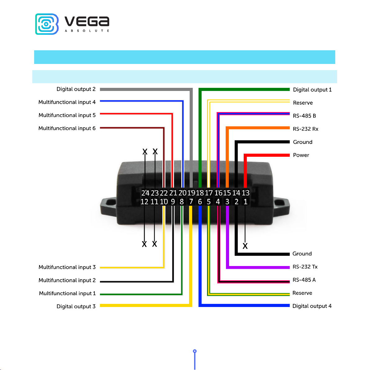
In the settings of multifunctional inputs in the “Configurator” application, in addition to
selecting a mode for each input, there is a parameter called “Active Level”. It can take the value
“low” and “high” and characterizes the magnitude and direction of the input tightening.
Input type
Low active level
High active level
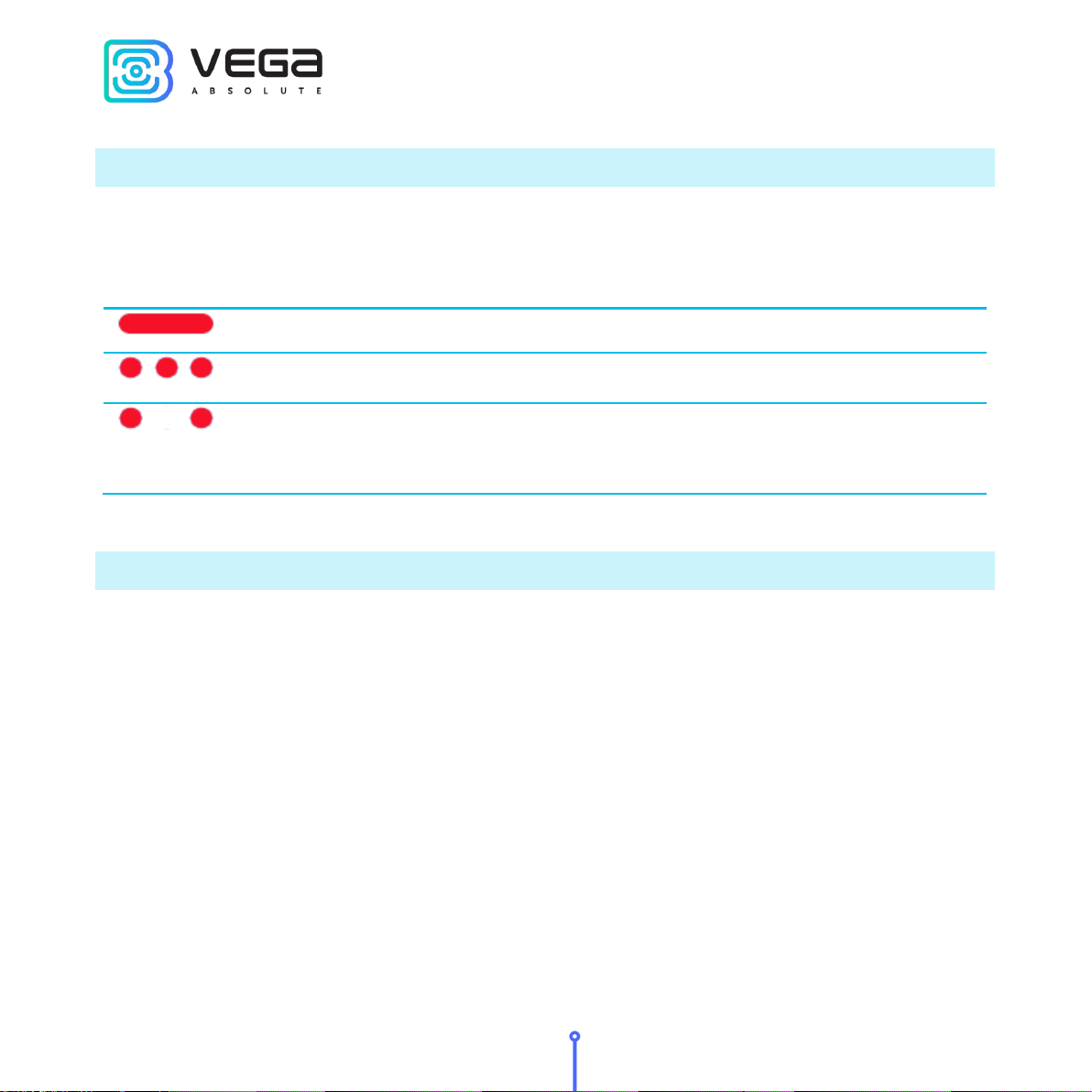
Analog Pull-down to the ground 22 kOhm Pull-down to the ground 22 kOhm
Digital Pull-up to external power 44 kOhm Pull-down to the ground 22 kOhm
Pulse
Pull-up to external power 44 kOhm
Pull-down to the ground 22 kOhm
Frequency Pull-up to external power 44 kOhm Pull-down to the ground 22 kOhm

Vega RP-1 / User Manual
11
Revision 02 - 03.12.2020
ACTUATORS
Actuators are connected to the device via digital outputs 1…4, which are of the type
“Open drain”.
Permissible load on each digital output 0.5 A
To increase the load on the outputs of the device, you must use an external relay. The
relay connection diagram is shown below.

Vega RP-1 / User Manual
12
Revision 02 - 03.12.2020
4 STORAGE AND TRANSPORTATION REQUIREMENTS
Port replicators shall be stored in the original packaging in heated room at temperatures
+5°С to +40°С and relative humidity less than 85%.
The device shall be transported in covered freight compartments of all types at any
distance at temperatures -40°C to +85°C. After transporting the devices at low temperatures, it is
recommended to hold them at room temperature for 24 hours before starting operation.

Vega RP-1 / User Manual
13
Revision 02 - 03.12.2020
5 CONTENT OF THE PACKAGE
The port replicator comes with the following items.
Port replicator Vega RP-1 – 1 pc.
Wire connector – 1 pc.
Factory certificate – 1 pc.

Vega RP-1 / User Manual
14
Revision 02 - 03.12.2020
6 WARRANTY
The warranty period for the port replicator is 36 months from the date of sale.
The manufacturer is obligated to provide repair services or replace the failed
device during 36 months from the date of sale.
The consumer is obliged to comply with the conditions and rules of
transportation, storage and operation specified in this user manual.
Warranty does not apply to:
- the device with mechanical, electrical and/or other damages and defects caused
by violation of the transportation, storage and operation requirements;
- incomplete devices;
- the device with traces of repair performed not by the manufacturer's service
center;
- the device with traces of oxidation or other signs of liquids leaking inside the
device.
In the event of a warranty claim, contact the service center:
113/1, Kirova Str., Novosibirsk, 630008, Russia.
Tel.: +7 (383) 206-41-35.

Vega RP-1 / User Manual
15
Revision 02 - 03.12.2020
vega-absolute.ru
User Manual © ООО Vega-Absolute, 2019-2020
This manual suits for next models
10
Table of contents