Vega VEGAMET 391 User manual

Operating Instructions
Signal conditioning and display
instrument for level sensors
VEGAMET 391
With SIL qualication
Document ID: 38704

2
Contents
VEGAMET 391 • With SIL qualication
38704-EN-170907
Contents
1 About this document ............................................................................................................... 4
1.1 Function ........................................................................................................................... 4
1.2 Target group ..................................................................................................................... 4
1.3 Symbols used................................................................................................................... 4
2 For your safety ......................................................................................................................... 5
2.1 Authorised personnel ....................................................................................................... 5
2.2 Appropriate use................................................................................................................ 5
2.3 Warning about incorrect use............................................................................................. 5
2.4 General safety instructions............................................................................................... 5
2.5 Safety label on the instrument .......................................................................................... 6
2.6 EU conformity................................................................................................................... 6
2.7 SIL conformity .................................................................................................................. 6
2.8 Installation and operation in the USA and Canada ........................................................... 6
2.9 Safety instructions for Ex areas ........................................................................................ 6
2.10 Environmental instructions ............................................................................................... 7
3 Product description ................................................................................................................. 8
3.1 Conguration.................................................................................................................... 8
3.2 Principle of operation........................................................................................................ 9
3.3 Adjustment ....................................................................................................................... 9
3.4 Packaging, transport and storage................................................................................... 10
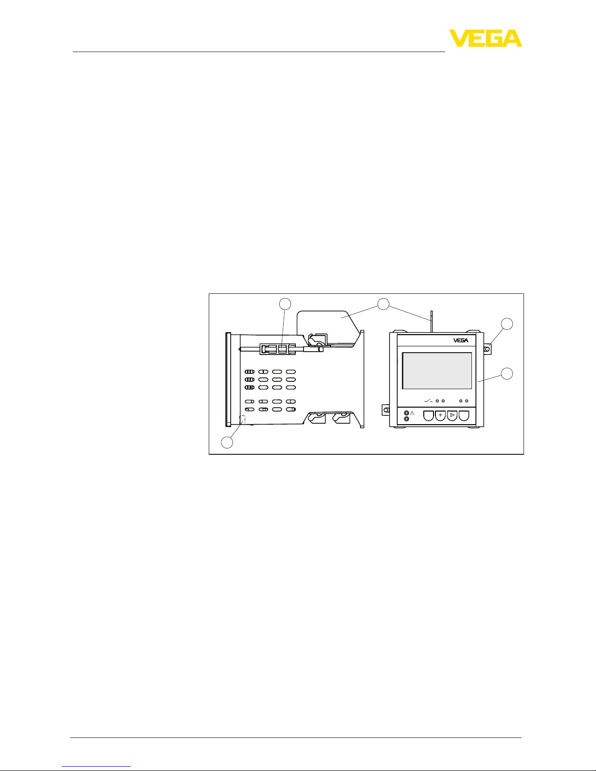
4 Mounting................................................................................................................................. 11
4.1 General instructions ....................................................................................................... 11
4.2 Mounting instructions ..................................................................................................... 11
5 Connecting to power supply................................................................................................. 14
5.1 Preparing the connection ............................................................................................... 14
5.2 Connection procedure.................................................................................................... 14
5.3 Wiring plan ..................................................................................................................... 16
6 Functional safety (SIL) .......................................................................................................... 17
6.1 Directive and scope........................................................................................................ 17
6.2 SIL qualication.............................................................................................................. 17
6.3 Application area ............................................................................................................. 17
6.4 Safety concept of the parameterization .......................................................................... 18
7 Setup with the integrated display and adjustment unit ..................................................... 20
7.1 Adjustment system......................................................................................................... 20
7.2 Setup steps .................................................................................................................... 21
7.3 Menu schematic............................................................................................................. 30
8 Setup with PACTware............................................................................................................. 36
8.1 Connect the PC.............................................................................................................. 36
8.2 Parameter adjustment with PACTware............................................................................ 36
9 Application examples ............................................................................................................ 38
9.1 Overll protection according to SIL................................................................................. 38
9.2 Dry run protection according to SIL2 .............................................................................. 39
9.3 Pump control 1/2 (run time controlled)............................................................................ 41
10 Maintenanceandfaultrectication...................................................................................... 44

3
Contents
VEGAMET 391 • With SIL qualication
38704-EN-170907
10.1 Maintenance .................................................................................................................. 44
10.2 Rectify faults................................................................................................................... 44
10.3 How to proceed if a repair is necessary.......................................................................... 46
11 Dismount................................................................................................................................. 47
11.1 Dismounting steps.......................................................................................................... 47
11.2 Disposal ......................................................................................................................... 47
12 Supplement ............................................................................................................................ 48
12.1 Technical data ................................................................................................................ 48
12.2 Dimensions .................................................................................................................... 51
12.3 Industrial property rights................................................................................................. 52
12.4 Trademark ...................................................................................................................... 52
Supplementary documentation
Information:
Supplementary documents appropriate to the ordered version come
with the delivery. You can nd them listed in chapter "Product descrip-
tion".
Editing status: 2017-09-04

4
1 About this document
VEGAMET 391 • With SIL qualication
38704-EN-170907
1 About this document
1.1 Function
This operating instructions manual provides all the information you
need for mounting, connection and setup of the instrument. Further-
more there are important instructions for maintenance, fault rectica-
tion, the exchange of parts and the safety of the user. Please read this
information before putting the instrument into operation and keep this
manual accessible in the immediate vicinity of the device.
1.2 Target group
This operating instructions manual is directed to trained specialist
personnel.The contents of this manual should be made available to
these personnel and put into practice by them.
1.3 Symbols used
Information, tip, note
This symbol indicates helpful additional information.
Caution: If this warning is ignored, faults or malfunctions can result.
Warning: If this warning is ignored, injury to persons and/or serious
damage to the instrument can result.
Danger: If this warning is ignored, serious injury to persons and/or
destruction of the instrument can result.
Ex applications
This symbol indicates special instructions for Ex applications.
SIL applications
This symbol indicates instructions for functional safety which must be
taken into account particularly for safety-relevant applications.
• List
The dot set in front indicates a list with no implied sequence.
→ Action
This arrow indicates a single action.
1 Sequence of actions
Numbers set in front indicate successive steps in a procedure.
Battery disposal
This symbol indicates special information about the disposal of bat-
teries and accumulators.

5
2 For your safety
VEGAMET 391 • With SIL qualication
38704-EN-170907
2 For your safety
2.1 Authorised personnel
All operations described in this operating instructions manual must
be carried out only by trained specialist personnel authorised by the
plant operator.
During work on and with the device the required personal protective
equipment must always be worn.
2.2 Appropriate use
VEGAMET 391 mit SIL-Qualikation is a universal signal condition-
ing instrument and power supply unit for connection of a 4 … 20 mA/
HART sensor.
You can nd detailed information about the area of application in
chapter "Product description".
Operational reliability is ensured only if the instrument is properly
used according to the specications in the operating instructions
manual as well as possible supplementary instructions.
For safety and warranty reasons, any invasive work on the device
beyond that described in the operating instructions manual may be
carried out only by personnel authorised by the manufacturer. Arbi-
trary conversions or modications are explicitly forbidden.
2.3 Warning about incorrect use
Inappropriate or incorrect use of the instrument can give rise to
application-specic hazards, e.g. vessel overll or damage to system
components through incorrect mounting or adjustment.Thus dam-
age to property, to persons or environmental contamination can be
caused. Also the protective characteristics of the instrument can be
inuenced.
2.4 General safety instructions
This is a state-of-the-art instrument complying with all prevailing
regulations and directives.The instrument must only be operated in a
technically awless and reliable condition. The operator is responsi-
ble for the trouble-free operation of the instrument. When measuring
aggressive or corrosive media that can cause a dangerous situation
if the instrument malfunctions, the operator has to implement suitable
measures to make sure the instrument is functioning properly.
During the entire duration of use, the user is obliged to determine the
compliance of the necessary occupational safety measures with the
current valid rules and regulations and also take note of new regula-
tions.
The safety instructions in this operating instructions manual, the na-
tional installation standards as well as the valid safety regulations and
accident prevention rules must be observed by the user.
For safety and warranty reasons, any invasive work on the device
beyond that described in the operating instructions manual may be

6
2 For your safety
VEGAMET 391 • With SIL qualication
38704-EN-170907
carried out only by personnel authorised by the manufacturer. Arbi-
trary conversions or modications are explicitly forbidden. For safety
reasons, only the accessory specied by the manufacturer must be
used.
To avoid any danger, the safety approval markings and safety tips on
the device must also be observed and their meaning looked up in this
operating instructions manual.
2.5 Safety label on the instrument
The safety approval markings and safety tips on the device must be
observed.
2.6 EU conformity
The device fulls the legal requirements of the applicable EU direc-
tives. By axing the CE marking, we conrm the conformity of the
instrument with these directives.
You can nd the EU conformity declaration on our website under
www.vega.com/downloads.
Electromagnetic compatibility
The instrument is designed for use in an industrial environment.
Nevertheless, electromagnetic interference from electrical conductors
and radiated emissions must be taken into account, as is usual with a
class A instrument according to EN 61326-1. If the instrument is used
in a dierent environment, its electromagnetic compatibility with other
devices must be ensured by suitable measures.
2.7 SIL conformity
This instrument fullls the requirements of functional safety according
to IEC 61508. You can nd further information in the supplied Safety
Manual.
2.8 Installation and operation in the USA and
Canada
This information is only valid for USA and Canada. Hence the follow-
ing text is only available in the English language.
Installations in the US shall comply with the relevant requirements of
the National Electrical Code (ANSI/NFPA 70).
Installations in Canada shall comply with the relevant requirements of
the Canadian Electrical Code
2.9 Safety instructions for Ex areas
Please note the Ex-specic safety information for installation and op-
eration in Ex areas. These safety instructions are part of the operating
instructions manual and come with the Ex-approved instruments.

7
2 For your safety
VEGAMET 391 • With SIL qualication
38704-EN-170907
2.10 Environmental instructions
Protection of the environment is one of our most important duties.
That is why we have introduced an environment management system
with the goal of continuously improving company environmental pro-
tection. The environment management system is certied according
to DIN EN ISO 14001.
Please help us full this obligation by observing the environmental
instructions in this manual:
• Chapter "Packaging, transport and storage"
• Chapter "Disposal"

8
3 Product description
VEGAMET 391 • With SIL qualication
38704-EN-170907
3 Product description
3.1 Conguration
The scope of delivery encompasses:
• VEGAMET 391 mit SIL-Qualikation signal conditioning instru-
ment
• Two clamping elements for panel mounting
• Ex separating wall
• Mini-USB cable
• Carrier rail adapter (optional)
• Documentation
– This operating instructions manual
– Ex-specic "Safety instructions"
– Safety Manual "Functional safety (SIL) according to IEC 61508"
– Documentation "SIL device settings"
– If necessary, further certicates
OK
ESC
SIL
on
VEGAMET 391
12 34
1
2
3
2
4
Fig. 1: VEGAMET 391 mit SIL-Qualikation
1 Ex separating wall
2 Clamping element for panel mounting
3 Display and adjustment unit
4 USB interface
The type label contains the most important data for identication and
use of the instrument:
• Instrument type
• Product code
• Approvals
• SIL identication
• Technical data
• ID numbers, instrument documentation
• Serial number of the instrument
• Order number
• Data matrix code for VEGA Tools app
The type label contains the serial number of the instrument. With it
you can nd the following data on our homepage:
• Product code of the instrument (HTML)
Scope of delivery
Constituent parts
T
ype label
Serial number

9
3 Product description
VEGAMET 391 • With SIL qualication
38704-EN-170907
• Delivery date (HTML)
• Order-specic instrument features (HTML)
• Operating instructions at the time of shipment (PDF)
• Safety instructions and certicates
Go to "www.vega.com", "Instrument search (serial number)". Enter
the serial number.
Alternatively, you can access the data via your smartphone:
• Download the "VEGA Tools" app from the "Apple App Store" or the
"Google Play Store"
• Scan the Data Matrix code on the type label of the instrument or
• Enter the serial number manually in the app
3.2 Principle of operation
VEGAMET 391 mit SIL-Qualikation is a universal signal conditioning
instrument for a variety of applications such as level, gauge and pro-
cess pressure measurement. At the same time, it can serve as power
supply unit for connected sensors. VEGAMET 391 mit SIL-Qualika-
tion is designed for connection of any 4 … 20 mA sensor.
Due to the SIL qualication, the instrument can be used in a safety-
relevant protective function. With single channel architectur, SIL2 is
reached, with multiple channel, diversitary architecture, SIL3. Take
note of the specications and requirements of the "Safety Manual".
The VEGAMET 391 mit SIL-Qualikation signal conditioning instru-
ment can power the connected sensor and process its measurement
signals.The requested parameter is shown on the display and also
outputted to the integrated current output for further processing. The
measurement signal can thus be transferred to a remote display or a
superordinate control system. Operating relays for control of pumps or
other devices are also integrated.
Wide range power supply unit with 20 … 253 V AC/DC for worldwide
use.
Detailed information about the power supply can be found in chapter
"Technical data".
3.3 Adjustment
The instrument can be adjusted with the following adjustment media:
• With integrated display and adjustment unit
• an adjustment software according to FDT/DTM standard, e.g.
PACTware and a Windows PC
The entered parameters are generally saved in VEGAMET 391 mit
SIL-Qualikation, when used with PACTware and PC also optionally
in the PC.
Information:
When using PACTware and the respective VEGA DTM, additional set-
tings can be carried out which are not possible or only partly possible
Application area
Functional principle
Voltage supply

10
3 Product description
VEGAMET 391 • With SIL qualication
38704-EN-170907
with the integrated display and adjustment unit. Communication is
carried out via the integrated USB interface.
3.4 Packaging, transport and storage
Your instrument was protected by packaging during transport. Its
capacity to handle normal loads during transport is assured by a test
based on ISO 4180.
The packaging of standard instruments consists of environment-
friendly, recyclable cardboard. For special versions, PE foam or PE
foil is also used. Dispose of the packaging material via specialised
recycling companies.
Transport must be carried out in due consideration of the notes on the
transport packaging. Nonobservance of these instructions can cause
damage to the device.
The delivery must be checked for completeness and possible transit
damage immediately at receipt. Ascertained transit damage or con-
cealed defects must be appropriately dealt with.
Up to the time of installation, the packages must be left closed and
stored according to the orientation and storage markings on the
outside.
Unless otherwise indicated, the packages must be stored only under
the following conditions:
• Not in the open
• Dry and dust free
• Not exposed to corrosive media
• Protected against solar radiation
• Avoiding mechanical shock and vibration
• Storage and transport temperature see chapter "Supplement -
Technical data - Ambient conditions"
• Relative humidity 20 … 85 %
With an instrument weight of more than 18 kg (39.68 lbs) suitable and
approved equipment must be used for lifting and carrying.
Packaging
Transport
Transport inspection
Storage
Storage and transport
temperature
Lifting and carrying

11
4 Mounting
VEGAMET 391 • With SIL qualication
38704-EN-170907
4 Mounting
4.1 General instructions
The instrument is designed for recessed installation in an instrument
panel, housing front plate or switching cabinet door. The required
cut-out is 92 x 92 mm (3.63 x 3.63 in) according to EN 60529. When
installed correctly, protection rating IP 65 is guaranteed. As an alter-
native, the instrument can be mounted in a switching cabinet or pro-
tective housing by means of four screws (attached with screws to rear
of housing). A mounting adapter for carrier rail mounting is available
as an option (top hat rail 35 x 7.5 according to DIN EN 50022/60715).
Note:
If the instrument is mounted via screws or carrier rail, it must always
be inside a switching cabinet or protective case.
A VEGAMET 391 mit SIL-Qualikation in Ex version is an auxiliary,
intrinsically safe instrument and may not be installed in explosion-
endangered areas.
Before setup, the Ex separating wall must be attached to Ex versions.
Safe operation can only be ensured if the operating instructions
manual and the EC type approval certicate are observed. VEGAMET
391 mit SIL-Qualikation must not be opened.
The instrument is suitable for standard ambient conditions acc. to
DIN/EN/IEC/ANSI/ISA/UL/CSA 61010-1.
Make sure that the degree of contamination specied in chapter
"Technical data" meets the existing ambient conditions.
4.2 Mounting instructions
1. Make sure that the cut-out required for mounting has a size of
92 x 92 mm (3.63 x 3.63 in).
2. Check for the correct position of the seal directly behind the front
plate and insert the instrument from the front into the front panel
cut-out.
3. Press the two tensioning elements into the provided gaps.
4. Screw in the two screws of the tensioning elements evenly with a
screwdriver.
Installation possibilities
Ambient conditions
Front panel mounting

12
4 Mounting
VEGAMET 391 • With SIL qualication
38704-EN-170907
3
2
1
Fig. 2: Front panel mounting
1 Front panel, front plate or switching cabinet door
2 Clamping elements
3 Slotted screw
→ Fasten the instrument by means of four screws (max. ø 4 mm) to
the inner side of the housing or to the mounting plate according to
the following illustration.
73 mm
(2.87")
86,5 mm
(3.41")
1
2
Fig. 3: Screw mounting
1 Fixing screw
2 Rear of the housing or mounting plate
1. Fasten the mounting plate to the instrument with the four en-
closed hexagon socket screws.
2. Screw the carrier rail adapter to the mounting plate with the four
enclosed Phillips-head screws.
Screw mounting
Carrier rail mounting

13
4 Mounting
VEGAMET 391 • With SIL qualication
38704-EN-170907
12 3 4
Fig. 4: Carrier rail mounting
1 Hexagon socket screws
2 Mounting plate
3 Carrier rail adapter
4 Phillips head screws

14
5 Connecting to power supply
VEGAMET 391 • With SIL qualication
38704-EN-170907
5 Connecting to power supply
5.1 Preparing the connection
Always keep in mind the following safety instructions:
Warning:
Connect only in the complete absence of line voltage.
• Connect only in the complete absence of line voltage
• If overvoltage surges are expected, overvoltage arresters should
be installed
Note:
Install a separating facility for the instrument which is easy to access.
The separating facility must be marked for the instrument (IEC/
EN 61010).
In hazardous areas you must take note of the respective regulations,
conformity and type approval certicates of the sensors and power
supply units.
The voltage supply can be 20 … 253 V AC/DC, 50/60 Hz.
The voltage supply of VEGAMET 391 mit SIL-Qualikation is con-
nected with standard cable according to the national installation
standards.
To connect the sensors, standard two-wire cable can be used. If elec-
tromagnetic interference is expected which is above the test values of
EN 61326 for industrial areas, screened cable should be used.
Make sure that the cable used has the required temperature resist-
ance and re safety for max. occurring ambient temperature
5.2 Connection procedure
Move on to electrical connection and proceed as follows:
1. Mount the instrument as described in the previous chapter
2. Remove terminal strip 1 on the upper side of the instrument
3. Connect sensor cable to terminal 1/2 (active input)
4. If necessary, connect digital inputs to 8/9 and 12
5. Plug terminal strip 1 to the upper side of the instrument
6. Remove terminal strip 2 on the lower side of the instrument
7. Connect power supply (switched o) to terminal 13/14
8. Connect current output (if not needed, it should be short-circuit-
ed)
9. If necessary, connect relays or other outputs
10. Plug in terminal strip 2 on the lower side of the instrument
11. For connection of additional relais to terminal strip 3, you have to
proceed as described earlier
The electrical connection is nished.
Safety instructions
Safety instructions
for Ex applications
Voltage supply
Connection cable

15
5 Connecting to power supply
VEGAMET 391 • With SIL qualication
38704-EN-170907
Note:
If the current output is not needed, the terminals must be short-
circuited, because the output is monitored and a failure message is
outputted when being interrupted.
Remember that with Ex applications, the Ex separating wall must be
plugged onto the upper side of the instrument before setup.
Information:
On the active input (terminal 1/2), VEGAMET 391 mit SIL-Qualika-
tion provides power for the connected sensors. Power supply and
measurement data are transmitted over the same two-wire cable.This
mode is provided for connection of measuring transducers without
separate voltage supply (sensors in two-wire version).
A passive input is not available with VEGAMET 391 with SIL qualica-
tion.

16
5 Connecting to power supply
VEGAMET 391 • With SIL qualication
38704-EN-170907
5.3 Wiring plan
8711103954216 12
1718 141522 1620212324 19 13
2930 262734 2832333536 31 25
+- L+
N-
+++--
4 3
7 8 9
1 5 62
10
11
OK
ESC
on
12
SIL
34
Fig. 5: Wiring plan with two-wire sensor
1 Relay 1
2 Relay 2 (optional fail safe relay)
3 Relay 3 (SIL)
4 Relay 4 (SIL)
5 Current output
6 Voltage supply of the signal conditioning instrument
7 Measurement data input with sensor supply (active input)
8 Connection for HART modem for sensor parameter adjustment
9 Digital input 1 and 2
10 Common ground for digital input 1/2
11 4 … 20 mA/HART sensor (two-wire version)
Wiring plan for two-wire
sensor

17
6 Functional safety (SIL)
VEGAMET 391 • With SIL qualication
38704-EN-170907
6 Functional safety (SIL)
6.1 Directive and scope
In case of dangerous failures, processing facilities and machines can
cause risks for persons, environment and property. The risk of such
failures must be judged by the plant operator. Dependent thereon are
measures for risk reduction through error prevention, error detection
and fault control.
The part of plant safety depending on the correct functioning of
safety-related components for risk reduction is called functional
safety. Components used in such safety-instrumented systems (SIS)
must therefore execute their intended function (safety function) with a
dened high probability.
The safety requirements for such components are described in
the international standard IEC 61508, which sets the measure for
unique and comparable judgement of instrument safety and hence
contributes to worldwide legal certainty. Depending on the degree
of required risk reduction, we distinguish between four safety levels,
from SIL1 for low risk to SIL4 for very high risk (SIL = Safety Integrity
Level).
6.2 SILqualication
In the development of instruments used in safety-instrumented sys-
tems, avoiding systematic errors as well as determining and correct-
ing random errors is given great importance.The operator also gets
information that helps him full the requirements on the functional
safety of his system.
Here the most important characteristics and requirements from the
perspective of functional safety according to IEC 61508:
• Internal monitoring of safety-relevant circuit parts
• Extended standardization of the software development
• In case of failure, switching of the safety-relevant outputs to a
dened safe state
• Determination of the failure probability of the dened safety func-
tion
• Reliable parameterization with non-safe user environment
• Recurring function test
The SIL qualication of components is specied in a manual on func-
tional safety (Safety Manual). Here, you can nd all safety-relevant
characteristics and information the user and the planner need for
planning and operating the safety-instrumented system.This docu-
ment is attached to each instrument with SIL rating and can be also
found on our homepage via the instrument search.
6.3 Application area
The signal conditioning instrument is used in combination with a SIL
qualied 4 … 20 mA sensor if safety-relevant protective functions are
required.
Additional characteristics
and requirements

18
6 Functional safety (SIL)
VEGAMET 391 • With SIL qualication
38704-EN-170907
The following inputs/outputs are permitted:
• 4 … 20 mA sensor input with transmitter power supply
• Relay outputs 3/4
• 4 … 20 mA current output
Note:
The following inputs/outputs are not permitted for safety-relevant
applications:
• Digital input 1/2
• Relay output 1/2
• Measured value transmission via the communication interfaces
(USB/HART)
6.4 Safety concept of the parameterization
The following tools are permitted for parameterization of the safety
function:
• The integrated display and adjustment unit for on-site adjustment
• The DTM suitable for the signal conditioning instrument in con-
junction with an adjustment software according to the FDT/DTM
standard, e. g. PACTware
Note:
For operation of the VEGAMET 391 mit SIL-Qualikation the DTM
Collection 06/2011 or higher is required. The modication of safety-
relevant parameters is only possible with active connection to the
instrument (online mode).
To avoid possible errors during parameterization in a non-safe user
environment, a verication procedure is used that makes it possible
to detect parameterization errors reliably. For this, safety-relevant
parameters must be veried before they are stored in the device. In
normal operating condition, the instrument is also locked against
parameter changes through unauthorized access.This concept ap-
plies to the adjustment on the instrument but also to adjustment with
PACTware with DTM.
All safety-relevant parameters must be veried after a change and
conrmed by a character string comparison. The following parameters
of the relays 3/4 are judged as safety-relevant:
• Mode relay output
• Relay switching point Hi
• Relay switching point Lo
The parameter settings of the measurement loop must be document-
ed. For this purpose, the document "SIL device settings" is attached
to each instrument already listing all safety-relevant parameters in
the shipping status as well as containing free space for own notes.
This document is also available via the instrument search on our
homepage. In addition, a list of the safety-relevant parameters can be
stored and printed via PACTware/DTM.
Tool for operation and
parameterization
Safe parameterization
Safety-relevant param-
eters

19
6 Functional safety (SIL)
VEGAMET 391 • With SIL qualication
38704-EN-170907
For each parameter change, the instrument must be unlocked via
a PIN (see chapter "Setup steps - Unlock adjustment"). The device
status is indicated via the symbol of an unlocked or locked padlock.
Warning:
If the instrument is unlocked, the safety function must be classied as
unsafe. This applies until the parameterization is terminated correctly.
If necessary, other measures must be taken to maintain the safety
function.
All parameters changed by the operator are marked automatically so
that they can veried in the next step.
For the verication the PIN must be entered rst and a comparison of
two character strings must be carried out. The user must conrm that
both character strings are identical, this is used to check the charac-
ter representation and the communication channels. The verication
texts are provided in German and with all other menu languages in
English.
In a second step, all the modied, safety-relevant parameters that are
listed must be conrmed. After this process is nished, the adjust-
ment mode will be locked automatically and the safety function is
guaranteed again.
Warning:
If the described process was not carried out completely or correctly
(e.g. interruption or voltage loss), the instrument remains in unsafe
and unlocked status.
Warning:
In case of a reset to basic settings, all safety-relevant parameters will
also be reset to default. Therefore all safety-relevant parameters must
be checked or readjusted.
Unlock instrument
Unsafe device
status
Change parameters
Verify parameter/Unlock
instrument
Incomplete process
Instrument reset

20
7 Setup with the integrated display and adjustment unit
VEGAMET 391 • With SIL qualication
38704-EN-170907
7 Setup with the integrated display and
adjustment unit
7.1 Adjustment system
The integrated display and adjustment unit is used for measured
value display, adjustment and diagnosis of VEGAMET 391 mit SIL-
Qualikation. The indication and adjustment are carried out via four
keys and a clear, graphic-capable display with background lighting.
The adjustment menu with selectable language is clearly structured
and enables easy setup.
Certain adjustment options are not available or only partially available
with the integrated display and adjustment unit, e.g. the settings for
ow measurement. For such applications, the use of PACTware with
appropriate DTMs is recommended.
OK
ESC
on
VEGAMET 391
12
SIL
34
4
5
3
2
1
Fig. 6: Display and adjustment elements
1 LC display
2 Adjustment keys
3 Status indication operation
4 Status indication fault signal
5 Status indication operating relay 1 … 4
• [OK] key:
– Move to the menu overview
– Conrm selected menu
– Edit parameter
– Save value
• [->] key to select:
– Menu change
– Select list entry
– Select editing position
• [+] key:
– Change value of the parameter
• [ESC] key:
– Interrupt input
Function
Display and adjustment
elements
Key functions
Other manuals for VEGAMET 391
2
Table of contents
Other Vega Monitor manuals