Veichi Electric VC-4AD User manual

1
VC-4AD Analog Input Module User's Manual
Thank you for purchasing the VC-4AD analog input module developed and manufactured by Suzhou VEICHI Electric
Technology Co. Before using our VC series PLC products, please read this manual carefully, so that you can grasp the
characteristics of the product more clearly and install and use it correctly. You can make full use of the rich functions of this
product for safer application.
Tip:
Before starting to use, please read the operation instructions, precautions carefully to reduce the occurrence of accidents.
Personnel responsible for the installation and operation of the product must be strictly trained to comply with the safety codes of
the relevant industry, strictly observe the relevant equipment precautions and special safety instructions provided in this manual,
and perform all operations of the equipment in accordance with the correct operating methods
1 Interface Description
1.1 Interface Description
The VC-4AD has a cover for both the expansion interface and the user terminal, and the appearance is shown in Figure 1-1.
RUN
ERR VC-4AD
VEICHI
24VV1+ I1+
VI1-
PG
COM
Sliding clips
DIN slot clips
Product
Tags
Extended
male plug
Exte ns ion female socke t
Status Indicator
Wiring terminals
Terminal cover
1
2
3
4
5
6
7
8
9
10
11
12
13
14
15
16
17
18
V2+ I2+
VI2-V3+ I3+
VI3-V4+ I4+
VI4-
Figure 1-1 Appearance of the module interface
1.2 Model description
VC- 4 AD
AD (Analog Inp ut Module)
Number of analog channels (4-channel
input in the example)
VC:VEICHI Programmable controller
Figure 1-2 Illustrative diagram of the product model

2
1.3 Definition of terminals
No
Marking
Instructions
No
Marking
Instructions
01
24V
Analogue power supply 24V positive
02
COM
Analogue power supply 24V negative
03
V1+
Voltage signal input for channel 1
04
PG
Grounded terminal
05
I1+
Channel 1 current signal input
06
VI1–
Channel 1 common ground end
07
V2+
Channel 2 voltage signal input
08
Reserved
09
I2+
2nd channel current signal input
10
VI2-
Channel 2 common ground end
11
V3+
Voltage signal input for channel 3
12
Reserved
13
I3+
Channel 3 current signal input
14
VI3–
Channel 3 common ground end
15
V4+
Channel 4 voltage signal input
16
Reserved
17
I4+
Channel 4 current signal input
18
VI4–
Channel 4 common ground end
1-3 Terminal definition table
Note: For each channel, voltage and current signals cannot be input at the same time. When measuring current signals, please
short the channel voltage signal input to the current signal input.
1.4 Access systems
The expansion interface allows the VC-4AD to be connected to a main module of the VC series PLC or to other expansion
modules. The expansion interface can also be used to connect other expansion modules of the same or different models of the VC
series. This is shown in Figure 1-4.
Push right Push left
VC1-1614MAR
Figure 1-4 Schematic diagram of the connection to the main module and other expansion modules

3
1.5 Wiring instructions
User terminal wiring requirements, as shown in Figure 1-5.
Figure 1-5 Diagram of user terminal wiring
The diagrams ①to ⑦indicate the seven aspects that must be taken into account when wiring.
1. It is recommended that the analogue input is connected via a twisted shielded cable. The cable should be routed away
from power cables or other wires that may cause electrical interference.
2. If there are fluctuations in the input signal, or if there is electrical interference in the external wiring, it is recommended to
connect a smoothing capacitor (0.1μF to 0.47μF/25V).
3. If the current channel uses the current input, short the voltage input and the current input for that channel.
4. If there is excessive electrical interference, connect the shielding ground FG to the module earth terminal PG.
5. Ground the module's earth terminal PG well.
6. The analogue power supply can use the 24 Vdc power supply from the main module output, or any other power supply
that meets the requirements.
7. Do not use the empty pins on the user terminals.
2 Instructions for use
2.1 Power indicators
Table 2-1 Power supply indicators
Projects
Description
Analog circuits
24Vdc (-10% to +10%), maximum allowable ripple voltage 2%, 50mA (from mains module or external power supply)
Digital Circuits
5Vdc, 70mA (from the main module)
⑦
⑤
CH1
⑥
DC/DC
Converter
+5V
AGND
-5V
PGND
VC-4AD
24
V
dc
±
1
0
%
60
mA
FG
AGND
④
AGND
Current signals
CH4
AGND
250
390K
AGND
Voltage signals
①
②
②
③
①
390K
130K
130K
24V-
24V+
130K
130K
390K
390K
250
V4+
I4+
VI4-
FG
V1+
I1+
VI1-

4
2.2 Performance indicators
Table 2-2 Performance indicators
Projects
Indicators
Conversion speed
2ms/channel
Analogue
input range
Voltage input
-10Vdc to +10Vdc, input impedance
1MΩ
4 channels can be used simultaneously.
Current input
-20mA to +20mA, input impedance 250Ω
Digital output
Current setting range: -2000 to +2000
Voltage setting range: -10000 to +10000
Ultimate voltage
±12V
Ultimate current
±24mA
Resolution
Voltage input
1mV
Current input
10μA
Precision
±0.5% of full scale
Isolation
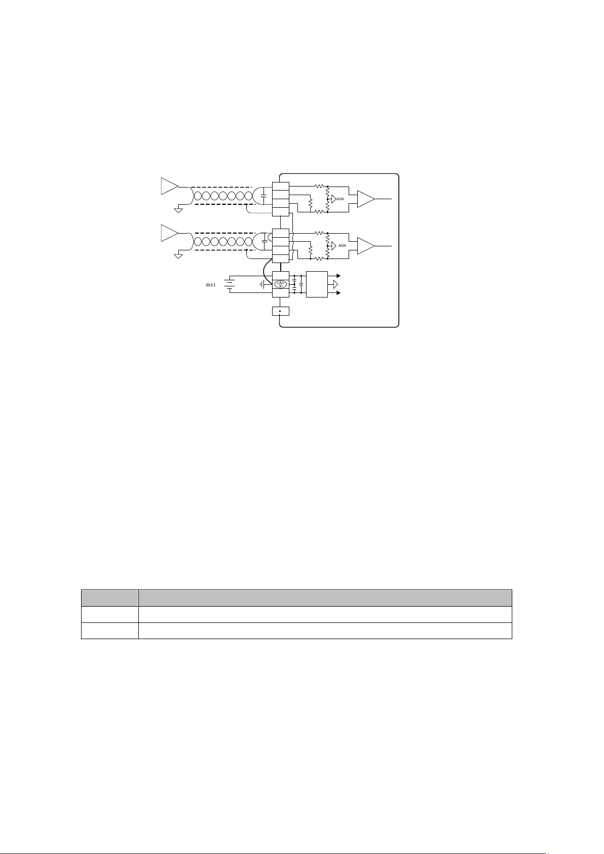
The analogue circuitry is isolated from the digital circuitry by an opto-coupler. The analogue
circuitry is internally isolated from the module input 24Vdc supply. No isolation between
analogue channels
2.3 Indicator light description
Projects
Description
Signal indicator
RUN status indicator, blinking when normal
ERR error status indicator, illuminated on failure
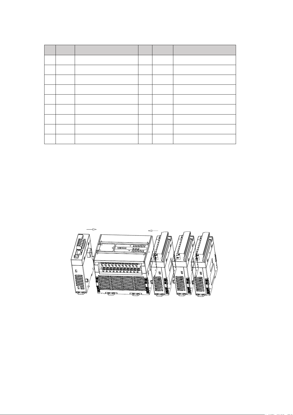
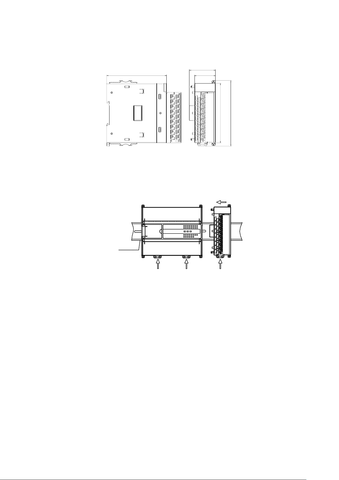
Expansion module rear stage interface
Connection of rear modules, hot-swappable not supported
Expansion module front interface
Connection of front-end modules, hot-swappable not supported
3 Characteristic settings
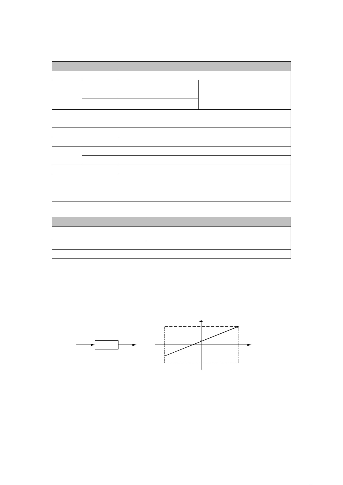
The input channel characteristics of the VC-4AD are the linear relationship between the channel analogue input quantity A
and the channel digital output quantity D, which can be set by the user. Each channel can be understood as the model shown in
Figure 3-1, and since it is a linear characteristic, the characteristics of the channel can be determined by determining two points P0
(A0, D0) and P1 (A1, D1), where D0 indicates that when the analogue input isA0 D0 indicates the channel output digital quantity
when the analogue input isA0 and D1 indicates the channel output digital quantity when the analogue input is A1.
D1
A
Channel Characteristics
D0
A0 A1
P 1
P0
D
Channel D
Digital Output
A
Analog input Channel model
Figure 3-1 Schematic diagram of the channel characteristics of the VC-4AD
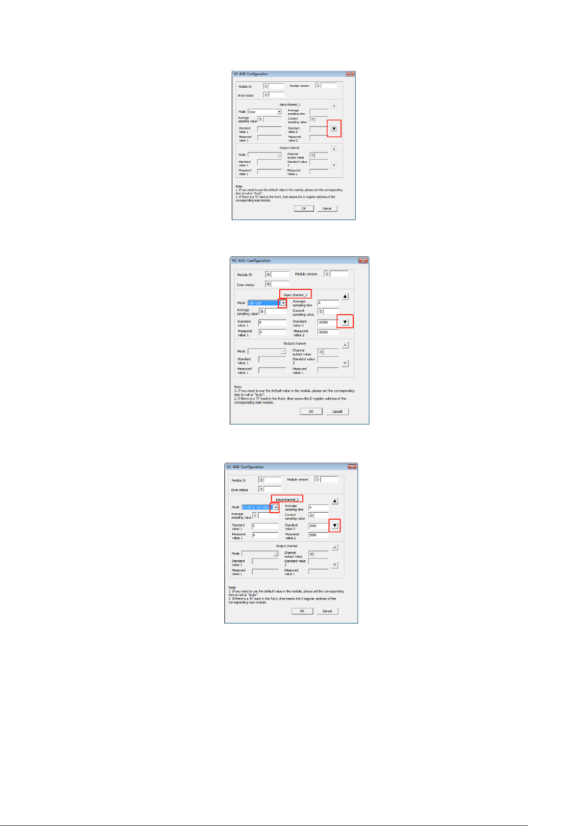
In consideration of the user's ease of use and without affecting the realization of the function, in the current mode, A0 and
A1 correspond to [Actual Value 1] and [Actual Value 2] respectively, and D0 and D1 correspond to [Standard Value 1] and
[Standard Value 2] respectively, as shown in Figure 3-1, the user can change the channel characteristics by adjusting (A0,D0) and
(A1,D1), the factory default (A0,D0) is the external The factory default (A0,D0) is the 0 value of the external analogue input,
(A1,D1) is the maximum value of the external analogue input. This is shown in Figure 3-2.

5
010000
10000
-10000
-10000
A(mV)
D
A.Mode 0 (factory setting)
Figure 3-2 Channel characteristic change for VC-4AD
If you change the value of D0 and D1 of the channel, you can change the channel characteristics, D0 and D1 can be set
anywhere between -10000 and +10000, if the set value is out of this range, VC-4AD will not receive and keep the original valid
setting, Figure 3-3 shows the example of characteristics change, please refer to it.
A(mv)
0
- 10000
-10000
D
10000
10000
A.Mode 0 , D0=0,D1=10000
Input 10V, corresponding to digital 10000
Input 0V, corresponding to digital quantity 0
Input -10V, corresponding to digital quantity -10000
Figure 3-3 Example of a feature change
4 Programming examples
4.1 Programming example for VC series + VC-4AD module
Example: VC-4AD module address is 1, use its 1st channel input voltage signal (-10V to +10V), 2nd channel input current signal
(-20mA to +20mA), close the 3rd channel, set the average number of points to 8, and use data registers D0 and D2 to receive the
average conversion result.
1)Create a new project and configure the hardware for the project, as shown below
Figure 4-1 Hardware configuration
2)Double click on the "VC-4AD" module on the rail to enter the 4AD configuration parameters.
Select the VC-4AD and drag it onto
the rail

6
4-2 Basic application channel one setup
3)Click on "▼" to configure the second channel mode
4-3 BasicApplication Channel 2 Setup
4)Click on "▼" to configure the third channel mode and click on "Confirm" when finished.
4-4 Basic application channel three setup

7
5 Installation
5.1 Size specification
91.7 32
90
99.2
40
RUN
ERR
VC-4AD
VEICHI
24+ V1+ I1+ V2+ I2+ V3+ I3+ V4+ I4+
VI4-
VI3-
VI2-
VI1-
PG
COM
Figure 5-1 External dimensions and mounting hole dimensions (unit: mm)
5.2 Installation method
The installation method is the same as that for the main module, please refer to the VC Series Programmable Controllers
User Manual for details.An illustration of the installation is shown in Figure 5-2
.
35mm wide DIN slot
Press back the DIN slot snap
IN
0UT
PWR RUN ERR
00 01 02 03 04 05 06 07
10 11 12 13 14 15 16 17
00 01 02 03 04 05 06 07
10 11 12 13 14 15
VC1-1614MAR
VEICHI
RU N
ER R
VC-4AD
VEICHI
24+ V1+ I1+
PG
COM VI1-
V2+ I2+
VI2-
V3+ I3+
VI3-
V4+ I4+
VI4-
Figure 5-2 Fixing with DIN slot
6 Operational checks
6.1 Routine checks
1. Check that the analogue input wiring meets the requirements (see 1.5 Wiring instructions).
2. Check that the VC-4AD expansion connector is reliably plugged into the expansion connector.
3. Check that the 5V and 24V power supplies are not overloaded. Note: The power supply for the digital part of the VC-4AD
comes from the main module and is supplied via the expansion interface.
4. Check the application to ensure that the correct operating method and parameter range has been selected for the application.
5. Set the VC main module to RUN.
6.2 Fault checking
If the VC-4AD is not running properly, check the following items.
●Checking the status of the main module "ERR" indicator.
blinking: check whether the expansion module is connected and whether the configuration model of the special module is the
same as the actual connected module model.
extinguished: the extension interface is correctly connected.
●Check the analogue wiring.
Confirm that the wiring is accurate and can be wired as shown in Figure 1-5.●Check the status of the module's "ERR" indicator
Lit: 24Vdc power supply may be faulty; if 24Vdc power supply is normal, the VC-4AD is faulty.

8
Off: 24Vdc power supply is normal.
●Check the status of the "RUN" indicator
blinking: the VC-4AD is operating normally.
Information for users
1. The scope of the warranty refers to the programmable controller body.
2. The warranty period is eighteen months. If the product fails or is damaged during the warranty period under normal use, we
will repair it free of charge.
3. The start of the warranty period is the date of manufacture of the product, the machine code is the only basis for determining
the warranty period, equipment without the machine code is treated as out of warranty.
4. Even within the warranty period, a repair fee will be charged for the following cases.
failure of the machine due to non-operation in accordance with the user manual.
Damage to the machine caused by fire, flooding, abnormal voltage, etc..
Damage caused when using the programmable controller for a function other than its normal function.
5. The service charge will be calculated on the basis of the actual cost, and if there is another contract, the contract will take
precedence.
6.Please make sure that you keep this card and present it to the service unit at the time of warranty.
7. If you have questions, you can contact the agent or contact us directly.
Suzhou VEICHI Electric Technology Co.ltd
China Customer Service Centre
Address: No.1000 Song Jia Road, Wuzhong Economic & Technological Development Zone
Tel: 0512-66171988 Fax: 0512-6617-3610
Service Hotline: 400-600-0303 Website: www.veichi.com
Data Version V1.0 Archived 2021-07-30
All rights reserved. Contents are subject to change without prior notice.
VEICHI Product Warranty Card
Customer
Information
Unit address.
Name of unit.
Contact person.
Contact number.
Product
information
Product type.
Fuselage barcode.
Name of agent.
Fault
information
Repair time and content:.
Maintenance people:
Mailing
Address
Suzhou VEICHI Electric Technology Co.
Address: No. 1000, Songjia Road, Wuzhong Economic and
Technological Development Zone
Table of contents
Other Veichi Electric Control Unit manuals
Popular Control Unit manuals by other brands

Vimar
Vimar ELVOX RS14 Installation and operation manual

Yamatake
Yamatake ACTIVAL VY51X2J Specifications & instructions

Emerson
Emerson KTM Series Installation and maintenance manual

Telit Wireless Solutions
Telit Wireless Solutions LE910Cx Hardware user's guide

Leadshine
Leadshine CS-D1008 user manual

General DataComm
General DataComm TMS-3000 Operating and installation instructions

Beijer Electronics
Beijer Electronics VICPAS EXTER T70 installation manual

Kathrein
Kathrein HDS 66 quick start guide

Danfoss
Danfoss CVP installation guide

HMS
HMS Anybus Communicator user manual

Trotec
Trotec HG 135 Original instructions

Force
Force CNC BTN Series Installation, operation and maintenance manual