ECM-RS2D | RS232/RS485/DMX512 Ports Module | revision 2.30
©HighCross Ltd.
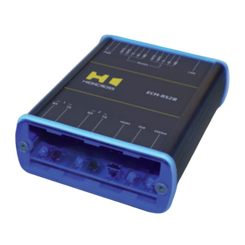
LED “status” indicates the power connection
and connection status with controllers
Off No power connected
Blink
(1 Hz) No connection with external controllers
Fast blink
(4 Hz) The device is in bootloader mode
On Connected to external controllers
LED “link“ indicates Ethernet network
link and activity
Off No connection to Ethernet network
Blink Connected to Ethernet network
Receiving Ethernet data packets
On Connected to Ethernet network
No network activity
LEDs “TX1”, ”TX2”, ”RX1”, ”RX2“ display activity
of serial ports
Off The port’s activity is absent
On Data is sending/receiving via the port
LEDs “RS485 – 1” and ”RS485 – 2“ display activity
of serial ports
Off The port is in RS232 mode
On Indicates RS485 or DMX512 mode
Multifunctional button “reset“
To reboot the device push the button for 1 second
To reset the device to factory defaults push and hold the
button for 5 seconds.
IP–address will be set to 10.0.1.101, subnet mask - to
255.255.255.0. All other settings will be set to default values
For rmware update, power off the device, push and hold
the button and power the device on. Release the button after
the LED “status” will start to blink fast.
The network settings of the device started in bootloader
mode are: IP–address – 10.0.1.101, subnet mask –
255.255.255.0
The PWR “+” and “–” terminals are designed to power the device
12–24 VDC if connected Ethernet switch has no PoE support.
Terminals GND, RX, TX, RTS and CTS of ports 1–2 are designed to
connect signals of RS232 interface.
Terminals A(–) and B(+) of ports 1–2 are designed to connect
signals of RS485 and DMX512 interface.
Be sure that the port set to needed RS232 or RS485 mode before
connecting the terminals to avoid equipment damage. The LEDs
“RS485 – 1” and ”RS485 – 2“ are designed to quick visual check of
RS485 mode when the device is powered.
SETUP AND CONFIGURATION
The conguration of the module is handled via web-interface.
To start working with the device:
• Connect the device to the Ethernet switch. If the switch has
no PoE support, connect the power 12–24 VDC to the PWR
terminal
• Ensure that your computer can connect to the network address
10.0.1.101 or set the TCP/IP settings of active network adap-
tor to: IP address –
10.0.1.100
, subnet mask –
255.255.255.0
• Enter 10.0.1.101 in address bar of your web-browser
• Enter: login – root, password – root
• Congure the device settings
The web-interface contains the next web-pages:
Home Displays the hardware revision and the
rmware version
Settings Network settings, type of data exchange
protocol
Ports
conguration
Settings for serial ports – physical interface
type, baud rate, data bits, parity, stop bits,
CTS/RTS mode
Settings for DMX512 mode – Break, MAB and
Idle parameters
Status Displays current TCP/IP connections and device
uptime info
For further information refer to www.highcross.pro
