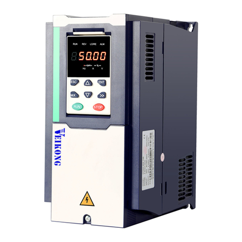
Veikong VFD530 User manual

Operation user manual
VFD530 AC drive
High Performance vector and torque

Preface
Thank you for purchasing the VFD530 series high performance vector and torque control frequency
inverter. VFD530 series drivers can drive both induction motors and permanent magnet synchronous
motors. VFD530 series with advanced functions, such as high performance vector control of induction
motor, user-programmable function and backstage monitoring software, variable communication and
supporting multiple PG cards etc. It is applicable to textile, papermaking, tension control, wire drawing
fans and pumps, machine tools, packaging, food and all kinds of automatic production equipment.Its
excellent performance is equivalent and competitive to most of international brand AC drives
This manual introduces functional characteristics and usage of VFD530 series inverter, includes product
model selection, parameter settings, running and debugging, maintenance, checking, and so on. Please
be sure to read this manual carefully before operation. For equipment matching manufacturers, please
send this manual to your end user together with your devices, in order to facilitate the usage.
PRECAUTIONS
◆To describe the product details, the illustrations in the manual sometimes are under the state of
removing the outer housing or security covering. While using the product, please be sure to mount
the housing or covering as required, and operate in accordance with the contents of manual.
◆The illustrations in this manual is only for explanation, may be different from the products you
ordered.
◆Committed to constantly improving the products and features will continue to upgrade, the
information provided is subject to change without notice.
◆Please contact with the regional agent or client service center directly of factory if there is any
questions during usage.
EDIT: V1.0
TIME: 2021-02

Contents
Chapter 1 Safety Information and Precautions.......................................................................................... 1
1.1 Safety Precautions........................................................................................................................... 1
1.2 Precaution ......................................................................................................................................... 2
Chapter 2 Product Information ..................................................................................................................... 4
2.1 Designation Rules............................................................................................................................ 4
2.2 Product series instruction ............................................................................................................... 4
2.3 Technical Specifications.................................................................................................................. 6
Chapter 3 Product appearance and Installation Dimension .............................................................. 9
3.1 Product appearance and installation............................................................................................. 9
3.1.1 Product appearance............................................................................................................. 9
3.1.2 Appearance and Mounting Hole Dimension ................................................................... 12
3.1.3 Removal and installation of cover and inlet plate .......................................................... 17
3.2 Wiring............................................................................................................................................... 20
3.2.1 Standard wiring diagram.................................................................................................... 20
3.2.2 Main Circuit Terminals........................................................................................................ 21
3.2.3 Terminal screws and wiring specifications ...................................................................... 22
3.2.4 Cautions for Main Circuit Wiring....................................................................................... 24
3.2.5 Control Circuit Terminal ..................................................................................................... 25
3.3 EMCquestion and solution............................................................................................................ 31
Chapter 4 Operation and display ............................................................................................................... 33
4.1 LED Instruction of operation and display ................................................................................... 33
4.2 Display hierarchy and menu mode.............................................................................................. 34
4.3 Digital tube display......................................................................................................................... 35
4.4 Test run............................................................................................................................................ 36
Chapter 5 Function Code Table.................................................................................................................. 38
Chapter 6 Fault Diagnosis and Solution ................................................................................................. 122
6.1 Failure and diagnosis .................................................................................................................. 122
6.2 Warning type................................................................................................................................. 128
Chapter 7 Selection Guide of inverter Accessory.................................................................................. 130
7.1 Selection Guide of braking component..................................................................................... 130
7.2 PG card type................................................................................................................................. 131
7.3 IO Extension card ........................................................................................................................ 134
7.4 CANopen exentsion card............................................................................................................ 136
Chapter 8 Daily maintenance of frequency inverters............................................................................ 139
8.1 Daily maintenance ....................................................................................................................... 139
8.1.1 Daily maintenance ............................................................................................................ 139
8.1.2 Regular inspection............................................................................................................ 139
8.2 Wearing parts replacement ........................................................................................................ 139
8.3 Warranty Items ............................................................................................................................. 140
Appendix A Modbus communication protocol ..................................................................................... 141

VFD530 high performance vector control frequency inverter user manual Chapter 1 Safety information and precautions
- 1-
Chapter 1 Safety Information and Precautions
Safety Definitions: In this manual, safety precautions are divided into the following two categories:
indicates that failure to comply with the notice will result in serious injury or even death
indicates that failure to comply with the notice will result in moderate or minor injury and
equipment damage
Read this manual carefully so that you have a thorough understanding. Installation, commissioning or
maintenance may be performed in conjunction with this chapter. will assume no liability or responsibility
for any injury or loss caused by improper operation.
1.1 Safety Precautions
Use stage
Security Level
Precautions
Before
Installation
DANGER
➢packing water, parts missing or damaged parts, please do not install!
➢Packaging logo and physical name does not match, please do not
install!
WARNING
➢Handling should be light lift, otherwise there is the danger of damage
to equipment!
➢Do not use damaged drive or missing drive. Risk of injury!
➢Do not touch the control system components by hand, or there is the
danger of electrostatic damage!
During
Installation
DANGER
➢Please install the flame retardant objects such as metal, away from
combustibles, or may cause a fire!
WARNING
➢Do not allow lead wires or screws to fall into the drive, otherwise the
drive may be damaged!
➢Install the drive in a place where there is less vibration and direct
sunlight.
➢Drive placed in airtight cabinet or confined space, please note the
installation of space to ensure the cooling effect.
Wiring
DANGER
➢You must follow the guidance of this manual and be used by qualified
electrical engineers. Otherwise, unexpected danger may occur!
➢There must be a circuit breaker between the drive and the power
supply, otherwise a fire may occur!
➢Make sure the power supply is in zero-energy state before wiring,
otherwise there is danger of electric shock!
➢Please follow the standard to the drive properly grounded, otherwise
there is the risk of electric shock!
WARNING
➢Never connect input power to the drive's output terminals (U, V, W).
Note that the terminal markings, do not take the wrong line! Otherwise
it will cause damage to the drive!
➢Never connect the braking resistor directly to the DC bus +, -
terminals. Otherwise it will cause a fire!
➢Refer to the manual's recommendations for the wire diameter used.
Otherwise it may happen accident!
➢Do not disassemble the connecting cable inside the driver. Otherwise,
the internal of the servo driver may be damaged.
Before
Power-on
DANGER
➢Make sure the voltage level of the input power is the same as the
rated voltage of the driver. Check if the wiring position of the power
input terminals (R, S, T) and output terminals (U, V, W) is correct; Of

Chapter1 Safety information and precaution VFD530 high performance vector control frequency inverter user manual
- 2 -
Use stage
Security Level
Precautions
the external circuit is short-circuited, the connection is tightened, or
cause damage to the drive!
➢No part of the drive need to withstand voltage test, the product has been
made before the test. Otherwise it may cause accident!
WARNING
➢The driver must be covered before the cover can be powered,
otherwise it may cause electric shock!
➢All peripheral accessories must be wired according to the instructions
in this manual, and be properly wired in accordance with this manual.
Otherwise it may cause accident!
After Power-
on
DANGER
➢Do not open the cover after power on, otherwise there is danger of
electric shock!
➢If the indicator light does not light after power on, the keyboard does
not display the situation, immediately disconnect the power switch, do
not touch any input and output terminals of the drive, otherwise there is
the risk of electric shock!
WARNING
➢If parameter identification is required, preclude the possibility of injury
when rotating the motor!
➢Do not arbitrarily change the drive manufacturer parameters, or it may
cause damage to the device!
During
Operation
DANGER
➢Do not touch the cooling fan, radiator and discharge resistance to test
the temperature, otherwise it may cause burns!
➢Non-professional technicians Do not detect the signal during operation,
otherwise it may cause personal injury or equipment damage!
WARNING
➢Drive operation, should avoid something falling into the device,
otherwise it will cause damage to the device!
➢Do not use the contactor on-off method to control the start and stop
the drive, otherwise it will cause damage to the equipment!
Maintenance
DANGER
➢Do not live on the equipment repair and maintenance, or there is a
risk of electric shock!
➢Turn off the input power for 10 minutes before performing
maintenance and repair on the drive, otherwise the residual charge on
the capacitor will cause harm to people!
➢Do not carry out maintenance and repair on the drive without
personnel who have been professionally trained, otherwise personal
injury or equipment damage will occur!
➢All pluggable plug-ins must be unplugged in the case of power failure!
➢The parameters must be set and checked after replacing the drive.
WARNING
➢Before performing maintenance work on the drive, make sure that the
motor is disconnected from the drive to prevent the motor from feeding
back power to the drive due to accidental rotation.
1.2 Precaution
⚫Contactor using
If the contactor is installed on the power input side of the inverter, do not make the contactor frequent on-off
operation. The interval between ON and OFF of the contactor should not be less than one hour. Frequent
charging and discharging will reduce the use of capacitors in the inverter life.
If a contactor is installed between the inverter output terminals (U, V, W) and the motor, make sure that the
inverter is turned on and off when there is no output. Otherwise, the inverter may be damaged.
⚫Lightning impulse protection
Although this series of inverters are equipped with lightning over-current protection device, there is a certain
degree of self-protection for inductive lightning, but for lightning frequent place, customers should also install
lightning protection device in the front of the inverter.

VFD530 high performance vector control frequency inverter user manual Chapter 1 Safety information and precautions
- 3-
⚫Altitude and derating use
In areas above 1000m above sea level, it is necessary to derate the inverter due to poor air quality due to poor
air quality. In this case, please consult our company.
⚫Power input
The inverter power input should not exceed the operating voltage range specified in this manual. If necessary,
use a step-up or step-down device to change the power supply to the specified voltage range.
Do not change the three-phase inverter to two-phase input, otherwise it will cause malfunction or inverter
damage.
⚫Output filtering
When the cable length between the inverter and the motor exceeds 100 meters, it is suggested to use the output
AC reactor to avoid inverter over-current caused by excessive distributed capacitance. Output filter according
to the needs of the field matching.
Inverter output is PWM wave, please do not install the capacitor on the output side to improve the power factor
or lightning varistor, etc., otherwise it may easily lead to inverter instantaneous overcurrent or even damage the
inverter.
⚫About motor heat and noise
Because the inverter output voltage is PWM wave, contains a certain degree of harmonics, so the motor
temperature rise, noise and vibration compared with the same frequency operation will be slightly increased.
⚫Disposal
Electrolytic capacitors on the main circuit and electrolytic capacitors on the printed circuit board may explode
when incinerated, and poisonous gases are generated when plastic parts are burned. Please dispose as
industrial waste.
⚫The scope of application
This product is not designed and manufactured for use on equipment where life is at stake. To use this
product on a mobile, medical, aerospace, nuclear or other special purpose device, please contact our company For
more information.
This product is manufactured under strict quality control and should be equipped with a safety device if it is
used in a device that may cause a serious accident or damage due to inverter failure.

Chapter 2 Product information VFD530 high performance vector control frequency inverter user manual
- 4 -
Chapter 2 Product Information
2.1 Designation Rules
Name plate:
MODEL: VFD530-2R2GT4B
POWER: 2.2kW/4.0kW
INPUT: 3PH AC380~440V 50Hz/60Hz
OUTPUT: 3PH 0~440V 0~600Hz 5.6A/9.4A
S/N:
TYPE
POWER
INPUT
OUTPUT
CODE
2-1 Name Plate
Model instruction:
2-2Model instruction
2.2 Product series instruction
Table 2-1VFD530 inverter models and technical data
VFD530 -2R2 –G T 4 B
T:three phase
Load type:G normal duty
Power,2R2 means 2.2kW
Product series
B means breaking units
4:380-480v three phase 2: 200-240v

VFD530 high performance vector control frequency inverter user manual Chapter2 production information
- 5-
Model
Power
capacity
(KVA)
Input
current
(A)
Output current(A)
Adapta
ble
Motor
(KW)
SIZE
Brake
Unit
Heavy
load
Light
load
Three phase: 380-480V,50/60Hz
VFD530-R75GT4B
1.5
3.4
2.5
4.2
0.75
SIZE A
Internal
VFD530-1R5GT4B
3
5
4.2
5.6
1.5
VFD530-2R2GT4B
4
5.8
5.6
9.4
2.2
VFD530-4R0G/5R5PT4B
5.9
10.5
9.4
13.0
3.7
VFD530-5R5G/7R5PT4B
8.9
14.6
13.0
17.0
5.5
SIZE B
VFD530-7R5G/011PT4B
11
20.5
17.0
23.0
7.5
VFD530-011G/015PT4B
17
26.0
25.0
31.0
11
SIZE C
Internal
VFD530-015G/018PT4B
21
35.0
32.0
37.0
15
VFD530-018G/022PT4B
24
38.5
37.0
45.0
18.5
SIZE D
VFD530-022G/030PT4B
30
46.5
45.0
57.0
22
VFD530-030G/037PT4
40
62.0
60.0
75.0
30
SIZE E
option
VFD530-037G/045PT4
50
76.0
75.0
87.0
37
VFD530-045G/055PT4
60
92.0
90.0
110.0
45
SIZE F
VFD530-055G/075PT4
75
113.0
110.0
135.0
55
VFD530-075G/090PT4
104
157.0
152.0
165.0
75
SIZE G
VFD530-090G/110PT4
112
170.0
176.0
210.0
90
External
VFD530-110G/132PT4
145
220.0
210.0
253.0
110
SIZE H
VFD530-132G/160PT4
170
258.0
253.0
304.0
132
SIZE I
VFD530-160G/185PT4
210
320.0
304.0
360.0
160
VFD530-185G/200PT4
245
372.0
360.0
380.0
185
SIZE J
VFD530-200G/220PT4
250
380.0
380.0
426.0
200
VFD530-220G/250PT4
280
425.0
426.0
465.0
220
SIZE K
VFD530-250G/280PT4
315
479.0
465.0
520.0
250
VFD530-280G/315PT4
350
532.0
520.0
585.0
280
SIZE L
VFD530-315G/355PT4
385
585.0
585.0
650.0
315
VFD530-355G/400PT4
420
638.0
650.0
725.0
355
SIZE M
VFD530-400G/450PT4
470
714.0
725.0
820.0
400
VFD530-450G/500PT4
530
810.0
820.0
900.0
450
SIZE N
VFD530-500G/560PT4
585
900.0
900.0
980.0
500
VFD530-560G/630PT4
660
969.0
980.0
1080
560
SIZE O
VFD530-630GT4
720
1100
1120.
1260
630
SIZE O
VFD530-710GT4
800
1245
1260
1380
710
SIZE O
Single phase :220V ,50/60HZ
VFD530-R40GS2
1.3
6.0
3.2
5.6
0.4
SIZE A
Inbuilt

Chapter 2 Product information VFD530 high performance vector control frequency inverter user manual
- 6 -
VFD530-R75GS2
2.4
11.0
5.6
8.0
0.75
SIZE A
VFD530-1R5GS2
5.9
15.0
8.0
10.6
1.5
SIZE A
VFD530-2R2GS2
5.9
25.0
10.6
14.0
2.2
SIZE A
VFD530-4R0GS2
7.7
35.0
17.0
23.0
4.0
SIZE B
VFD530-5R5GS2
8.9
53.0
25.0
31.0
5.5
SIZE C
VFD530-7R5GS2
11
67.0
32.0
37.0
7.5
SIZE C
Three phase :220V ,50/60HZ
VFD530-R40GT2B
4
6.0
3.2
5.6
0.4
SIZE A
Inbuilt
VFD530-R75GT2B
4
11.0
5.6
8.0
0.75
SIZE A
VFD530-1R5GT2B
3.5
15.0
8.0
10.6
1.5
SIZE A
VFD530-2R2GT2B
5.5
25.0
10.6
14.0
2.2
SIZE A
VFD530-4R0GT2B
11
35.0
17.0
23.0
4.0
SIZE B
VFD530-5R5GT2B
17
53.0
25.0
31.0
5.5
SIZE C
VFD530-7R5GT2B
21
67.0
32.0
37.0
7.5
SIZE C
VFD530-011GT2B
30
46.5
45.0
/
11
SIZE D
Inbuilt
VFD530-015GT2
40
62.0
60.0
/
15
SIZE E
External
VFD530-018GT2
50
76.0
75.0
/
18.5
SIZE E
External
VFD530-022GT2
60
92.0
90.0
/
22
SIZE F
External
VFD530-030GT2
75
113.0
110.0
/
30
SIZE F
External
VFD530-037GT2
104
157.0
152.0
/
37
SIZE G
External
VFD530-045GT2
112
170.0
176.0
/
45
SIZE G
External
VFD530-055GT2
145
220.0
210.0
/
55
SIZE H
External
VFD530-075GT2
145
320.0
304.0
/
75
SIZE I
External
Description:
* The built-in brake unit of this model is optional. Take 30kW as an example. The model without
brake unit is VFD530-030G/037PT4, and the model with brake unit is VFD530-030G/037PT4B
2.3 Technical Specifications
Table 2-2 VFD530 Technical Specifications
Item
Specifiation
Input
Inuput Voltage
1phase/3phase 220V:200V~240V
3 phase 380V-480V:380V~480V
Allowed Voltage
fluctuation range
-15%~10%
Input frequency
50Hz / 60Hz,fluctuation less than 5%
Output
Output Voltage
3phase:0~input voltage
Overload capacity
General purpose application:60S for 150% of the rated current

VFD530 high performance vector control frequency inverter user manual Chapter2 production information
- 7-
Light load application:60S for 120% of the rated current
Control
Control mode
V/f control
Sensorless flux vector control without PG card(SVC)
Sensor speed flux vector control with PG card (VC)
Operating mode
Speed control、Torque control(SVC and VC)
Speed range
1:100 (V/f)
1:200( SVC)
1:1000 (VC)
Speed control
accuracy
±0.5% (V/f)
±0.2% (SVC)
±0.02% (VC)
Speed response
5Hz(V/f)
20Hz(SVC)
50Hz(VC)
frequency range
0.00~3000.00HZ(VF)
0.00~200.00Hz(SVC)
0.00~400.00Hz(VC)
Input frequency
resolution
Digital setting: 0.01 Hz
Analog setting: maximum frequency x 0.1%
Startup torque
150%/0.5Hz(V/f)
180%/0.25Hz(SVC)
200%/0Hz(VC)
Torque control
accuracy
SVC:within 5Hz10%,above 5Hz5%
VC:3.0%
V/f curve
V / f curve type: straight line, multipoint, power function, V / f
separation;
Torque boost support: Automatic torque boost (factory setting), manual
torque boost
Frequency giving
ramp
Support linear and S curve acceleration and deceleration;
4 groups of acceleration and deceleration time, setting range 0.00s ~
60000s
DC bus voltage
control
Overvoltage stall control: limit the power generation of the motor by
adjusting the output frequency to avoid skipping the voltage fault;
Undervoltage stall control: control the power consumption of the motor
by adjusting the output frequency to avoid yaw failure
VdcMax Control: Limit the amount of power generated by the motor by
adjusting the output frequency to avoid over-voltage trip;
VdcMin control: Control the power consumption of the motor by
adjusting the output frequency, to avoid jump undervoltage fault
Carrier frequency
1kHz~12kHz(Varies depending on the type)
Startup method
Direct start (can be superimposed DC brake); speed tracking start
Stop method
Deceleration stop (can be superimposed DC braking); free to stop
Maincontrol
function
Jog control, droop control, up to 16-speed operation, dangerous speed
avoidance, swing frequency operation, acceleration and deceleration
time switching, VF separation, over excitation braking, process PID
control, sleep and wake-up function, built-in simple PLC logic, virtual
Input and output terminals, built-in delay unit, built-in comparison unit
and logic unit, parameter backup and recovery, perfect fault
record,fault reset, two groups of motor parametersfreeswitching,
software swap output wiring, terminals UP / DOWN
Function
Keypad
LED Digital keyboard and LCD keypad(option)
Communication
Standard:
MODBUS communication
CAN OPEN AND PROFINET( IN DEVELOPMENT)

Chapter 2 Product information VFD530 high performance vector control frequency inverter user manual
- 8 -
PG card
Incremental Encoder Interface Card (Differential Output and Open
Collector), Rotary Card ,frequency division signal pg card
Input terminal
Standard:
5 digital input terminals, one of which supports high-speed pulse input
up to 50kHz;
2 analog input terminals, support 0 ~ 10V voltage input or 0 ~ 20mA
current input;
Option card:
4 digital input terminals
2 analog input terminals.support-10V-+10V voltage input
Output terminal
standard:
1 digital output terminal;
1 high-speed pulse output terminal (open collector type), support 0 ~
50kHz square wave signal output;
2 relay output terminal
2 analog output terminals, support 0 ~ 20mA current output or 0 ~ 10V
voltage output;
Option card: 4 digital output terminals
Protection
Refer to Chapter 6 "Troubleshooting and Countermeasures" for the protection function
Environment
Installation
location
Indoor, no direct sunlight, dust, corrosive gas, combustible gas, oil
smoke, vapor, drip or salt.
Altitude
0-3000m.inverter will be derated if altitude higher than1000m and
rated output current will reduce by 1% if altitude increase by 100m
Ambient
temperature
-10°C~ +40°C,maximum 50°C (derated if the ambient temperature is
between 40°C and 50°C)Rated output current decrease by 1.5% if
temperature increase by 1°C
Humidity
Less than 95%RH, without condensing
Vibration
Less than 5.9 m/s2 (0.6 g)
Storage
temperature
-20°C ~ +60°C
Others
Installation
Wall-mounted, floor-controlled cabinet, transmural
Protection level
IP20
cooling method
Forced air cooling
EMC
CE ROHS
Internal EMC filter
Complies with EN61800-3
Category C3
3rd Environment

VFD530 high performance vector control frequency inverter user manual Chapter3 Product appearance and wiring
- 9-
Chapter 3 Product appearance and Installation Dimension
3.1 Product appearance and installation
3.1.1 Product appearance
fan
Name plate
cover
Line board
Keypad
Fan cover
Back cover
Front cover
Main circuit terminal
Extension card port
Control terminal
3-1-1 0.75kw-15kw
3-1-2 18.5kw-90kw

Chapter3 product appearance and wiring VFD530 high performance vector control frequency inverter user manual
- 10 -
3-1-3 110kw-250kw

VFD530 high performance vector control frequency inverter user manual Chapter3 Product appearance and wiring
- 11-
3-1-4 110KW-250KW (With bottom base)

Chapter3 product appearance and wiring VFD530 high performance vector control frequency inverter user manual
- 12 -
3-1-5 280KW-400KW
3.1.2 Appearance and Mounting Hole Dimension
◆Keypay and keypad support size
The dimensions of the VFD530 series keypad are shown in Figure 3-1. When installing the keypad on the outside of
the control cabinet, use the two screws on the back of the keypad to fix it (right side of Figure 3-1).

VFD530 high performance vector control frequency inverter user manual Chapter3 Product appearance and wiring
- 13-
Diagram 3-2 Keypad dimension
If you want to mount keyboard on control cabinet (to prevent the keypad from protruding toward the outside of the
control cabinet), use a keypad Bracket. The dimensions of the keypadbracket are shown in Figure 3-2. The
dimensions of the mounting diagram and control cabinet are shown in Figure 3-3.
Figure 3-3 Keypad Holder Size (Unit: mm)
M3 screw X2 depth 8mm (for
mounting to the control cabinet)

Chapter3 product appearance and wiring VFD530 high performance vector control frequency inverter user manual
- 14 -
Figure 3-4 Keypad support installation diagram and control cabinet processing dimensions
◆Inverter dimensions and installation dimensions
Figure 3-5 SIZE A to SIZE C(0.75KW-15KW) Dimension
Figure 3-6 SIZE D~G(18.5KW-90KW) Dimension

VFD530 high performance vector control frequency inverter user manual Chapter3 Product appearance and wiring
- 15-
Figure 3-7 SIZE H~J(110KW-250KW) Dimension
Note: SIZE H~SIZE J (110kw-200kw) standard model without reactor and bottom base
Reactor and bottom base for option
Figure 3-8 SIZE K~J(280KW-315KW) Dimension

Chapter3 product appearance and wiring VFD530 high performance vector control frequency inverter user manual
- 16 -
Figure 3-9 SIZE K~O(315KW-710KW) Dimensions
Table 3-1 VFD530 series appearance and installation dimension
SIZE
Appearance and installation dimension(mm)
A
B
B2
H
H1
H2
W
D
Φd
Mounting
screws
0.75KW-4KW
87
206.5
/
215
/
/
100
170
ø5.0
M4X16
5.5KW-7.5KW
113
239.5
/
250
/
/
130
180
ø5.0
M4X16
11KW-15KW
153
299
/
310
/
/
170
193
Ø6.0
M5X16
18.5KW-22KW
165
350
/
370
335
/
210
205
Ø6.0
M5X16
30KW-37KW
218
438
/
452.
5
424
/
260
230
Ø7.0
M6X16
45KW-55KW
250
535
/
555
520
/
320
275
Ø10.0
M8X20
75KW-90KW
280
620
/
640
605
/
350
290
Ø10.0
M8X20
110KW
280
695
915
715
660
935
370
313
Ø11.0
M8X25
132KW-160KW
280
705
925
725
670
945
360
338
Ø11.0
M8X25
185KW-200KW
360
795
1145
816
762
1166
490
358
Ø11.0
M10X25
220KW-250KW
360
795
1145
816
762
1166
490
358
Ø11.0
M10X25
280KW-315KW
450
1045
1495
1075
1005
1560
550
450
Ø13.0
M12X30
355KW-400KW
630
1013
1425
104
5
970
1495
730
450
Ø13
M12×30
450KW-500KW
660
1065
/
1575
1095
/
785
450
Ø13
M12×30
560KW-710KW
620
1130
/
1800
1170
/
1080
500
Ø13
M12×30

VFD530 high performance vector control frequency inverter user manual Chapter3 Product appearance and wiring
- 17-
Remarks:
(1) B2 and H2 are the installation dimensions when the reactor base is included.
(2) Φd is the diameter of the installation screw hole of the whole machine.
3.1.3 Removal and installation of cover and inlet plate
◆SIZEA~SIZE C( 0.75KW-15KW) Removal and installation of cover and inlet plate:
Removal steps
Step 1: Open the top cover
①Unscrew the screw on the cover
②Lift up the cover
③Remove the cover from the front
Step 2: Take out the inlet board
①Hold down the sides of the inlet plate with your
thumb and middle finger
②Press to disengage the buckle and pull it out of the
board
Installation steps
①Step 1: Install the inlet board
②Put the inlet board from the top down into the
mounting position to ensure that the card buckles
Step 2: Install the upper cover
①Slant the front cover diagonally from the front to
the docking station
②Lower the cover plate toward the inlet board
③Tighten the screws on the cover
Table of contents
Other Veikong Inverter manuals

Veikong
Veikong VFD700-PV-40T00075 User manual

Veikong
Veikong VFD500 Series User manual

Veikong
Veikong VFD500-PV Series User manual

Veikong
Veikong VFD700 Series User manual

Veikong
Veikong VFD500-PV Series User manual

Veikong
Veikong VFD500-PV Series User manual

Veikong
Veikong VK100 0R2G1 User manual

Veikong
Veikong VFD500M Series User manual