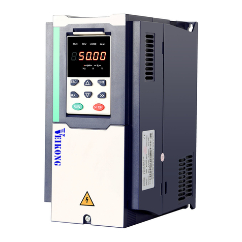
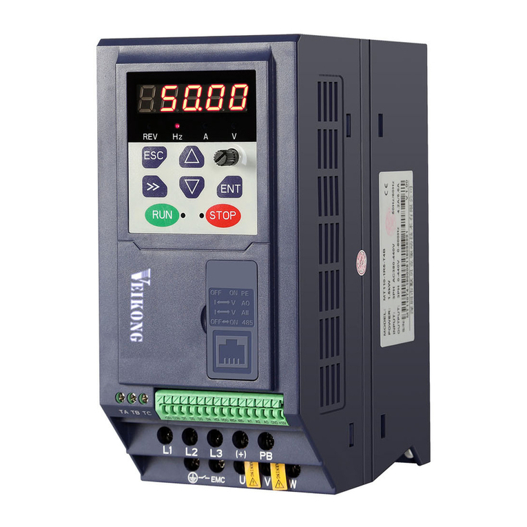
Veikong VK100 0R2G1 User manual

VK100 Series Smart Single
Phase Solar inverter
User Manual

2/ 24
1.0 Overview
1.1 Introduction
Thanks for using VK100 solar Solar pump inverter (hereinafter referred to as “this
Inverter"). Please read this operating manual carefully before usage. This operating
manual has specified the basic information regarding the installation, startup,
operation and fault diagnosis of this Inverter. Please keep this operating manual
properly for further maintenance and overhauling.
The solar photovoltaic pump system is mainly composed of solar photovoltaic pump
battery array, solar photovoltaic pump inverter and water pump. Solar photovoltaic
battery array means transmitting the solar radiation energy into DC electric energy,
which is adjusted by the photovoltaic pump inverter. The solar panel nonlinear DC
power is transmitted to the AC power which outputs continuously and complies with
the requirements of water pump motor after inversion and variable frequency
treatment. The maximum power traceability is also made to drive AC water pump
directly. The water pump motor drives impeller to pump up water.
PI150 series solar pumping system
No.
Name
Descriptions
1
Solar panels
Monocrystalline silicon, polycrystalline silicon
2
Solar pump
inverter
VK100 0R2G1, VK100 0R4G1, VK100 0R7G1,
VK100 1R1G1, VK100 1R5G1, VK10 2R2G1
3
AC water pump
Single-phase 230V AC water pump

3/ 24
The photovoltaic pump is widely used in the fields such as farmland irrigation,
irrigation of pasture livestock, ecological management of desert and barren mountain,
supply of clean domestic water for both humans and livestock, municipal sewerage
treatment, landscape fountain of urban square, water conservancy facilities and sea
water desalination, with superior performance price ratio.
1.2 Model Identification
VK 100 S 1R5 G1
Veikong inverter

4/ 24
Ordering Instruction
1. This inverter is applicable to single phase 200V~240V, 50Hz/60Hz AC motor
water pump. The load is only applicable to motor.
2. Please determine the specific power and model of the water pump according
to the hydraulic head and water yield and by consulting the water pump manufacturer
or referring to the relevant data before purchasing this Inverter.
3. The power as stated in the nameplate of water pump is generally the output
power, instead of the actual input power or motor power, either of which is generally
greater than the nominal power due to the efficiency. The power of this Inverter shall
be larger properly (this Inverter can be configured according to the motor input power
if the power has been noted); otherwise, it easily causes overload.
4. Determination of solar photovoltaic battery array power: configured according
to the requirements for water withdrawal on site; the model and power of the water
pump shall be determined according to the hydraulic head, flow, average sunlight and
wind speed. The total power of photovoltaic array is configured according to 1.5-2
times.
5. This Inverter was provided with two working modes before delivery according
to the client’s actual situations--- automatic mode and manual mode. This Inverter will
start and adjust the output power automatically under automatic mode according to
the input power of solar battery array, that is to realize the traceability of the maximum
power point. It will operate automatically to adjust the output power of this Inverter
according to the sunlight intensity; this Inverter will not drive the water pump until it is
started manually under manual mode.
6. The electric reactor shall be added to remove harmonic wave if this Inverter is
very far away from the water pump.
7.

5/ 24
Product Features
VK100 solar photovoltaic pump inverter is applicable to all industrial and
agricultural water pumps. It can resolve the problem of matching of water
pump and make the costs of system construction and maintenance lower. It is
particularly suitable in the region where electricity can not be supplied
sufficiently.
It is provided with special power tracing algorithm and the output power of the
motor can be adjusted quickly and dynamically according to the change of
sunlight intensity so as to achieve a higher utilization rate of solar energy.
It is provided with soft start function and is free from impact current so that it
can remove water hammer totally. It shall be configured with the battery panel
with small power, which can reduce the costs of solar photovoltaic pump
system dramatically.
It has high transfer efficiency and full automatic frequency conversion with the
unattended control. It is energy saving, green and environmentally friendly.
It can input solar power or power grid AC power and switch both very easily. It
enjoys ultra-wide scope of working voltage and is thus more applicable to the
different application environments of different regions.
It is provided with overvoltage, undervoltage, overload, short circuit and
lightning-proof protection and the system thus becomes safer and more
reliable.

6/ 24
2.0 Installation
2.1 Safety cautions
Safety covers the whole process of installation, trial run, operation and maintenance
of this Inverter. The incorrect use or disoperation may cause damage to the life and
personal safety of the operators and the third party as well as this Inverter. Before
installing and using this Inverter, please read all the safety cautions and warnings
listed below carefully. We bear no liabilities for the warranty of this Inverter damaged
by the failure in installing and operating it according to the contents of this manual.
This Inverter must be used in strict accordance with the statements below in order to
avoid warranty disputes:
1) It is a must to abide by the relevant electrical specifications and this manual
and have excellent electrical operation technology.The professional electrical
technicians who are familiar with the high-voltage line and electrical hazards
shall be liable for the installation and check of this Inverter. The hazards
caused by incorrect operation may cause serious injury or even death or the
hardware damage of this Inverter.
2) Please always make sure that the switch of input power is “OFF” before
connecting and overhauling this Inverter. It is of necessity to check if the
commutating capacitor of DC main bus is totally discharged by DC voltmeter
10min after the input power of this Inverter is cut off before contacting the
internal components. It would be very dangerous since power still remains
within certain period after cutting off the power.
3) It is not allowed to open the enclosure of the inversion part inside this Inverter
by those other than the manufacturer’s professionals since it easily causes
electric shock or equipment damage and makes the warranty of this Inverter
invalid. Please never open the box when it is electrified or is operated;
Otherwise, electric shock may happen. Never operate this Inverter when the

7/ 24
box is opened since it may cause electric shock by contacting the high-voltage
terminal and other electrified parts. Connection shall be made after installation;
otherwise, it easily causes electric shock or injury. It is also not allowed to
contact the output terminal of this Inverter even if this Inverter is started but
the water pump is not operated. In this circumstance, this Inverter may start
the water pump from time to time due to the change of photovoltaic input
power.
4) The voltage posed on all terminals shall be the one as stipulated in the
manual in order to avoid bursting, damage, etc. Too high voltage may damage
this Inverter very seriously or even makes it no longer available.
5) Never install this Inverter outdoors directly since it shall avoid direct sunshine.
It is not allowed to start/stop the motor with contactor without consulting the
manufacturer. The internal power can not be used for external equipment,
unless otherwise specified.
6) Pay attention to the service environment. The ambient factors such as
humidity, acid and alkaline and too high altitude all can deteriorate the
insulation of the products and easily cause electric shock or damage this
Inverter.
7) This Inverter must be grounded in strict accordance with the national and local
safety regulations and electrical specification. This Inverter can not be
grounded together with large current load such as electric welder and large
power motor but separated. The earthing wire shall be as short as possible. It
is not allowed to form earthing loop if several inverters are grounded at the
same time.

8/ 24
2.2 Mechanical Part
To make this Inverter satisfy the standards and technical specifications, this Inverter
must be installed in strict accordance with the following requirements:
1. This Inverter shall be installed vertically to ensure the cooling fin at the back of
this Inverter can transfer heat in maximum. The gap which is no shorter than
15cm shall be left on the top and at the bottom of this Inverter.
2. Sufficient space shall be left surrounding this Inverter so as to facilitate
maintenance.
3. Please use this Inverter by satisfying the following environmental conditions:
surrounding ambient temperature: -10℃~+50℃(unfrozen), surrounding
ambient humidity: below 93%RH (non-condensation); storage temperature
-20℃~+70℃(applicable temperature within short period).
4. The indoor service environment shall be free from corrosive gas, combustible

9/ 24
gas, oil mist and dust with the altitude below 2,000m ; please use this Inverter
by reducing the capacity if the altitude is above 2,000m.
5. The air shall be clean and dry. No humidity is allowed, for instance, the
condensation in wire conduit enters the box. To avoid the above, the wire
conduit shall be installed at the top of this Inverter.
2.3 Electrical Part
All the connections of this Inverter shall satisfy the national regulation (NEC) and
relevant local regulations. See the nameplate of this Inverter and motor for the
voltage and current.
2.4 Safety Cautions
1) This Inverter can input either AC or DC voltage and one input circuit breaker
(generally the circuit breaker with heat protection or the fusible isolation switch)
between the power and this Inverter shall be set. If the wire noise or
instantaneous voltage becomes too large, isolation transformer or wire reactor
can be used to provide this Inverter with input power. If the solar battery is
used to provide power to this Inverter, please always bear in mind to select the
proper voltage grade of photovoltaic battery. The working voltage grade of the
solar battery array is recommended to be 300V-350VDC and 325VDC is the
best voltage. The input open-circuit voltage of this Inverter shall be no higher
than 450VDC; otherwise, it easily causes damage to this Inverter.
2) Prior to electrical connection, it is a MUST to cover the solar battery array by
lightproof materials since the array will generate high voltage under the direct
sunshine, finally causing personal injury and death.
3) It is not allowed to start/stop the water pump by alternatively making and

10 / 24
breaking the power of this Inverter by electromagnetic starter or contactor.
This Inverter is controlled by the keyboard manually or operated and stopped
automatically.
4) The solar battery shall be provided with good lightning proof measures and
grounded reliably. The input wire shall be made with the protection equipment
that satisfies the safety standard, such as lightning proof combiner box and
DC circuit breaker. The earthing end of the input terminal is grounded.
5) The input terminal that inputs the solar battery array to this Inverter shall be
labeled with PV+ and PV-; for instance, the terminal is L/L1 and N/L2 if AC is
input; the output terminals of this Inverter U/T1 and V/T2 (U/T1, V/T2 and
W/T3 are the output terminals of this Inverterif it is 3-phase 230V) are
connected with the motor directly. It is prohibited to install static condenser,
surge filter and wireless noise filter at the output side of this Inverter since this
will damage this Inverter.
It also may damage the capacitor and surge filter.
6) The load other than single phase squirrel cage motor is prohibited. The
equipment may be damaged if connecting other electrical equipment with the
output of this Inverter.
7) If the residual current circuit breaker is set for the protection of leakage fault of
this Inverter, please select the one with sensitivity current above 200mAand
the action time above 0.1s in order to avoid the fault operation of it.
8) Please connect the water shortage and overflow sensors of this Inverter
correctly and make the corresponding signals valid. The error water shortage
sensor connection or settings may make the water pump idle without water,
causing serious wearing or burning. The error overflow sensor connection or
settings may cause the water tank at the water side overflow.
Warning:This Inverter will be damaged if connecting the input power line to
U/T1 and V/T2 terminals (or U/T1, V/T2, W/T3 terminals). Please make sure the
correctness of input and output connection!

11 / 24
2.5 Cautions for safety use
When this Inverter drives the water pump, please see to it that the insulation
capacity and voltage drop shall be evaluated carefully when the motor is 50m longer
from the wiring of this Inverter. If necessary, the special output reactor of this Inverter
shall be set.
2.6 Connection
Power terminal:
E
P+
P-
L1/L
L2/N
U/T1
V/T2
Note: E refers to the earthing terminal of inverter enclosure and the power input
of solar panels is connected with L1/L and L2/N,(If it is solar and power automatic
switching models, then connected with P+ and P- terminals and single phase 230V
AC power is connected with L1/L and L2/N terminals).
Solar and power automatic switching models are options
U/T1, V/T2 are the output terminals of this Inverter and shall be connected with the
motor. It is prohibited to connect the input and output terminals of the inverter
reversely; otherwise, it may damage the internal parts of the inverter.
Control terminal:
COM
PR1
PR2
OF
LW
COM
RA
RB
Note:It is prohibited to connect or use the reserved terminals without the
manufacturer’s permit.

12 / 24
Functions of control terminal
Category
Terminal
signal
Terminal
name
Terminal function
Remarks
Power
terminal
L1/L,
L2/N
Input terminal
of solar power
Power connecting
solar panels
Pay attention
to the input
and output to
avoid
connection
P+, P-
U/T1,
V/T2,
Output
terminal of
inverter
Output connects
motor
E
Earthing
terminal
Earthing
Control
terminal
of input
signal
PR1
Control
terminal
Input of optical
sensor
PR2
Control
terminal
Input of optical
sensor
OF
Control
terminal
Input of detection
signal of overflow
(drainage) water
level sensor
LW
Control
terminal
Input of detection
signal of supply
water level sensor
COM
Control
terminal
COM is the public
terminal of all
control terminals
Reserved
input
terminal
RE1
AU
SP
+24V
Output
signal
terminal
RA
RAand RB
are normally
open contacts
of the relay
Relay outputs
normally open
contacts
RAand RB
are closed
after the
operation of
this Inverter
RB
COM is the public terminal while LW and COM are the terminals for the water
shortage protection interfaces. Both can be connected with the water level monitoring
sensor of the water source. The sensor type can be set by parameters (if it is set as
FHH, the disconnection of the sensor is valid; for the protection when the sensor is

13 / 24
connected, such as FLL, the connection of the sensor is valid. It does protect if the
sensor is disconnected). OF and COM are overflow protection interface terminals and
are connected with the water level monitoring sensor of the waterstorage device. The
type of sensor can be set by parameters (if it is set as U HH, the disconnection of the
sensor is valid; for the protection when the sensor is connected, such as U LL, the
connection of the sensor is valid. It does protect if the sensor is disconnected). PR1
and PR2 are connected with the input of optical sensor. RA and RB are a pair of
normally open contacts of the relay (the overload capacity of contact: 1A/230VAC), It
is connected after the operation of this Inverter.
3.0 Panel and Operation Instructions
The operation panel is used to display the operation of this Inverter, start the water
pump under special circumstance or set parameters.
RUN:
it means operation if the red lamp is on.
STOP:
it means stop if the red lamp is on.
Display area
Display of the output frequency,
status and the set value of all
parameters
Function display area
Display of the status of this
Inverter and parameter settings
Operation/stop key
OK key
Confirm by pressing this key after
modifying parameters
Up/down key
Resetting after Parameter modification
and abnormal alarm

14 / 24
Descriptions of Contents Displayed
Display
Instruction
Display
Instruction
The lower limit voltage of
power tracking of this
Inverter is 200V
The starting
voltage of this
Inverter is
300V
This Inverter can be started
in 50min after the alarming
of this Inverter due to the
detection of water level
The output of
water level
detection
sensor of water
pump is
disconnected
(LL means
valid
connection)
The output of overflow
sensor of water pump is
connected (HH means
valid disconnection)
This Inverter is
under manual
operation
mode
This Inverter is under
automatic operation mode
The rated
frequency of
the water
pump is 50Hz
This Inverter will operate
automatically in 60s
The operation
frequency of
the water
pump is 50Hz
The input voltage is 360V

15 / 24
Operating Instruction of Keyboard
Selection of monitoring interface:
Parameter settings and modification
The water pump can be started in the delay time set after the water level alarming
occurs under general circumstances. It is unnecessary to wait by pressing up/down
key at the same time after water level alarming occurs.
4.0 Parameters
The parameters that may need adjusting in installation and usage are shown in the
table below:
No.
Parameters
Parameter functions
Scope of setting
Delivery
value
1
CXXX
Lower limit of MPPT
voltage
DC180~300V
230V
2
HXXX
Starting voltage
DC260~360V
280V
3
P XX
Delayed starting
time after water
level alarming
4~80min
30min
4
F XX
Output type of water
level sensor of water
HH: normally
opened, LL:
HH

16 / 24
supply
normally closed
5
U XX
Output type of water
level sensor of water
storage
HH: normally
opened, LL:
normally closed
HH
6
RUN
AUTO
Working mode of
this Inverter
RUN: manual
working mode
AUTO: automatic
working mode
RUN
7
J XX
Selection of rated
frequency of water
pump
J 50: 50Hz, J60:
60Hz
50Hz
Note! The starting voltage or the lower limit of MPPT voltage can not be set
successfully until the starting voltage is 30V higher than the lower limit of MPPT
voltage.
Never adjust the parameters arbitrarily unless the professionals have fully understood
the effect after parameter adjustment; adjustment shall be made gradually to avoid
fault or accident due to excessive adjustment. The parameters that are not listed in
the table are the factory parameters which shall not be adjusted arbitrarily unless the
factory informs it clearly.
If “LL” or “OF” alarming happens to this Inverter, it can not be started
again until the water level sensor or the output signal recovers to be
normal and the delayed time set by parameter “PXX” and the input
power satisfy the starting conditions. It is unnecessary to wait by
pressing up/down key on the panel at the same time.If “LL” or “OF”
alarming happens to this Inverter, “END” will be displayed followed by
“IDLE” and this Inverter will be under idle status by pressing up/down
key on the panel at the same time under manual working mode after
the sensor is recovered to be normal (including normal setting). It can
be started manually if the input power satisfies the conditions; if
pressing up/down key on the panel at the same time under automatic
mode, "END” will be displayed followed by “L60” as long as the input

17 / 24
power satisfies the starting conditions. The water pump will start to
operate automatically in 60s.
5.0 Trial Run
Note! Please operate by adhering to the following steps and check if the data are
normal after the installation and connection of the equipment but before the first
operation.
This Inverter shall be generally installed and debugged in sunny weather so that the
solar battery pack can output sufficient energy and normal operation of the user’s
photovoltaic pump system can be ensured. This Inverter shall be made to operate
with high power.
※Check if the photovoltaic array, combiner box and installation of photovoltaic cable
comply with the requirements.
※Check if the water pump inverter satisfies the installation and connection
requirements.
※Check if the water pump and pipeline satisfy the operation requirements.
※Adjust the photovoltaic battery array to the best position.
※Check if the voltage and polarity of photovoltaic input terminal comply with the
requirements.
※If no water shortage or overflow sensor is used on site, the output type of two
corresponding sensors shall be HH (the delivery setting is HH). Please use water
shortage and overflow sensor and make the signal valid to protect the safe operation
of the system.
※Check if the optical sensor can sense the sunlight fully (installed with the battery
panel without being covered). PR1 and PR2 short circuit is required if there is no
optical sensor.
※Connect DC circuit breaker and set thecorresponding parameters according to the

18 / 24
actual situations.
※Press “RUN/STOP” key on the inverter panel manually to operate this Inverter and
the system will start to work. Check if the photovoltaic pump system works normally
and reach the system hydraulic head and flow. Press “RUN/STOP” key on the
inverter panel after operation for certain period to shut down this Inverter.
Note: This Inverter will not start automatically after shutdown under manual working
mode.
It means the phenomenon where the water can not be pumped or the
flow fails to reach the designed value in trial operation. This may be caused by the
following factors:
Too small power output by solar battery array;
Unreasonable design of photovoltaic pump system.
6.0 Automatic Operation
After the equipment is installed and connected and the inverter power is on, the
photovoltaic battery array starts to supply power after sunrise and this Inverter will
turn on automatically again without the necessity of artificial operation. This Inverter
will be started and operated according to the steps below:
a) The power switch of this Inverter is on, DC circuit breaker is connected and the
selector switch is at the photovoltaic driven side.
b) The photovoltaic battery array starts to generate power and this Inverter starts to
supply power.
c) System self-inspection. The water pump will start to operate in 1min after the

19 / 24
photovoltaic power input satisfies the water outlet conditions; otherwise, it will keep
waiting or switch to the mains supply for operation automatically.
Note: The power switch shall be also connected during the process of automatic
operation and the input end of the solar photovoltaic battery will turn on automatically
after the sunrise. The water pump can operate automatically as long as the operation
conditions can be satisfied. This Inverter will restart to operate again if the starting
conditions can be met even if by pressing “RUN/STOP” key on the panel under
automatic mode to shut it down.
As for the machine that can switch between solar energy and
electric supply, the electric supply will be used automatically if the power of solar
photovoltaic battery is not enough to drive the water pump to yield water. If, however,
the power of the photovoltaic battery is able to satisfy the yielding requirements of
water pump when the electric supply is used, this Inverter will switch to the solar
battery automatically. In other words, the solar battery shall be prioritized. In this way,
the utilization rate of solar battery becomes higher and the water pump can work in
the daytime and at night without battery. It reduces the system costs and expands the
application scope of water pump.
It is prohibited to shut down the water pump by disconnecting the
inverter input when the pump is operated. Instead, cut off the inverter input
after this Inverter stops output; otherwise, it is easy to damage this Inverter.

20 / 24
7.0 Fault News and Countermeasures
This Inverter is provided with several kinds of warning information and protection
function. The protection function of this Inverter will work, this Inverter will stop
outputting and water pump will stop operating automatically when fault happens.
Please resolve the problem by comparing the abnormal contents displayed of this
Inverter and the cause and troubleshooting or contact the manufacturer for technical
support by +8615112278465.
7.1 The water pump will be unable to start or operate if this Inverter displays “LL”
alarming.
Cause:
a) The water level sensor of water supply works.
b) The output type parameter “F XX” of water level sensor of water supply is set by
mistake.
c) The water pump is under restart delay status.
Check focus and countermeasures:
a) Check the water level to see if water is urgently required.
b) The parameters shall be set again: “F XX” shall be made to be in consistency with
the type of the water level sensor applied.
c) Resetting shall be made by pressing up/down key on the panel at the same time to
cancel the restarting delay or wait the delay time set.
7.2 The water pump will be unable to start or operate if this Inverter displays “OF”
alarming.。
Cause:
a) The overflow water level sensor of the water storage device works.
b) The output type parameter “U XX” of water level sensor of water storage device is
set by mistake.
This manual suits for next models
5
Table of contents
Other Veikong Inverter manuals

Veikong
Veikong VFD500-PV Series User manual

Veikong
Veikong VFD700-PV-40T00075 User manual

Veikong
Veikong VFD500 Series User manual

Veikong
Veikong VFD500-PV Series User manual

Veikong
Veikong VFD700 Series User manual

Veikong
Veikong VFD500M Series User manual

Veikong
Veikong VFD530 User manual

Veikong
Veikong VFD500-PV Series User manual
Popular Inverter manuals by other brands

HP
HP 83522A Service notes

Generac Power Systems
Generac Power Systems 7 kW NG Installation and owner's manual

Siemens
Siemens micromaster 410 operating instructions

enphase
enphase M215 Installation and operation manual

Victron energy
Victron energy Phoenix 12/225 user manual

Tigo
Tigo EI ATS 200A quick start guide