Veikong VFD500M Series User manual

VFD500M Series
ShenZhen VEIKONG Electric CO., Ltd.
High performance smart Inverter
User Manual
ShenZhen VEIKONG Electric CO., Ltd.
Factory Address:
Block E01,first industrical park lingbei 5 road ,phoenix comm
unity,fuyong street , Bao'anDistrict, Shenzhen ,China
R&D Center: Jin yu cheng building A,Bu Long Rd Bantian Town
,Longgang district Shenzhen City,China
Technical Support Hotline: +86-0755-89587650
Web Site: www.veikong-electric.com
Whatsapp +8615989436541

Preface
Thank you for purchasing the VFD500M series high performance vector and torque control frequency
inverter
VFD500M is a economical vector control inverter for asynchronous motor control .High reliability, easy to
use, compact size and rich functions; support open-loop VF control and speed sensorless vector control,
can be used for driving various automatic production equipment
This manual introduces functional characteristics and usage of VFD500M series inverter, includes product
model selection, parameter settings, running and debugging, maintenance, checking, and so on. Please
be sure to read this manual carefully before operation. For equipment matching manufacturers, please
send this manual to your end user together with your devices, in order to facilitate the usage.
PRECAUTIONS
◆To describe the product details, the illustrations in the manual sometimes are under the state of
removing the outer housing or security covering. While using the product, please be sure to mount
the housing or covering as required, and operate in accordance with the contents of manual.
◆The illustrations in this manual is only for explanation, may be different from the products you
ordered.
◆Committed to constantly improving the products and features will continue to upgrade, the
information provided is subject to change without notice.
◆Please contact with the regional agent or client service center directly of factory if there is any
questions during usage.
EDIT: V1.1
TIME: 2020-10
1

Contents
Chapter 1 Safety Information and Precautions.......................................................................................... 1
1.1 Safety Precautions........................................................................................................................... 1
1.2 Precaution......................................................................................................................................... 2
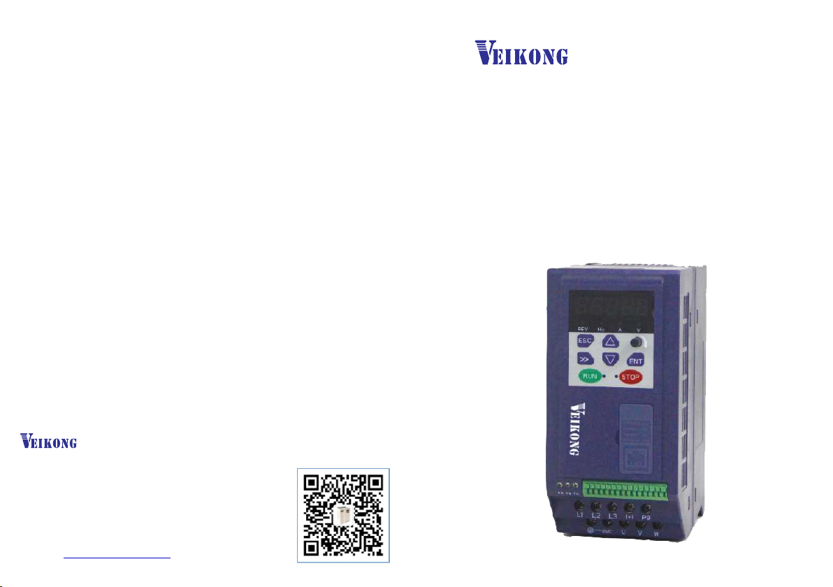
Chapter 2 Product Information ..................................................................................................................... 4
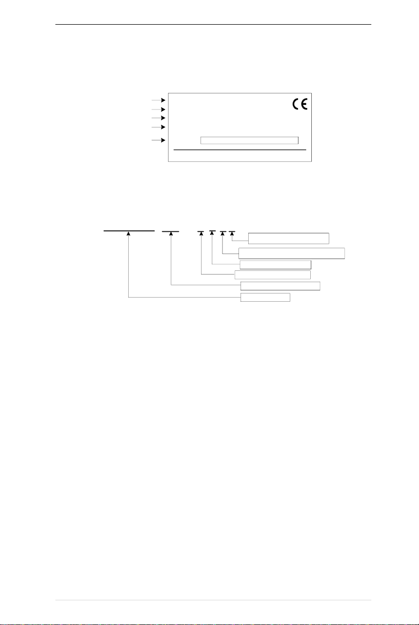
2.1 Designation Rules............................................................................................................................ 4
2.2Product series instruction ................................................................................................................ 4
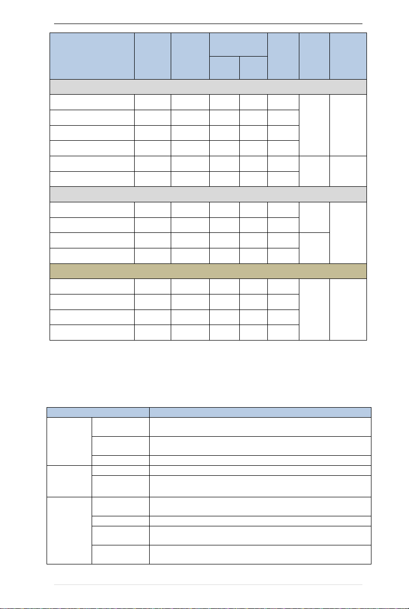
2.3Technical Specifications................................................................................................................... 5
Chapter 3 Product appearance and Installation Dimension.......................................................... 8
3.1 Product appearance and installation............................................................................................. 8
3.1.1Product appearance .............................................................................................................. 8
3.1.2Appearance and Mounting Hole Dimension...................................................................... 8
3.2Wiring.................................................................................................................................................. 9
3.2.1 Standard wiring diagram...................................................................................................... 9
3.2.2Main Circuit Terminals......................................................................................................... 10
3.2.3 Terminal screws and wiring specifications ...................................................................... 11
3.2.4 Cautions for Main Circuit Wiring....................................................................................... 11
3.2.5Control Circuit Terminal....................................................................................................... 12
4.1 LED Instruction of operation and display................................................................................. 16
4.2 Digital tube display...................................................................................................................... 17
Chapter 5 Function Code Table.................................................................................................................. 19
Chapter 6 Fault Diagnosis and Solution ................................................................................................... 84
6.2 Warning type................................................................................................................................... 90
Chapter 7 Daily maintenance of frequency inverters.............................................................................. 91
8.1 Daily maintenance ......................................................................................................................... 91
8.1.1 Daily maintenance .............................................................................................................. 91
8.1.2 Regular inspection.............................................................................................................. 91
8.2 Wearing parts replacement .......................................................................................................... 91
8.3Warranty Items ................................................................................................................................ 92
Appendix A Modbus communication protocol ....................................................................................... 93
2

VFD500M vector control frequency inverter user manual Chapter 1 Safety information and precautions
Chapter 1 Safety Information and Precautions
Safety Definitions: In this manual, safety precautions are divided into the following two categories:
indicates that failure to comply with the notice will result in serous injury or even death
indicates that failure to comply with the notice will result in moderate or minor injury
andequipment damage
Read this manual carefully so that you have a thorough understanding. Installation, commissioning or
maintenance may be performed in conjunction with this chapter. will assume no liability or responsibility
for any injury or loss caused by improper operation.
1.1 Safety Precautions
Use stage
Security Level
Precautions
Before
Installation
DANGER
➢packing water, parts missing or damaged parts, please do not install!
➢Packaging logo and physical name does not match, please do not
install!
WARNING
➢Handling should be light lift, otherwise there is the danger of damage
to equipment!
➢Do not use damaged drive or missing drive. Risk of injury!
➢Do not touch the control system components by hand, or there is the
danger of electrostatic damage!
During
Installation
DANGER
➢Please install the flame retardant objects such as metal, away from
combustibles, or may cause a fire!
WARNING
➢Do not allow lead wires or screws to fall into the drive, otherwise the
drive may be damaged!
➢Install the drive in a place where there is less vibration and direct
sunlight.
➢Drive placed in airtight cabinet or confined space, please note the
installation of space to ensure the cooling effect.
Wiring
DANGER
➢You must follow the guidance of this manual and be used by qualified
electrical engineers. Otherwise, unexpected danger may occur!
➢There must be a circuit breaker between the drive and the power
supply, otherwise a fire may occur!
➢Make sure the power supply is in zero-energy state before wiring,
otherwise there is danger of electric shock!
➢Please follow the standard to the drive properly grounded, otherwise
there is the risk of electric shock!
WARNING
➢Never connect input power to the drive's output terminals (U, V, W).
Note that the terminal markings, do not take the wrong line! Otherwise
it will cause damage to the drive!
➢Never connect the braking resistor directly to the DC bus +, -
terminals. Otherwise it will cause a fire!
➢Refer to the manual's recommendations for the wire diameter used.
Otherwise it may happen accident!
➢Do not disassemble the connecting cable inside the driver. Otherwise,
the internal of the servo driver may be damaged.
Before
Power-on
DANGER
➢Make sure the voltage level of the input power is the same as the
rated voltage of the driver. Check if the wiring position of the power
input terminals (R, S, T) and output terminals (U, V, W) is correct; Of
3

VFD500M vector control frequency inverter user manual Chapter 1 Safety information and precautions
Use stage
Security Level
Precautions
the external circuit is short-circuited, the connection is tightened, or
cause damage to the drive!
➢No part of the drive need to withstand voltage test, the product has been
made before the test. Otherwise it may cause accident!
WARNING
➢The driver must be covered before the cover can be powered,
otherwise it may cause electric shock!
➢All peripheral accessories must be wired according to the instructions
in this manual, and be properly wired in accordance with this manual.
Otherwise it may cause accident!
After Power-
on
DANGER
➢Do not open the cover after power on, otherwise there is danger of
electric shock!
➢If the indicator light does not light after power on, the keyboard does
not display the situation, immediately disconnect the power switch, do
not touch any input and output terminals of the drive, otherwise there is
the risk of electric shock!
WARNING
➢If parameter identification is required, preclude the possibility of injury
when rotating the motor!
➢Do not arbitrarily change the drive manufacturer parameters, or it may
cause damage to the device!
During
Operation
DANGER
➢Do not touch the cooling fan, radiator and discharge resistance to test
the temperature, otherwise it may cause burns!
➢Non-professional technicians Do not detect the signal during operation,
otherwise it may cause personal injury or equipment damage!
WARNING
➢Drive operation, should avoid something falling into the device,
otherwise it will cause damage to the device!
➢Do not use the contactor on-off method to control the start and stop
the drive, otherwise it will cause damage to the equipment!
Maintenance
DANGER
➢Do not live on the equipment repair and maintenance, or there is a
risk of electric shock!
➢Turn off the input power for 10 minutes before performing
maintenance and repair on the drive, otherwise the residual charge on
the capacitor will cause harm to people!
➢Do not carry out maintenance and repair on the drive without
personnel who have been professionally trained, otherwise personal
injury or equipment damage will occur!
➢All pluggable plug-ins must be unplugged in the case of power failure!
➢The parameters must be set and checked after replacing the drive.
WARNING
➢Before performing maintenance work on the drive, make sure that the
motor is disconnected from the drive to prevent the motor from feeding
back power to the drive due to accidental rotation.
1.2 Precaution
⚫Contactor using
If the contactor is installed on the power input side of the inverter, do not make the contactor frequent on-off
operation. The interval between ON and OFF of the contactor should not be less than one hour. Frequent
charging and discharging will reduce the use of capacitors in the inverter life.
If a contactor is installed between the inverter output terminals (U, V, W) and the motor, make sure that the
inverter is turned on and off when there is no output. Otherwise, the inverter may be damaged.
⚫Lightning impulse protection
Although this series of inverters are equipped with lightning over-current protection device, there is a certain
degree of self-protection for inductive lightning, but for lightning frequent place, customers should also install
lightning protection device in the front of the inverter.
4

VFD500M vector control frequency inverter user manual Chapter 1 Safety information and precautions
⚫Altitude and derating use
In areas above 1000m above sea level, it is necessary to derate the inverter due to poor air quality due to poor
air quality. In this case, please consult our company.
⚫Power input
The inverter power input should not exceed the operating voltage range specified in this manual. If necessary,
use a step-up or step-down device to change the power supply to the specified voltage range.
Do not change the three-phase inverter to two-phase input, otherwise it will cause malfunction or inverter
damage.
⚫Output filtering
When the cable length between the inverter and the motor exceeds 100 meters, it is suggested to use the output
AC reactor to avoid inverter over-current caused by excessive distributed capacitance. Output filter according
to the needs of the field matching.
Inverter output is PWM wave, please do not install the capacitor on the output side to improve the power factor
or lightning varistor, etc., otherwise it may easily lead to inverter instantaneous overcurrent or even damage the
inverter.
⚫About motor heat and noise
Because the inverter output voltage is PWM wave, contains a certain degree of harmonics, so the motor
temperature rise, noise and vibration compared with the same frequency operation will be slightly increased.
⚫Disposal
Electrolytic capacitors on the main circuit and electrolytic capacitors on the printed circuit board may explode
when incinerated, and poisonous gases are generated when plastic parts are burned. Please dispose as
industrial waste.
⚫The scope of application
This product is not designed and manufactured for use on equipment where life is at stake. To use this
product on a mobile, medical, aerospace, nuclear or other special purpose device, please contact our company For
more information.
This product is manufactured under strict quality control and should be equipped with a safety device if it is
used in a device that may cause a serious accident or damage due to inverter failure.
5

VFD500M vector control frequency inverter user manual Chapter 2 Product information
Chapter 2 Product Information
2.1 Designation Rules
Name plate:
MODEL: VFD500M-2R2GT4B
POWER: 2.2kW/4.0kW
INPUT: 3PH AC380~440V 50Hz/60Hz
OUTPUT: 3PH 0~440V 0~600Hz 5.6A/9.4A
S/N:
TYPE
POWER
INPUT
OUTPUT
CODE
2-1 name plate
Model instruction:
2-2model instruction
2.2Product series instruction
Table 2-1VFD500M inverter models and technical data
VFD500M -2R2 –G T 4 B
T:three phase
Load type:G normal duty
Power,2R2 means 2.2kW
Product series
B means breaking units
4:380-480v three phase 2: 200-240v
6

VFD500M vector control frequency inverter user manual Chapter 2 Product information
Model
Power
capacity
(KVA)
Input
current
(A)
Output
current(A)
Adapt
able
Motor
(KW)
SIZE
Brake
Unit
Heavy
load
Light
load
3 phase: 380V-480V,50/60Hz
VFD500M-R75GT4B
1.6
3.2
2.5
4.2
0.75
SIZE B
Internal
VFD500M-1R5GT4B
2.8
4.7
4.2
5.6
1.5
VFD500M-2R2GT4B
3.7
7.8
5.6
9.4
2.2
VFD500M-4R0GT4B
6.2
11.6
9.4
10.5
3.7
VFD500M-5R5GT4B
8.6
15.6
13.0
17.0
5.5
SIZE C
Internal
VFD500M-7R5GT4B
11.2
20.5
17.0
23.0
7.5
1 phase: 200-240V,50/60Hz
VFD500M-R40GS2B
1.2
6.9
2.8
3.2
0.4
SIZEA
Internal
VFD500M-R75GS2B
2.1
12.2
4.5
4.8
0.75
VFD500M-1R5GS2B
3.1
17.0
8.0
10.6
1.5
SIZEB
VFD500M-2R2GS2B
4.1
21.0
10.6
12.5
2.2
3 phase: 200V-240V,50/60Hz
VFD500M-R40GT2B
1.2
4
2.8
3.2
0.4
Size B
Internal
VFD500M-R75GT2B
2.1
7.1
4.5
4.8
0.75
VFD500M-1R5GT2B
3.1
11.3
8.0
10.6
1.5
VFD500M-2R2GT2B
4.1
14.5
10.6
12.5
2.2
2.3Technical Specifications
Table 2-2 VFD500M Technical Specifications
Item
Specifiation
Input
Inuput Voltage
1phase/3phase 220V:200V~240V
3 phase 380V-480V:380V~480V
Allowed Voltage
fluctuation range
-15%~10%
Input frequency
50Hz / 60Hz,fluctuation less than 5%
Output
Output Voltage
1/3phase:0~input voltage
Overload capacity
General purpose application:60S for 150% of the rated current
Light load application:60S for 120% of the rated current
Control
Control mode
V/f control
Sensorless flux vector control without PG card(SVC)
Operating mode
Speed control、Torque control(SVC)
Speed range
1:100 (V/f)
1:200( SVC)
Speed control
accuracy
±0.5% (V/f)
±0.2% (SVC)
7

VFD500M vector control frequency inverter user manual Chapter 2 Product information
Speed response
5Hz(V/f)
20Hz(SVC)
frequency range
0.00~600.00Hz(V/f)
0.00~200.00Hz(SVC)
Input frequency
resolution
Digital setting: 0.01 Hz
Analog setting: maximum frequency x 0.1%
Startup torque
150%/0.5Hz(V/f)
180%/0.25Hz(SVC)
Torque control
accuracy
SVC:within 5Hz10%,above 5Hz5%
VC:3.0%
V/f curve
V / f curve type: straight line, multipoint, power function, V / f
separation;
Torque boost support: Automatic torque boost (factory setting), manual
torque boost
Frequency giving
ramp
Support linear and S curve acceleration and deceleration;
4 groups of acceleration and deceleration time, setting range 0.00s ~
60000s
DC bus voltage
control
Overvoltage stall control: limit the power generation of the motor by
adjusting the output frequency to avoid skipping the voltage fault;
Undervoltage stall control: control the power consumption of the motor
by adjusting the output frequency to avoid yaw failure
VdcMax Control: Limit the amount of power generated by the motor by
adjusting the output frequency to avoid over-voltage trip;
VdcMin control: Control the power consumption of the motor by
adjusting the output frequency, to avoid jump undervoltage fault
Carrier frequency
1kHz~16kHz(Varies depending on the type)
Startup method
Direct start (can be superimposed DC brake); speed tracking start
Stop method
Deceleration stop (can be superimposed DC braking); free to stop
Maincontrol
function
Jog control, droop control, up to 16-speed operation, dangerous speed
avoidance, swing frequency operation, acceleration and deceleration
time switching, VF separation, over excitation braking, process PID
control, sleep and wake-up function, built-in simple PLC logic, virtual
Input and output terminals, built-in delay unit, built-in comparison unit
and logic unit, parameter backup and recovery, perfect fault
record,fault reset, two groups of motor parametersfreeswitching,
software swap output wiring, terminals UP / DOWN
Function
Keypad
LED Digital keypad and LCD keypad(option)and external LED display
communication
Standard:
MODBUS communication
Input terminal
Size A:4 digital input terminals and 1 analog input terminals
Size B:5 digital input terminals,one of which supports high-speed pulse
input up to 50kHz;2 analog input terminalssupport 0 ~ 10V voltage input
or 0 ~ 20mA current input;
Output terminal
Size A 1 digital output terminal;
1 relay output terminal(Support NO only )
1 analog output terminals, support 0 ~ 20mA current output or 0 ~ 10V
voltage output;
Size B 1 digital output terminal;
1 high-speed pulse output terminal (open collector type), support
0 ~ 50kHz square wave signal output;
1 relay output terminal(SUPPORT NO AND NC)
1 analog output terminals, support 0 ~ 20mA current output or 0 ~
10V voltage output;
Protection
Refer to Chapter 6 "Troubleshooting and Countermeasures" for the protection function
Environment
Installation
location
Indoor, no direct sunlight, dust, corrosive gas, combustible gas, oil
8

VFD500M vector control frequency inverter user manual Chapter 2 Product information
smoke, vapor, drip or salt.
Altitude
0-3000m.inverter will be derated if altitude higher than1000m and
rated output current will reduce by 1% if altitude increase by 100m
Ambient
temperature
-10°C~ +40°C,maximum 50°C (derated if the ambient temperature is
between 40°C and 50°C)Rated output current decrease by 1.5% if
temperature increase by 1°C
Humidity
Less than 95%RH, without condensing
Vibration
Less than 5.9 m/s2 (0.6 g)
Storage
temperature
-20°C ~ +60°C
Others
Installation
Wall-mounted, floor-controlled cabinet, transmural
Protection level
IP20
cooling method
Forced air cooling FOR SIZE B ,SIZE A(NATURAL COOLING)
9

Chapter 3 Product appearance VFD500M vector control frequency inverter user manual
Chapter 3 Product appearance and Installation Dimension
3.1 Product appearance and installation
3.1.1Product appearance
3.1.2Appearance and Mounting Hole Dimension
Remark: Φd is screw hole diameter for installing
Table 3-1 VFD500M series appearance and installation dimension
SIZE TYPE
Appearance and installation dimension(mm)
A
B
H
W
D
Φd
Mounting
screws
SIZE A
66
137
145
75
115
ø5.0
M4×16
SIZE B
72
165
175
86
128
ø5.0
M4×16
SIZE C
108
225
235
120
158
ø5.0
M4×16
10

Chapter 3 Product appearance VFD500M vector control frequency inverter user manual
3.2Wiring
3.2.1 Standard wiring diagram
Braking Resistor
M
U
V
W
R/L1
S/L2
T/L3
3PH AC power input
DI1
DI2
DI3
DI4
GND
485+
485-
RS485 port
GND
AO output:
0~10V/0~20m
A
T1A
T1C
Digital input1
Digital input2
Digital input3
Digital input4
FWD
REV
+PB
DO
COM Open collector
output
AO
380V~ 50/60Hz
Relay 1 output
breake
rreactor
Main circuit
Control circuit
PC
AI1
Analog input
0~10V/0~2
0mA GND
VI V
OFF
I
ON
ONOFF PE
AO
AI1
485
Twisted
cable
shield
Note
:
Figure 3-2 (SIZE A) standard wiring diagram
Braking resistor
M
U
V
W
R/L1
S/L2
T/L3
3PH AC power input
DI1
DI2
DI3
DI4
COM
AI2
GND
485+
485-
RS485 port
GND
AO output:
0~10V/0~20m
A
T1A
T1C
T1B
Digital input1
Digital input2
Digital input3
Digital input4
+10V
24V
FWD
REV
+PB
HDI
High speed pulse input HD
O
COM
Open collector output
High speed pulse output
AO
380V~ 50/60Hz
1~5k Relay 1
output
VI V
OF
F
I
ON
O
N
OF
F
breake
rreactor
Main circuit
Control circuit
PE
PC
AO
AI1
485
Twisted
cable
shield
Not
e:
AI1
Analog input
0~10V/0~2
0mA GND
Figure 3-3 (SIZE B/C) standard wiring diagram
11

Chapter 3 Product appearance VFD500M vector control frequency inverter user manual
3.2.2Main Circuit Terminals
Figure 3-4 SIZE A main circuit terminal diagram
Figure 3-5 SIEZ B main circuit terminal diagram
Figure 3-6 SIEZ C main circuit terminal diagram
Table 3-2 Function description of the main circuit terminal of the inverter
Terminal
Function instruction
L1、L2、L3
AC power input terminal, connect three-phase AC power(only
L1/L2 is single phase inverter)
U、V、W
Inverter AC output terminal, connect three-phase AC motor
(+)、PB
Braking resistor connection terminal when built-in brake unit
Ground terminal, ground
EMC
Safety capacitor and varistor grounding selection screw
12

Chapter 3 Product appearance VFD500M vector control frequency inverter user manual
3.2.3 Terminal screws and wiring specifications
Table 3-3 Main circuit cable and screw specifications
Model number
Power terminal
Ground terminal
Scre
w
Tightening
torque
(Nm)
Cable
diameter
(mm2)
scre
w
Tightening
torque
(Nm)
Cable
diameter
(mm2)
3 phase voltage: 380V,50/60Hz
VFD500M-R75GT4B
M4
2
2.5
M4
2
2.5
VFD500M-1R5GT4B
M4
2
2.5
M4
2
2.5
VFD500M-2R2GT4B
M4
2
2.5
M4
2
2.5
VFD500M-4R0GT4B
M4
2
4
M4
2
4
VFD500M-5R5GT4B
M4
2
6
M4
2
6
VFD500M-7R5GT4B
M4
2
6
M4
2
6
Single phase voltage: 220V,50/60Hz
VFD500M-R40GS2B
M3
1.5
2.5
M3
1.5
2.5
VFD500M-R75GS2B
M3
1.5
2.5
M3
1.5
2.5
VFD500M-1R5GS2B
M4
2
2.5
M4
2
2.5
VFD500M-2R2GS2B
M4
2
4.0
M4
2
4.0
3.2.4 Cautions for Main Circuit Wiring
(1)Power Supply Wiring
◆ It is forbidden to connect the power cable to the output terminal of the inverter. Otherwise, the internal components
of the inverter will be damaged.
◆ In order to provide input side overcurrent protection and power outage overhaul convenience, the inverter should
be connected to the power supply through circuit breakers and contactors.
◆ Please confirm the power phase, the voltage is consistent with the product nameplate, do not match may result
in damage to the inverter.
(2)DC wiring
◆ Do not connect the braking resistor directly to +, -, which may cause the inverter to be damaged or
even fire.
◆ When using the external brake unit, pay attention to +, - can not be reversed, otherwise it will cause
damage to the inverter and brake unit or even cause a fire.
(3)Motor Wiring
◆It is forbidden to short circuit or ground the inverter output terminal, otherwise the internal components
of the inverter will be damaged.
◆Avoid short circuit the output cables or with the inverter enclosure, otherwise there exists the danger of
electric shock.
13

Chapter 3 Product appearance VFD500M vector control frequency inverter user manual
◆It is forbidden to connect the output terminal of the inverter to the capacitor or LC/RC noise filter with
phase lead, otherwise, the internal components of the inverter may be damaged.
◆When contactor is installed between the inverter and the motor, it is forbidden to switch on/off the
contactor during the running of the inverter, otherwise, there will be large current flowing into the inverter,
triggering the inverter protection action.
◆Length of cable between the inverter and motor
If the cable between the inverter and the motor is too long, the higher harmonic leakage current of the
output end will produce by adverse impact on the inverter and the peripheral devices. It is suggested
that when the motor cable is longer than 100m, output AC reactor be installed. Refer to the following
table for the carrier frequency setting.
3.2.5Control Circuit Terminal
GND DI1 DI2 DI3 DI4 DO 485+ 485- AI1 AOTA TC
485
AO
PE
AI1
K1
Jumper
switch V
IV
OFF
I
ON
ON
OFF
GND +10V
Keypad
Port
System
reservation
Figure 3-6 Schematic diagram of the VFD500M control circuit terminal (SIZE A)
+24V COM DI1 DI2 DI3 DI4 HDI HDO 485+ 485- AI1 AI2 AOTA TB TC
485
AO
PE
AI1
K1
Jumper
Switch V
IV
OFF
I
ON
ON
OF
F
GND +10V
Keypad
port
System
reservation
Figure 3-6 Schematic diagram of the VFD500M control circuit terminal (SIZE B/C)
14

Chapter 3 Product appearance VFD500M vector control frequency inverter user manual
Table 3-3 VFD500M control circuit terminal instruction
Type
Terminal
Symbol
Terminal
Name
Terminal function description
Analog input
voltage
+10V
Input voltage
10.10V±1%
Maximum output current:10mA,it provides power
supply to external potentiometer with resistance range
of:1KΩ~51KΩ
GND
Ananog
ground
Internal isolation from COMThe factory PE and GND
safety capacitors are OFF by default.
AI1
Analog input1
Input voltage:0~10V:Impedance 22KΩ,Maximum
input voltage
Input current:0~20mA:Impedance 500Ω,Maximum
input current
Through the jumper switch AI1 0 ~ 10V and 0 ~ 20mA
analog input switch, the factory default voltage input.
AI2
Analog input
2(Size A Not
support)
Input voltage:0~10V:Impedance 22KΩ,Maximum
input voltage
Input current:0~20mA:Impedance 500Ω,Maximum
input current
Through the jumper switch AI1 0 ~ 10V and 0 ~ 20mA
analog input switch, the factory default voltage input.
Analog
output
AO
Analog output
Output voltage:0~10V:Impedance ≥10KΩ
Output current:0~20mA:Impedance 200Ω~500Ω
Through the jumper switch AO1 0 ~ 10V and 0 ~ 20mA
analog output switching, the factory default voltage
output.
GND
Ananog
ground
Internal isolation from COM
Switch input
+24V
+24V
power( size A
not support)
24V±10%,Internal isolation from GND
Maximum output current:200mA
To provide 24V power supply, generally used as a
digital input and output terminal power supply and
external sensor power
COM
+24V ground
(size A not
support)
Internal isolation from GND
DI1~DI4
Digital input
terminal 1~4
Optocoupler isolation, compatible with bipolar input
Frequency range:0~200Hz
Voltage range:10V~30V
HDI
Digital input
terminal
/High-speed
pulse
input(size A
not support)
Digital input terminal:same as DI1~DI4
Pulse input frequency input:0~50KHz
Voltage range:10V~30V
Switch
output
DO1
Open
collector
output
Optocoupler isolation
Voltage range:0V~24V
Current range:0mA ~50mA
15

Chapter 3 Product appearance VFD500M vector control frequency inverter user manual
Type
Terminal
Symbol
Terminal
Name
Terminal function description
HDO
Open
collector
output(size A)
/High-speed
pulse output
Open collector output:same as DO1
High-speed pulse output:0~50KHz
Relay output
1
TA/TB/TC
Relay output
TA-TB:nomal close (Size A support NC only)
TA-T1C:nomal open
Contact rating:AC 250V,3A;DC 30V,1A
485 port
485+
485 Positive
differential
signal
Baud rate:
1200/2400/4800/9600/19200/38400/57600/115200bps(
default to Factory default no matching resistor(off)
485-
485 Negative
differential
signal
◆Switch input terminal instructions
External controller +24V
COM
(NPN TYPT)
0V
0V
Y1~Y5 DI1
DI2
DI3
DI4
HDI(DI5)
Y1
Y2
Y3
Y4
Y5
Note:SIZE A
Without 24 and DI5
Figure 3-8 Wiring diagram of the digital input terminal
note:
1. If the external controller output is a relay contact, the “0V” or “VCC” of the
external controller in the above figure can be considered as the common end of the
relay.
2. This drive only supports one connection method.
Description of the digital output terminal The multi-function output terminals DO1 and
HDO can be powered by the internal +24V power supply of the inverter or an external
power supply. The wiring diagram is as follows:
16

Chapter 3 Product appearance VFD500M vector control frequency inverter user manual
+24V
HDO
COM
Relay
+24V
HDO
COM
Relay
A、Use internal power B、Use external power
Figure 3-9 Wiring diagram of the switch output terminal
Note:
The multi-function terminal output is open collector output, and the maximum
allowable current is 50mA. When using the internal power supply, if driving an
inductive load, add an absorption circuit, such as an RC snubber circuit or a
freewheeling diode. When adding a freewheeling diode, be sure to confirm the polarity
of the diode, otherwise it will damage the product; For external power supply, connect
the negative terminal of the external power supply to the COM terminal.
17

Chapter 4 Operation and display VFD500M vector control frequency inverter user manual
Chapter 4 Operation and display
4.1 LED Instruction of operation and display
LED keyboard consists of 5 digital tubes, 7 lights, 8 keys and a potentiometer; can be used to set
the parameters, status monitoring and operation control, LED keyboard shape as shown in Figure 4-1:
Figure 4-1 Operating panel
Description of indicator
Table 4-1 The name and function of each part of the keyboard
No.
Part
Name
Function
1
Exit
•exit menu level
2
Confirmation
• Enter the menu interfaces level by level,
• confirm the parameter setting and save to EEPROM
3
Increment/Up
• The number indicated by the cursor increases by one.
• Next function code.
• Used to switch the left and right screens while in monitor
mode
4
Decrement/Down
·The number indicated by the cursor minus one.
• The previous function code.
6
Shift
• Cursor shift.
• Monitor Status Displays the next monitor volume.
• Switch left and right screens.
7
Run
Start the frequency inverter in the operation panel control
mode
8
Stop/Reset
• During operation, press to stop the operation (restricted by
parameter 21.03).
• In fault status, press this key to reset the fault.
18

Chapter 4 Operation and display VFD500M vector control frequency inverter user manual
9
Indicator light:Hz
·Always light:Hz
·flicker:Rpm
10
Indicator light:A
·Indicate the digital display unit, all three lights off menas
other units
11
Indicator light:V
12
Running lights
• Off: indicates a stop condition.
• On: indicates inverter is running.·
Blinking: Deceleration stopped.
13
Direction indicator
• Used to indicate the sign of the variable when the LED is
displaying one of the variables listed in 27.02;
• In other cases the sign of the output frequency is
indicated.
15
STOP
When it is lit, it indicates that the inverter is faulty.
◆4-2 Keyboard operation diagram
◆Standard mode(-bSC-)
If visiting access (P00.01) is standard, all the function codes mentioned in this manual are accessible.
If visiting access (P00.01) is the end user (in the state of user password lock), then only some function code can be
accessed.
◆User-difined mode(-USr-)
In this menu mode, only 20 user-defined parameters defined are displayed.
◆Verify mode(-vrF-)
In this menu mode, only parameters that differ from the factory settings are displayed。
◆Guide mode(-GdE-)
When users first use the inverter, can guide the user to complete a simple trial run。
4.2 Digital tube display
Display of decimal data
16 digits:
The range of unsigned numbers is 0 ~ 65535 (without decimal point). The displayed range of signed numbers
is -9999 ~ 32767 (excluding decimal point). The negative numbers less than -9999 will be displayed as -9999.
32 digits:
The left and right screen display, combined with the following figure to illustrate:
Dot5 Dot1
Dot1 is used to distinguish between the left and right screens. On indicates the left panel (upper 5 digits) and turns
off the right screen (lower 5 digits). When the left screen is displayed, Dot5 is used to indicate the sign digit. On
indicates that the value is negative, off indicates the value is Positive.
The display range of 32-bit unsigned numbers is 0 to 4294967295 (excluding decimal point), and the displayed range
of signed numbers is -2147483648 to 2147483647 (excluding the decimal point).
19
This manual suits for next models
14
Table of contents
Other Veikong Inverter manuals

Veikong
Veikong VFD700-PV-40T00075 User manual

Veikong
Veikong VFD530 User manual

Veikong
Veikong VFD500-PV Series User manual

Veikong
Veikong VFD500 Series User manual

Veikong
Veikong VFD500-PV Series User manual

Veikong
Veikong VFD500-PV Series User manual

Veikong
Veikong VFD700 Series User manual

Veikong
Veikong VK100 0R2G1 User manual
Popular Inverter manuals by other brands

Northern Lights
Northern Lights NL1064D, NL1064T1, NL1064T2, NL1064H1, NL1066T, NL1066H1, NL1066H2, and... parts manual

Sungrow
Sungrow SG250K3 Operation manual

Magnum Energy
Magnum Energy ME Series Operator's manual

Phocos
Phocos MPPT100/30 user manual

Salicru
Salicru EQUINOX EQX2 100010-T user manual

Kramer
Kramer FC-46xl user manual