Velleman-Kit K5201 User manual

Total solder points: 240
Skill level :
Beginner 1o2o3þ4o5oAdvanced
ILLUSTRATED MANUAL H5201P-ED1
LIGHT COMPUTER K5201
Features:
þSixteen different patterns and 7 outputs provide a unique light show
þEasy pattern selection with rotary switch
þAdjustable effect speed
þExternal oscillator input
þDaisy-chain units to create even bigger light shows
þSpecial setting for two linked units to create 14 channel operation
þ7 LED pattern indication
Specifications :
þPower supply : 7.5-9VAC or 12VDC / 250mA
þLoad : 24-240VAC
þ1.5A/channel max.
þNot suitable for inductive loads
þDimensions : 134x79mm (5.3”x3.1”)
modifications reserved

5%
4K7= ( 4 - 7 - 2 - B )
1%
4K7= ( 4 - 7 - 0 - 1 - 1 )
COLOR= 2… 5
IPESF SDK NDGB FNL
C
O
D
E
CODICE
COLORE
CODIGO
DE
CORES
CODIGO
DE COL-
ORES
VÄRI
KOODI FÄRG
SCHEMA
FARVE
KODE FARGE
KODE FARB
KODE
COLOUR
CODE CODIFI-
CATION
DES
COU-
LEURS
KLEUR
KODE
C
O
D
E
0
Nero Preto Negro Musta Svart Sort Sort Schwarz Black Noir Zwart 0
1
Marrone Castanho Marrón Ruskea Brun Brun Brun Braun Brown Brun Bruin 1
2
Rosso Encarnado Rojo Punainen Röd Rød Rød Rot Red Rouge Rood 2
3
Aranciato
Laranja Naranjado
Oranssi Orange Orange Orange Orange Orange
Orange
Oranje
3
4
Giallo Amarelo Amarillo Keltainen Gul Gul Gul Gelb Yellow Jaune Geel 4
5
Verde Verde Verde Vihreä Grön Grøn Grønn Grün Green Vert Groen 5
6
Blu Azul Azul Sininen Blå Blå Blå Blau Blue Blue Blauw 6
7
Viola Violeta Morado Purppura Lila Violet Violet Violet Purple Violet Paars 7
8
Grigio Cinzento Gris Harmaa Grå Grå Grå Grau Grey Gris Grijs 8
9
Bianco Branco Blanco Valkoinen Vit Hvid Hvidt Weiss White Blanc Wit 9
A
Argento Prateado Plata Hopea Silver Sølv Sølv Silber Silver Argent Zilver A
B
Oro Dourado Oro Kulta Guld Guld Guldl Gold Gold Or Goud B

__________________________________________________________________________________________________________________________________________________________
3
1. Assembly (Skipping this can lead to troubles ! )
Ok, so we have your attention. These hints will help you to make this project successful.
Read them carefully.
1.1 Make sure you have the right tools:
•A good quality soldering iron (25-40W) with a
small tip.
•Wipe it often on a wet sponge or cloth, to keep
it clean; then apply solder to the tip, to give it a
wet look. This is called ‘thinning’ and will protect the tip, and enables you to make good connections. When sol-
der rolls off the tip, it needs cleaning.
•Thin raisin-core solder. Do not use any flux or grease.
•A diagonal cutter to trim excess wires. To avoid injury
when cutting excess leads, hold the lead so they can-
not fly towards the eyes.
•Needle nose pliers, for bending leads, or to hold components in place.
•Small blade and phillips screwdrivers. A basic range is fine.
For some projects, a basic multi-meter is required, or might be
handy
1.2 Assembly Hints :
þMake sure the skill level matches your experience, to avoid disappointments.
þFollow the instructions carefully. Read and understand the entire step before you perform each operation.
þPerform the assembly in the correct order as stated in this manual
þPosition all parts on the PCB (Printed Circuit Board) as shown on the drawings.
þValues on the circuit diagram are subject to changes.
þValues in this assembly guide are correct*
þUse the check-boxes to mark your progress.
þPlease read the included information on safety and customer service
* Typographical inaccuracies excluded. Always look for possible last minute manual updates, indicated as ‘NOTE’
on a separate leaflet.
1.3 Soldering Hints :
Mount the component against the
PCB surface and carefully solder the
leads
Make sure the solder joints are
cone-shaped and shiny Trim excess leads as close as pos-
sible to the solder joint
0.000

_______________________________________________________________________________________________________________________________________________________
4
AXIAL COMPONENTS ARE
TAPED IN THE CORRECT
MOUNTING SEQUENCE !
START
REMOVE THEM FROM THE TAPE
ONE AT A TIME !
1. WIRE JUMPERS
qJ
2. RESISTORS
R...
qR1: 4K7 (4 -7 -2 -B)
qR2 : 39K (3 -9 -3 -B)
qR3 : 10K (1 -0 -3 -B)
qR4 : 10K (1 -0 -3 -B)
qR5 : 10K (1 -0 -3 -B)
qR6 : 10K (1 -0 -3 -B)
qR7 : 10K (1 -0 -3 -B)
qR8 : 2K2 (2 -2 -2 -B)
qR9 : 2K2 (2 -2 -2 -B)
qR10 : 2K2 (2 -2 -2 -B)
qR11 : 2K2 (2 -2 -2 -B)
qR12 : 2K2 (2 -2 -2 -B)
qR13 : 2K2 (2 -2 -2 -B)
qR14 : 2K2 (2 -2 -2 -B)
qR15 : 100 (1 -0 -1 -B)
qR16 : 100 (1 -0 -1 -B)
qR17 : 100 (1 -0 -1 -B)
qR18 : 100 (1 -0 -1 -B)
qR19 : 100 (1 -0 -1 -B)
qR20 : 100 (1 -0 -1 -B)
qR21 : 100 (1 -0 -1 -B)
3. DIODES (Watch the polarity !)
CATHODE
D...
qD1 : 1N4148
qD2 : 1N4148
qD3 : 1N4148
qD4 : 1N4148
qD5 : 1N4148
qD6 : 1N4148
qD7 : 1N4148
qD8 : 1N4148
qD9 : 1N4148
qD10 : 1N4148
qD11 : 1N4148
qD12 : 1N4148
qD13 : 1N4007
qD14 : 1N4007
qD15 : 1N4007
qD16 : 1N4007

__________________________________________________________________________________________________________________________________________________________
5
4. IC SOCKETS (Watch the posi-
tion of the notch !)
qIC1 : 8P
qIC2 : 14P
qIC3 : 28P
5. PCB PINS
qL1, L2, L3, L4, L5, L6, L7, N,
OSC, SIG, RST, 2xJ1
6. CAPACITORS
C...
qC1 : 10nF (103)
qC2 : 100nF (104)
qC3 : 100nF (104)
qC4 : 100nF (104)
7. ELECTROLYTIC CAPACITORS
(Watch the polarity!)
C...
qC5 : 1µF
qC6 : 1µF
qC7 : 1000µF
8. TRANSISTORS
qT1 : BC547B
qT2 : BC547B
qT3 : BC547B
qT4 : BC547B
qT5 : BC547B
qT6 : BC547B
qT7 : BC547B

_______________________________________________________________________________________________________________________________________________________
6
9. LEDs (Watch the polarity)
LD...
CATHODE
23mm
0.9"
qLD1
qLD2
qLD3
qLD4
qLD5
qLD6
qLD7
10. TRIM POTENTIOMETER
qRV1 : 1M
11. VOLTAGE REGULATOR
VR...
qVR1 : 7805
12. TRIACs
19mm
0.7"
qTR1 : T410-600T; TIC216 or eq.
qTR2 : T410-600T; TIC216 or eq.
qTR3 : T410-600T; TIC216 or eq.
qTR4 : T410-600T; TIC216 or eq.
qTR5 : T410-600T; TIC216 or eq.
qTR6 : T410-600T; TIC216 or eq.
qTR7 : T410-600T; TIC216 or eq.
13. PUSHBUTTON
qSW1
14. SWITCH
qSW2

__________________________________________________________________________________________________________________________________________________________
7
15. ROTARY SWITCH
qSW3
16. ICs (Watch the position of
the notch)
qIC1 : 555
qIC2 : 4024
qIC3 : VK5201

_______________________________________________________________________________________________________________________________________________________
8
17. ASSEMBLY, HOOK-UP AND USE
Assembly :
The 12-position rotary switch SW3 must be configured for 8 positions.
Turn the switch all the way counterclockwise.
Remove the nut and the lockwasher
Lift the stop washer and move it to position ‘8’
Put the lockwasher and nut back in place
Take care when connecting and using this kit. Most parts carry lethal volt-
ages. All wires of the output section must be at least 2.5mm² (14AWG).
Power supply wiring can be done with 0.5mm² (22AWG) wire. Use fuse rat-
ings as indicated on the connection examples.
Put an extra layer of solder on all thinned PCB tracks, to improve their cur-
rent handling capabilities. This unit is suitable for use with resistive loads,
such as regular incandescent lightbulbs. The unit is not suitable for use with
transformer operated lighting or fluorescent lighting.
Hook-up of one unit :
Hook-up the unit as shown in the diagram.
To use the internal speed adjustment, connect ‘OSC OUT’with ‘SIG IN’by
means of a wire jumper. A external 5V CMOS clock signal (e.g generated
by a beat detector), can be connected between GND and SIG. IN.
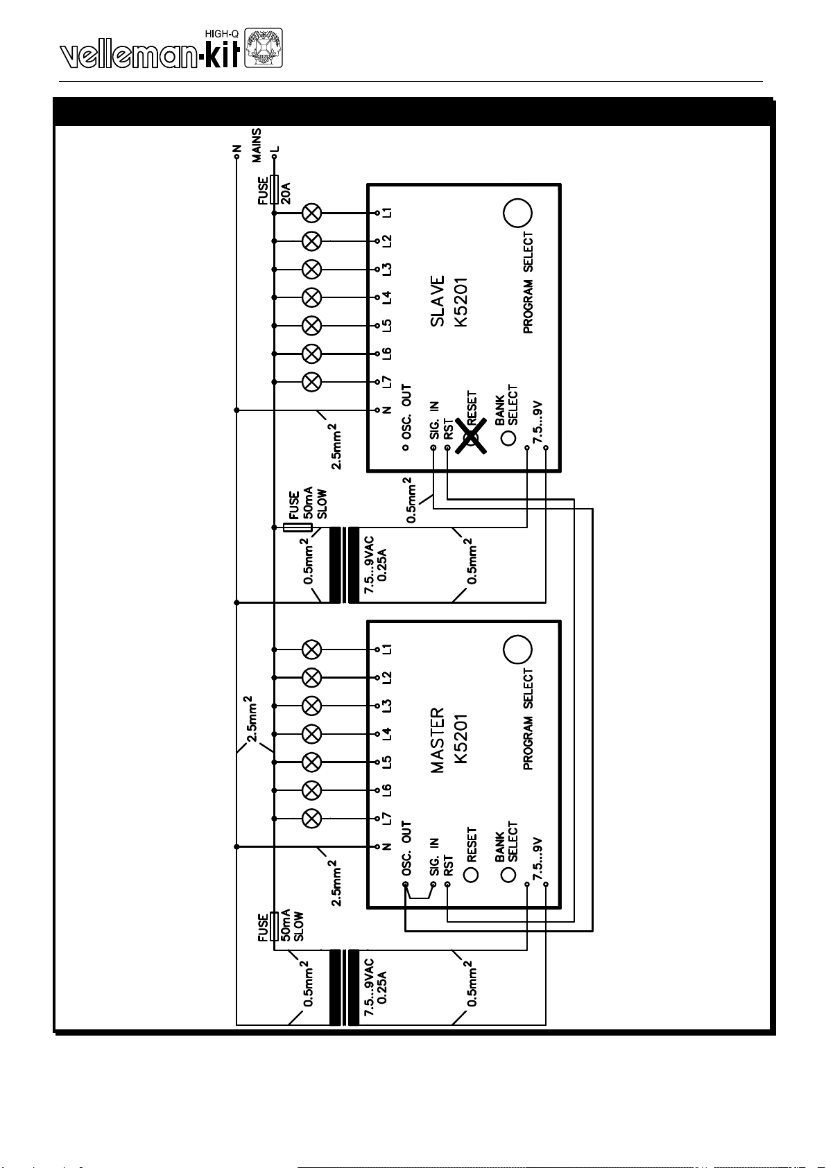
Cascading of two units :
Two units can be hooked-up in cascade configuration, to create a 14 -
channel lightshow. Hook-up both units as shown in the diagram. The ‘RE-
SET’button of the slave unit can be omitted. It is very important that each
unit gets its own power supply transformer. Do not use a single transformer
for both units. Make sure the ‘L’(live) of both kits is connected to the same
phase of the mains. Not doing so will result in damage beyond repair of
both kits, and the risk of fire. Use 4mm² (12AWG) wire for the output sec-
tion and use fuses rated as indicated.
Patterns 15 and 16 have been developed for cascade use. Choose pattern
15 for the master unit, and pattern 16 for the slave unit.
Use :
Choose between 8 different patterns with the rotary switch SW3.
SW2 allows selection of another bank of 8 patterns.
To restart the selected pattern, press ‘RESET’
If internal speed control has been chosen (OSC. OUT connected to SIG.
IN), you can adjust the running speed with RV1.

__________________________________________________________________________________________________________________________________________________________
9
18. CONNECTION EXAMPLE FOR A SINGLE UNIT
PRIM
SEC
...
RESET
BANK SELECT
PROGRAM SELECT
7.5 .. 9VAC
0.25A
FUSE 10A
FUSE 50mA SLOW
MAINS
1.5A/CHANNEL MAX

_______________________________________________________________________________________________________________________________________________________
10
19. CASCADE OPERATION OF TWO UNITS

__________________________________________________________________________________________________________________________________________________________
11
20.DRILL PATTERN
All values are in mm. (1mm = 0.04")

_______________________________________________________________________________________________________________________________________________________
12
21. PCB LAYOUT

__________________________________________________________________________________________________________________________________________________________
13
22. DIAGRAM
Other manuals for K5201
1
Table of contents
Popular Desktop manuals by other brands

Epson
Epson Equity 386SX PLUS Product information guide

American Dynamics
American Dynamics Excalibur SE operating instructions

Emerson
Emerson FB2100 Field Replacement Guide

Pioneer
Pioneer PX-7 Service manual

Avaya
Avaya Sun Fire V880 Installation & maintenance

Dell
Dell GX260 - Optiplex Pentium 4 2.0GHz 512MB 40GB... Service manual