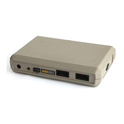
Atari 400 User manual

ATARI®
PERSONAL
COMPUTER
SYSTEM
•
HARDWARE
MANUAL
ATAR
I®
A Warner Communications Company
~

Every
effort
has been
made
to
ensure
that
this
manual
is
an
accurate
document. However, due
to
the
ongoing improvement
and update
of
the
computer software and hardware,
ATARI,
INC.
cannot guarantee
the
accuracy
of
printed
material
after
the
date
of
publication,
nor can
ATARI,
INC.
accept
responsibility
for
errors
or
omissions.

I.
II.
III.
IV.
v.
VI.
TABLE
OF
CONTENTS
INTRODUCTION.
• •• • ••• •• •• • •• •• • •• •• •• •• • ••. • • •
I.
1
DESCRIPTION
OF
HARDWARE
••••••••••••••••••••••
II.1
A.
ANTIC
and
CTIA
•••••••••
••••••••••••••
•••
II.1
B.
POKEY
••••••••••••••••••••••••••••••
•••••
11.23
C.
SERIAL
PORT
•••••••••••••••••••••••••••••
II.25
D.
INTERRUPT
SYSTEM
••••••••••••••••••••••••
II.28
E.
CONTROLLERS
•••••••••••••••••••••••••••••
II.30
HARDWARE
REGISTERS
••••••••••••••••••••••••••
III
.1
A.
PAL••••••••••••••••••••••••••••••••••••III.l
B.
INTERRUPT
CONTROL
••••••••••••••••••••••
III.1
C.
TV
LINE
CONTROL
••••••••••••••••••••••••
III.3
D.
GRAPHICS
CONTROL
••••••••••••••
•••••••••
III.4
E.
PLAYERS
AND
MISSILES
•••••••••••••••••••
III.9
F.
AUDIO
•
•••••••••••••••••••••••••••••••••
I I
I.
12
G.
KEYBOARD
and
SPEAKER
•••••••••••••••••••
III.15
H.
SERIAL
PORT••••••••••••••••••••••••••••III.17
I.
CONTROLLER
PORTS
•••••••••••••••••••••••
III.19
SAMPLE
DISPLAY
PROGRAM
•••••••••••••••••••••••
IV.1
HARDWARE
REGISTER
LISTS
•••••••••••••••••••••••
V.1
A.
ADDRESS
ORDER.
•••••••••••••••••••••••••••V.1
B.
ALPHABETICAL
ORDER
•••••••••••••••••••••••
V.S
FIGURES
•
•••••••••••••••••••••••••••••••••••••
VI.
1
A.
11EMORY
MAP
•
•••••••••••••••••••••••••••••
VI.
1
B.
NTSC
and
PAL
DISPLAY
••••••••••••••••••••
VI.2
C.
SCHEMATICS
•
••••••••••••••••••••••••
••••
•
VI.
3
APPENDIX
A:
APPENDIX
B:
APPENDIX
C
USE
OF
PLAYER/MISSILE
GRAPHICS
WITH
BASIC
MIXING GRAPHICS
MODES
PINOUTS
ii
l·
INTRODUCTION
The
ATARI
(R)
800™
and
ATARI
400™
Personal
Computer
Systems
contain
a 6502
microprocessor,
4
I/O
chips,
operating
system
ROM,
expandable
RAM,
and
several
MSI
chips
for
address
decoding
and
data
bus
buffering.
This
manual
is
primarily
intended
to
describe
the
4
I/O
chips
in
sufficent
detail
to
allow
experienced
programmers
to
create
assembly
language
programs,
such
as
video
games.
All
four
Input/Output
chips
are
controlled
by
the
microprocessor
by
writing
directly
into
their
registers
which
are
decoded
to
exist
in
microprocessor
memory
space
just
as
RAM
does.
These
I/O
chips
can
also
be
interrogated
by
the
microprocessor
by
reading
similar
registers.
Many
registers
are
write
only
and
cannot
be
read
after
they
are
written.
In
some
cases,
reading
from
the
same
address
gives
the
value
contained
in
a
separate
read
only
register.
Some
write
only
registers
are
strobes.
No
data
bits
are
needed
in
this
case
since
the
presence
of
the
address
on
the
bus
is
what
triggers
the
requested
action.
The
usual
convention
is
to
use
the
STA
(Store
Accumulator)
instruction
for
such
registers.
For
example,
STA
WSYNC
performs
the
wait
for
Sync
function.
STX
(Store
X)
or
STY
(Store
Y)
would
work
just
as
well.
In
BASIC, a
POKE
could
be
used
(the
data
could
be
anything).
Reading
a
register
is
accomp-
lished
by
using
any
of
the
load
instructions
(LDA,
LDX
etc.).
In
BASIC
a
PEEK
would
be
used.
When
the
hardware
register
names
are
defined
in
an
equate
list,
the
programmer
can
refer
to
the
registers
by
name
rather
than
using
the
addresses
directly.
It
is
really
not
necessary
for
the
programmer
to
know
which
I/O
functions
are
performed
by
which
of
the
4
chips,
however
it
does
help
in
learning
these
functions.
This
manual
should
be
used
in
conjunction
with
the
Operating
System
(OS)
Manual,
a 6502
programming
manual,
and
the
ATARI
400/800
Basic
Reference
Manual.
CHIP
NAME
ANTIC
CTIA
FUNCTION
DMA(Direct Memory
Access)
control
NMI(Non-Maskable
Interrupt)
control
Vertical
and
Horizontal
fine
scrolling
Light
pen
position
registers
Vertical
line
counter
WSYNC(wait
for
horizontal
sync)
Priority
control
(display
of
overlapping
objects)
Color-Lumimance
control
(colors
and
brightness
assigned
to
all
objects
including
DMA
objects
from
ANTIC
)
PLAYER-MISSILE
objects
(4
players
and 4
missiles)
Graphics
registers
Size
control
Horizontal
position
control
Collision
detection
between
all
objects
Switches
and
triggers
(miscellaneous
I/O
functions)
I.l

CHIP
NAME
POKEY
PIA
FUNCTION
Keyboard
scan
and
control
Serial
communications
port
(bidirecti
mal)
Pot
scan
(digitizes
position
of
8
indepen~~
n
t
pots)
Audio
generation
(4
channels)
Timers
IRQ
(maskable
interrupt)
control
from
peripher?
: s
Random number
generator
Controller
(Joystick)
jacks
read
or
write
Peripheral
control
and
interrupt
lines
IRQ
(maskable)
interrupt
control
from
peripherals
Section
II
describes
the
hardware
in
some
detail,
including
the
various
graphics
modes.
Section
III
lists
the
hardware
registers
one
at
a
time,
describing
what
each
bit
is
used
for.
It
is
organized
by
functional
groups
(interrupts,
graphics,
audio,
etc.).
Section
IV
contains
a
sample
display
program.
Section
V
contains
various
figures
and
block
diagrams
of
the
system.
Sections
VI
and
VII
list
the
hardware
registers
in
address
order
and
alphabetical
order.
Section
VII
includes
hex
and
decimal
addresses,
the
OS
shadow
registers
and
the
page
numbers
where
more
infor-
mation
can
be
found.
1.2

II.
DESCRIPTION
OF
HARDWARE
A.
ANTIC
AND
CTIA
TV
Display:
The
ANTIC
and
CTIA
chips
generate
the
television
display
at
the
rate
of
60
frames
per
second
on
the
NTSC
(US)
system.
The
PAL
(European)
system
is
different
and
is
described
in
the
section
on
NTSC
vs
PAL.
Each
frame
consists
of
262
horizontal
TV
lines
and
each
line
is
made up
of
228
color
clocks,
as
shown
in
figure
VI-3.
The 6502
microprocessor
runs
at
1.79
MHz.
This
rate
was
chosen
so
that
one
machine
cycle
is
equivalent
in
length
to
two
color
clocks.
One
clock
is
approximately
equal
in
width
to
two
TV
lines.
In
any
graphics
mode,
the
display
is
divided
up
into
small
squares
or
rectangles
called
pixels
(picture
elements).
The
highest
resolution
graphics
mode
has
a
pixel
size
of
1/2
color
clock
by
1
TV
line.
A
sample
display
list
is
given
in
section
IV.
The
current
TV
line
may
be
determined
by
reading
the
vertical
counter
(VCOUNT).
This
register
gives
the
line
count
divided
by
2.
There
are
262
lines
per
frame
so
VCOUNT
runs
from 0
to
130 (0
to
155 on
the
PAL
system).
The 0
point
occurs
near
the
end
of
vertical
blank
(see
figure
VI.5).
Vertical
blank
(VBLANK)
is
the
time
during
which
the
electron
beam
returns
back
to
the
top
of
the
screen
in
preparation
for
the
next
frame.
The
Atari
800
does
not
do
interlacing,
so
each
frame
is
identical
unless
the
program
which
is
being
executed
changes
the
display.
Vertical
sync
(VSYNC)
occurs
during
the
fourth
through
sixth
lines
of
vertical
blank
(VCOUNT
•
hex
7D
through
7F).
This
tells
the
TV
set
where
each
frame
starts.
After
VSYNC,
there
are
16 more
lines
of
VBLANK
for
a
total
of
22
lines
of
VBLANK.
The
display
list
jump and
wait
instruction
(to
be
described
later)
causes
the
display
list
graphics
to
start
at
the
end
of
VB
LANK.
Operating
System
(OS): The
ATARI
400/800
comes
with
a
lOK
Operating
System
(OS)
in
ROM.
The
OS
affects
some
of
the
hardware
registers,
so
it
will
be
mentioned
from
time
to
time
in
this
manual.
Refer
to
the
OS
manual
for
more
details.
The
OS
descriptions
in
this
manual
apply
to
the
version
that
was
being
distributed
when
this
manual
was
written.
The
OS
supports
most
of
the
hardware
graphics
modes (BASICS,
GRAPHICS,
PLOT,
and
DRAWTO
commands). The
OS
always
displays
24
background
lines
after
the
end
of
vertical
blank.
This
convention
is
used
at
Atari
to
compensate
for
television
sets
which
overscan.
Most
TV's
are
designed
so
that
the
edges
of
the
picture
are
cut
off.
This
is
fine
for
ordinary
broadcasts,
but
with
a
computer
it
is
essential
for
all
important
information
to
be
displayed
on
the
screen.
It
is
fairly
common
for
four
to
eight
color
clocks
at
the
right
or
left
edge
of
the
picture
to
overscan.
A
TV
set
that
has
excessive
overscan
may
have
to
readjusted
to
obtain
a
satisfactory
display.
II.1

The
OS
uses
192
TV
lines
for
its
display
and
devotes
the
remaining
24
lines
to
overscan.
It
uses
the
standard
display
width
of
160
color
clocks.
The
hardware
will
allow
displays
of
any
length,
but
it
is
recom-
mended
that
the
standards
be
follo~ed.
The
exception
might
be
a
border
or
other
information
which
is
merely
decorative
and
not
essential
to
use
of
the
program.
OS
Shadowing:
Since
many
of
the
hardware
registers
are
write-only
and
cannot
be
read
the
OS
has
a number
of
"shadow
registers"
in
RAM.
Every
TV
frame
during
vertical
blank
the
OS
takes
the
values
in
some
of
its
shadow
registers,
and
writes
them
out
to
the
corresponding
hardware
register.
The
OS
does
attract
color
shifting
on
all
of
the
color
registers
if
ATRACT
(on
OS
register)
is
negative.
This
is
to
prevent
damage
to
the
TV
screen
phosphors
which
can
occur
if
the
brightness
is
turned
up
too
high
and
the
same
high-luminance
display
is
left
on
for
a
long
time.
The
OS
also
reads
the
joysticks
and
other
controllers
during
vertical
blank
and
stores
the
results
in
shadow
registers,
so
that
user
programs
do
not
have
to
include
code
to
unpack
the
data.
There
are
a few
interrupt-related
registers
which
the
OS
changes
or
reads
during
interrupt
processing.
Programs
usually
access
the
OS
shadow
registers
instead
of
accessing
the
hardware
directly.
However,
the
OS
shadowing
can
be
disabled
by
changing
the
vertical
blank
and
interrupt
vectors
(see
OS
manual).
WSYNC:
In
addition
to
a
Vertical
Blank
Interrupt,
which
allows
the
Microprocessor
to
synchronize
to
the
vertical
TV
display,
this
system
also
provides
a
Wait
for
Horizontal
Sync
(WSYNC)
command
that
allows
the
microprocessor
to
synchronize
itself
to
the
TV
horizontal
line
rate.
This
sync
takes
effect
when
the
processor
writes
to
an
I/O
location
called
WSYNC,
whenever
it
desires
horizontal
synchronization.
Writing
to
this
address
sets
a
latch
which
pulls
to
zero
a
pin
on
the
microprocessor
called
READY.
When
READY
goes
to
zero
the
microprocessor
stops
and
waits.
The
latch
is
automatically
reset
(returning
READY
true)
at
the
beginning
of
the
next
horizontal
blank
interval,
releasing
the
microprocessor
to
resume
program
execution.
Object
DMA
(Direct
Memory
Access):
The
primary
function
of
the
Antic
chip
is
to
fetch
data
from
memory
(independent
of
the
microprocessor)
for
display
on
the
TV
screen.
It
does
this
with
a
technique
called
"Direct
Memory
Access"
or
DMA.
It
requests
the
use
of
the
memory
address
and
data
bus
by
sending
a
signal
called
HALT
to
the
microprocessor,
causing
the
processor
to
become "TRI-STATE"
(open
circuit)
all
during
the
next
computer
cycle.
The
ANTIC
chip
then
takes
over
the
address
bus
and
reads
any
data
it
wishes
from
memory.
Another
name
for
this
type
of
DMA
is
"cycle
stealing".
Once
initiated,
this
DMA
is
completely
and
automatically
controlled
by
the
Antic
chip
without
need
for
futher
microprocessor
intervention.
There
are
two
types
of
DMA:
Playfield
and
Player-Missile
(see
Figure
II.2).
The
playfield
DMA
control
circuit
on
the
Antic
chip
resembles
a
small
dumb
microprocessor.
By
halting
the
main
microprocessor
it
can
fetch
its
own
instructions
from
memory
(the
display
list)
addressed
by
its
program
counter(display
list
pointer).
Each
instruction
defines
the
type
(alpha
character
or
memory
map),
and
the
resolution
(size
of
bits
on
the
screen),
and
the
location
of
the
data
in
memory
which
is
to
be
displayed
on
the
next
group
of
lines.
II.
2

In
order
to
begin
this
DMA
the
main
microprocessor
must
store
a
display
list
of
instructions
in
memory,
store
data
to
be
displayed
in
memory,
tell
the
ANTIC
where
the
display
list
is
(initialize
the
display
list
point'er)
and
enable
the
DMA
control
flags
on
the
ANTIC
(DMACTL
register).
In
addition
to
the
playfield
DMA
described
above,
the
ANTIC
chip
simultaneously
controls
another
DMA
channel.
This
type
of
DMA
addresses
PLAYER-MISSILE
graphics
data
stored
in
memory
and
passes
the
graphics
data
on
to
the
CTIA
chip
graphics
registers.
This
type
of
DMA
(if
enabled)
occurs
automatically,
interspersed
with
the
playfield
DMA
described
previously.
This
PLAYER-MISSILE
DMA
has
no
display
list
or
instructions,
and
is
therefore
much
simpler
than
the
PLAYFIELD
DMA.
In
addition
to
the
two
types
of
display
DMA,
the
ANTIC
chip
also
generates
DMA
addresses
for
the
refresh
of
the
dynamic
memory
RAM
used
in
this
system.
This
is
also
completely
automatic
and
need
be
consider-
ed
by
the
programmer
only
if
he
is
concerned
with
real-time
programming
where
an
exact
count
of
the
computer
cycles
is
important.
Color-luminance:
A
color-luminance
register
is
used
on
the
CTIA
chip
for
each
Player-Missile
and
Playfield
type.
Each
color-lum
register
is
loaded
by
the
microprocessor
with
a
code
representing
the
desired
color
and
luminance
of
its
corresponding
Player-Missile
or
Playfield
type.
As
the
serial
data
passes
through
the
CTIA
chip
it
is
"impressed"
with
the
color
and
luminance
values
contained
in
these
registers,
before
being
sent
to
the
TV
display.
In
areas
of
the
screen
where
there
are
no
objects
the
background
color
(COLBK)
is
displayed.
The
CTIA
also
does
collision
detection
(to
be
described
later).
Priority:
When
moving
objects,
such
as
players
and
missiles,
overlap
on
the
TV
screen
(with
each
other
or
with
Playfield)
a
decision
must
be
made
as
to
which
object
shows
in
front
of
the
other.
Objects
which
appear
to
pass
in
front
of
other
·s
are
said
to
have
Priority
over
them.
Priority
is
assigned
to
all
objects
by
the
CTIA
chip
before
the
serial
data
from
each
object
is
combined
with
the
other
objects
and
sent
to
the
TV
screen.
The
priority
of
objects
can
be
controlled
by
the
microprocessor
by
writing
into
the
control
register
PRIOR. The
functions
of
the
bits
in
this
register
are
given
in
the
table
in
the
PRIOR
register
description
in
section
III.
Players
and
Missiles:
The
players
and
missiles
are
small
objects
which
can
be
moved
quickly
in
the
horizontal
direction
by
changing
their
position
registers.
They
are
called
players
and
missiles
because
they
were
originally
designed
to
be
used
in
games
for
objects
such
as
airplanes
and
bullets.
However,
there
are
many
other
possible
applications
for
them.
The
four
player-missile
color
registers,
in
conjunction
with
the
four
playfield
color
registers
and
the
background
color
register,
make
it
possible
to
display
9
different
colors
at
the
same
time.
II.3

MICRO
PROCESSOR
Fi
gure
II.
2
OBJECTS
(no
objects
background)
,..------It
f.....__
_
___,
l
MEMORY
MAP
CHARACTERS
-----
_-
__
,.
"'Player
Missile
DMA
Enable
MEMORY
---
0 B J E C T D I S P L A Y
II.
4
controlled
by
Display
list
instructions
~
:J·f
- - -
-0
(DMACTL)
'
Playfield
DMA
Enable
S 0 U R C E S

There
are
a
total
of
four
players
and
four
missiles.
The
four
missiles
may
be
grouped
together
and
used
as
a
5th
player.
These
objects
are
positioned
horizontally
by
8
horizontal
position
registers
(HPOS
(X)).
These
registers
may
be
reloaded
at
any
time
by
the
proces-
sor,
allowing
an
object
to
be
replicated
many
times
across
a
horizontal
TV
line.
The
shape
of
a
player-missile
is
determined
by
the
data
in
its
graphics
register
(GRAF
(X)).
Players
have
independent
8
bit
graphics
registers.
The
four
missiles
have
2
bit
registers
(located
within
one
address).
These
registers
may
also
be
reloaded
at
any
time
by
the
processor,
although
they
are
usually
changed
during
horizontal
blank
time.
The
data
in
each
graphics
register
is
placed
on
the
display
whenever
the
horizontal
sync
counter
equals
the
corresponding
horizon-
tal
position
register.
The same
data
will
be
displayed
every
line
unless
the
graphic
registers
are
reloaded
with
new
data.
The
player-missile
graphic
registers
may
be
reloaded
by
the
micro-
processor
(GRAF
(X)),
or
automatically
from
memory
with
direct
memory
access
(DMA)
(see
figure
II.3).
The
programmer
must
place
the
object
graphics
in
memory,
write
the
player-missile
base
address
(PMBASE),
and
enable
player-missile
DMA
(DMACTL,
GRACTL).
The
transfer
of
object
graphics
from
memory
to
display
is
then
fully
automatic.
PMBASE
specifies
the
most
significant
byte
(MSB)
of
the
address
of
the
player-missile
graphics.
The
location
of
the
graphics
for
each
object
is
determined
by
adding
an
offset
to
PMBASE
*256
(decimal).
The
bytes
between
the
base
address
and
the
missile
data
are
not
used
by
Antic,
so
they
are
available
to
the
programmer.
Only
the
five
most
significant
bits
of
PMBASE
are
used
with
single-line
resolution
and
the
six
most
significant
bits
are
used
with
two-line
resolution.
This
means
that
the
location
of
the
graphics
in
memory
is
restricted
to
certain
page
boundaries.
Two-line
resolu-
tion
means
that
each
byte
of
data
is
repeated
for
two
lines.
(see
DMACTL,
bit
4).
640
(decimal)
bytes
(5X128)
are
required
for
two-line
resolution
and
1280
bytes
(Sx256)
for
one-line
resolution.
Each
byte
in
the
player
graphics
area
represents
eight
pixels
which
are
to
be
displayed
on
the
corresponding
line(s)
of
the
TV
screen.
A
1
indicates
that
the
player's
color-lum
is
to
be
displayed
in
that
pixel.
The
graphics
may
be
anything,
not
just
rectangles
like
the
ones
in
figure
II.3.
The
player
graphics
may
fill
the
entire
height
of
the
screen
or
they
may
be
only
a
couple
of
lines
high
if
the
rest
of
the
display
data
is
all
O's.
Each
byte
in
the
mis$ile
display
also
r
epresents
eight
pixels,
two
pixels
for
each
missile.
Each
pixel
may
be
1,
2,
or
4
color
clocks,
and
is
determined
by
the
SIZE
registers.
Plavfield:
Playfield
is
always
generated
by
DMA.
There
are
four
playfields,
each
identified
by
its
own
color-lum
register
and
collision
detection.
Playfield
is
generated
by
two
different
DMA
techniques:
memory
map
and
character.
Both
methods
provide
lists
of
instructions
in
memory,
independent
of
the
player-missile
generation.
rr.s

Player-Missile
Base
Address
(PMBASE)
=
MSB
of
address.
Resolution
is
controlled
by
bit
4
of
DMACTL.
ADDRESS
Two-line
resolution
(hex)
+180
+200
+280
+300
+380
+400
OFFSET
One-line
resolution
(hex)
+300
PMBASE*100(hex)
M
+400
----~~
J-.....;;;lL..-....&...--1~
/
PO
+400
P1
+600
P2
+700
P3
+800
Player-Missile
Vertical
screen
map
in
memory
Missile
Number
TV
SCREEN
/
/
/
/
/1
-
POl
I I
I I I
I I I I
...
II
M2
•
I I
MO
-
P2
•
W'
I I
I I
•
1
P1
~
M1
P31
M3
- - -
:--r-1
.;:;..;.....--=~------'
I
I
I
1
Horizontal
position
~~for
each
object
is
set
independently
by
8
horizontal
position
registers.
Each
section
of
memory maps
directly
onto
total
height
of
TV
screen.
Object
vertical
position
is
determined
only
by
its
location
in
its
section
of
memory. One
byte
of
memory
equals
1
or
2
television
lines
vertically.
Figure
II.
2 P L A Y E R - M I S S I L E D M A
II.6

Unlike
players
and
missiles,
there
are
no
horizontal
position
registers
for
playfield.
Each
player
can
only
have
one
byte
of
display
per
line.
Playfield,
on
the
other
hand,
may
require
up
to
48
bytes
per
line
because
it
can
fill
the
entire
width
of
the
screen.
There
are
three
different
playfield
widths:
narrow
(128
color
clocks),
standard
(160
color
clocks),
and
wide
(192
color
clocks).
The
width
is
selected
by
storing
into
DMACTL.
The
advantage
of
a
narrower
width
is
that
less
RAM
is
required
and
fewer
machine
cycles
are
stolen
for
DMA.
The
OS
graphics
modes
use
the
standard
screen
width.
Display
List:
The
display
list
is
a
sequence
of
display
instructions
stored
in
memory.
These
instructions
are
either
one
(1)
byte
or
three
(3)
bytes
long.
The
display
list
can
be
considered
a
display
program,
and
the
Display
List
Counter
that
fetches
these
instructions
can
be
thought
of
as
a
display
program
counter.
(10
bit
counter
plus
6
bit
base
register.)
The
display
list
counter
can
be
initialized
by
writing
to
DLISTH
and
DLISTL.
(or
OS
shadow
registers
SDLSTH
and SDLSTL). Once
initialized
this
counter
value
is
used
to
address
the
display
list,
fetch
the
instruc-
tion,
display
one
(1)
to
sixteen
(16)
lines
of
data
on
the
TV
screen,
increment
the
Display
List
Counter,
fetch
the
next
display
instruction,
and
so
on
automatically
without
microprocessor
control
(see
DLISTL
and
DLISTH).
DLISTL
and
DLISTH
should
be
altered
only
during
vertical
blank
or
when
DMA
is
disabled
(see
DMACTL).
Each
instruction
defines
the
type
(alpha
character
or
memory map) and
the
resolution
(size
of
bits
on
screen)
and
the
location
of
data
in
memory
to
be
displayed
for
a
group
(1
to
16)
of
lines.
Each
group
of
lines
is
called
a
display
block.
THE
DISPLAY
LIST
CANNOT
CROSS
A
1K
BYTE
MEMORY
BOUNDARY
UNLESS
A
JUMP
INSTRUCTION
IS
USED.
\
Counter
DISPLAY
LIST
COUNTER
II.7
/

Display
Instruction
Format:
Each
instruction
consist~
of
ei
t
ner
an
opcode
only,
or
of
an
opcode
followed
by two
(2)
bytes
of
operand.
lopcodel
------Single
Byte
Display
Instruction
lopcodel
!operandi
----Triple
Byte
Display
Instruction
I
operandi
The
opcode
is
always
fetched
first
and
placed
in
the
Instruction
Register.
This
opcode
defines
the
type
of
instruction
(1
or
3
bytes)
and
will
cause
two more
bytes
to
be
fetched
if
needed.
If
fetched,
these
next
two
(2)
bytes
will
be
placed
in
the
Memory
Scan
Counter,
or
in
the
Display
List
Counter
(if
the
instruction
is
a
Jump).
Display
Instruction
Register
(IR):
This
register
is
loaded
with
the
opcode
of
the
current
display
list
instruction.
It
cannot
be
accessed
directly
by
the
programmer.
There
are
three
basic
types
of
display
list
instructions:
blank,
jump,
and
display.
Blank
(
1-byte)
ID7ID6ID5ID41
Ol
Ol Ol
OJ
This
instruction
is
used
to
create
1
to
8
blank
lines
on
the
display
(blackground
color).
Jump
(3-bytes)
D7
D6
-
D4
D3
-DO
1 =
display
list
instruction
interrupt
0-7
=
1-8
blank
lines
0 =
blank
ID7ID61
XI XI
Ol Ol Ol
1!
This
instruction
is
used
to
reload
the
Display
List
Counter.
The
next
two
bytes
specify
the
address
to
be
loaded
(LSB
first).
D7
1
display
list
instruction
interrupt
D6
0 jump
(creates
one
blank
line
on
display)
1 jump and
wait
until
end
of
next
vertical
blank
D5-D4 X
don't
care
D3-DO
1 jump
Display
(1
or
3
bytes)
ID7ID6ID5ID4ID3ID2ID1!DOI
This
instruction
specifies
the
type
of
display
for
the
next
display
block.
D7
1
D6
0
1
DS
1
D4
1
D3-DO
2-F
display
list
instruction
interrupt
1
byte
instruction
3
byte
instruction
(reload
Memory
Scan
Counter
using
address
in
next
two
bytes,
LSB
first).
vertical
scroll
enable
horizontal
scroll
enable
display
mode (memory
or
character
map
-
see
following
pages).
II.8

HSCROL
I lXXI lXXI lXXI lXXI lXXI lXXI lXXI lXXI
Horizontal
Scrolling
VSCROL
I I IXXIXXI I IXXIXXI I IXXIXXI I IXXIXXI
Vertical
Scrolling
LD
MEM
SCAN
I I I I IXXIXXIXXIXXI I I I IXXIXXIXXIXXI
Load
memory
scan
(3
byte)
INST
INTERRUPT I I I I I I I I IXX!XX!XX!XX!XXIXXIXXIXXI
Display
instruction
interrupt
I I I I I I I I I
BLK
1
00
I I
lBO
" 2
10
I I
190
"
3-7
I I I
" B
70
I I IFO
JMP
01 I I
B1
J
VB
41 I I c1
CHR
(40,2,B)
02
12122
32
42152
62
72
B2
92IA2IB2
C2
D2IE2IF2
"
(40,2,10)
03
13123
33
43153
63
73
B3
93IA3IB3
C3
D3IE3IF3
"
(40,4,B)
04
14124
34
44154
64
74
B4
94IA4IB4
C4
D4IE4IF4
"
(40,4,16)
OS
15125
35
45155
65
75
BS
9SIASIBS
cs
DSIESIFS
"
(20,5,B)
06
16126
36
46156
66
76
B6
96IA6IB6
C6
D6IE6IF6
"
(20,5,16)
07
17127
37
47157
67177
B7
97IA7IB7
C7
D7IE7IF7
MAP
(40,4,B)
OB
1BI2B
3B
4BISB
6BI7B
BB
9BIABIBB
CB
DBIEBIFB
"
(B0,2,4)
09
19129
39
49159
69179
B9
99IA9IB9
C9
D9IE9IF9
"
(B0,4,4)
OA
1AI2AI3A
4AISA
6AI-VA
BA
9AIAAIBA
CA
DAIEAIFA
"
(160,2,2)
OB
1BI2BI3B
4BISB
6BI7B
BB
9BIABIBB
CB
DBIEBIFB
"
(160,2,1)
oc
1CI2CI3C
4CISC
6CI7C
BC
9CIACIBC
cc
DCIECIFC
It
(160,4,2)
OD
1DI2DI3D
4DISD
6DI7D
BD
9DIADIBD
CD
DDIEDIFD
It
(160,4,1)
OE
1EI2EI3E
4EI5E
6EI7E
BE
9EIAEIBE
CE
DEIEEIFE
It
(320,2,1)
OFI1FI2FI3F
4FI5F
6FI7F
BF
9FIAFIBF
CF
DFIEFIFFI
I I I
I I
_._I
__
I
I
Number
of
TV
lines
per
cell
Number
of
Colors
(Background
+
Playfield
types)
Number
of
Horizontal
cells
(standard
width
screen)
Figure
II.3
DISPLAY INSTRUCTION
OPCODES
II.9
Blank
1
line
Blank
2
lines
Blank
3
thru
7
lines
Blank
B
lines
Jump
(3
byte
instruction)
Jump
&
wait
for
Vert.
Blank
(also
3
byte)
Character
Mode
Instructions
Memory
Map Mode
Instructions

Bit
7
of
a
display
list
instruction
can
be
set
to
create
a
display
list
interrupt
if
bit
7
of
NMIEN
is
set.
The
display
list
interrupt
code
can
change
the
colors
or
graphics
during
the
middle
of
the
TV
disnlay.
The
type
of
interrupt
is
determined
by
checking
NMTST.
NMIRES
clears
NMIST.
The
current
OS
will
vector
through
VDSLST
(Hex 200 and 201)
to
the
user's
display
list
interrupt
routine.
See
the
JS
manual
for
program-
ming
details.
Bits
5
and
4
of
a
display
type
of
display
list
instruc\
.
on~
~
re
used
to
enable
vertical
and
horizontal
scrolling.
The
amou11t
of
scrolling
depends
on
the
values
in
the
VSCROL
and
HSCROL
registers
(to
be
described
later).
Memory
Scan
Counter:
This
counter
is
not
directly
accessible
by
the
programmer.
It
is
loaded
with
the
value
in
the
last
2
bytes
of
a 3
byte
(non-Jump)
instruction.
This
counter
points
to
the
location
(address)
in
memory
of
data
to
be
directly
displayed
(memory
map
display)
or
to
the
location
of
character
name
strings
to
be
indirectly
displayed
(character
display).
A
single
byte
instruction
does
not
reload
this
counter.
This
implies
a
continuation
in
memory
of
data
to
be
displayed
from
that
displayed
by
the
previous
instruction.
Since
this
counter
really
consists
of
4
bits
of
register
and 12
of
actual
counter,
a
continuous
memory
block
cannot
cross
~
4K
byte
memory
boundaries,
unless
the
counter
is
repositioned
with
a 3
byte
Load Memory
Scan
Counter
instruction.
MSB
third
byte
of
3
byte
byte
instruction
7 6 5 4 3 2 1
\
0 7
Counter
LSB
Second
byte
of
3
byte
instruction
6 5 4 3 2
/
1 0
Memory
Map
Display
Instructions:
Data
in
memory
(addressed
by
the
Memory
Scan
Counter)
is
displayed
directly
when
executing
a memory
(bit)
map
display
instruction.
As
data
is
being
displayed
it
is
also
stored
in
a
shift
register
so
that
it
can
be
redisplayed
for
as
many
TV
lines
as
required
by
the
instruction.
rr.10

Memory
Scan
Counter
Addresses
each
byte
One
line
worth
of
memory
is
loaded
into
the
shift
register
Memory
Shift
register
data
is
displayed
for
four
TV
scan
lines
in
this
example.
In
Instruction
Register
(IR)
display
modes 8
through
F,
one
or
two
bits
of
memory
are
used
to
specify
what
is
to
be
displayed
on
each
pixel
of
the
screen.
Pixel
sizes
range
from
1/2
clock
by
1
TV
line
to
4
clocks
by
8
TV
lines.
The
OS
and
BASIC
support
most
of
these
graphics
modes
(BASIC
GRAPHICS
command).
Two
modes,
C
and
E,
are
not
supported
by
the
OS.
These
modes
have
rectangular
pixels,
which
are
approximately
twice
as
wide
as
they
are
high.
In
IR
mode
F,
only
one
color
(COLPF2)
can
be
displayed.
Two
different
luminances
are
available.
If
a
bit
is
a
zero,
then
the
luminance
of
the
corresponding
pixel
comes
from
COLPF2.
If
the
bit
is
a
one,
them
the
luminanc
e
is
determined
by
the
contents
of
COLPFl
(abbreviated
to
PF1).
In
IR modes
9,B,
and
C, two
different
colors
can
be
displayed.
A
zero
indicates
background
color
and
a
one
indicates
PFO
color.
The
difference
between
the
various
modes
is
in
the
size
of
the
pixels.
In
IR modes
8,A,D,
and
E,
two
bits
are
used
to
specify
the
color
of
each
pixel.
This
allows
four
different
colors
to
be
displayed.
However,
only
four
pixels
can
be
packed
into
each
byte,
instead
of
eight
as
in
the
previous
modes.
The
bit
assignments
are
shown
below.
SHIFT
REGISTER
7
6[5
4
[3
2 1 0
II.ll
1 6 I5 4 3 2 I1 o
2
bits
form
one
pixel

Memory
MaE
DisElay
Modes
I
OS
I
!Colors
IPixelsiBytesiScan
!Color
I I
Bit
I I
I and
IInst.l
per
I
per
I
per
ILinesiClocksiBits
!Values
I
Color
I
I
BASIC
IReg.
Mode
I
Std.
!Std.
I
per
I
per
I
per
I
in
I Reg. I
Modes!HEX
I
Line
I
Line!Pixel!Pixel
IPixeljPixel
!S
el
ect!
I I I I I I I
oo
I
BAK
3 I 8 4 I
40
I 10 I 8 I 4 I 2 I
01
PFO
I I I I I I I
10
PFl
I I I I I I I 11
PF2
I I I I I I I
4 I 9 2 I
80
I 10 I 4 I 2 I 1 I 0
BAK
I I I I I I I 1
PFO
I I I
BAK
5 I A I 4
80
20 4 2 2 I
PFO
I I I
PF1
I I I
PF2
I I I
6 I B I 2 160
20
2 1 1 I 0
BAK
I I I 1
PFO
2 160 20 1 1 1 0
BAK
1
PFO
I I
BAK
7 I D 4 160
40
2 1 2 I
01
PFO
I I
10
PF1
I I
11
PF2
I I 00
BAK
-I E 4 160
40
1 1 2 I
01
PFO
I I
10
PF1
I 11
PF2
I
8 1
!z
320
40
1
!z
1 I 0
PF2
I 1
PF1
I
{LUM)
11.12

Character
Display
Instructions:
The
first
step
in
using
the
character
map
mode
is
to
create
a
character
set
in
memory
(or
the
built-in
OS
character
set
at
hex
EOOO
may
be
used).
The
character
set
contains
eight
bytes
of
data
for
the
graphics
for
each
character.
The
meaning
of
the
data
depends
on
the
mode. The
character
set
can
contain
64
or
128
characters,
also
depending
on
the
mode. The
MSB
(Most
Significant
Byte)
of
the
address
of
the
character
set
is
stored
in
CHBASE
(or
the
OS
Shadow
CHBAS).
Only
the
most
significant
six
or
seven
bits
of
CHBAS
are
used
(see
CHBASE
description
in
section
III).
The
other
one
or
two
bits
and
the
LSB
of
the
address
are
assumed
to
be
zero,
so
the
character
set
must
start
at
an
acceptable
page
boundary.
The
next
step
is
to
set
up
the
display
list
for
the
desired
mode.
Then
the
actual
display
is
set
up.
This
consists
of
a
string
of
character
names
or
codes.
Each
name
takes
one
byte.
The
last
6
or
7
bits
of
the
name
selects
a
character.
For
a 64
character
set,
the
name
would
range
from
0
through
63
(decimal).
For
a 128
character
set,
the
range
would
be
0
through
127
(decimal).
The
upper
one
or
two
bits
of
the
name
byte
are
used
to
specify
the
color
or
other
special
information,
depending
on
the
mode.
Character
names
(codes)
are
fetched
by
the
memory
scan
counter,
and
are
placed
in
a
shift
register.
On
any
given
line
of
display
the
shift
register
rotates,
changing
only
the
name
portion
of
the
character
address,
as
shown
below.
After
a
full
line
of
character
data
has
been
displayed
the
line
counter
will
increment.
The
next
line
again
addresses
all
characters
by
name
for
that
line
number.
In
20
character
per
line
modes
the
seven
most
significant
bits
of
CHBASE
are
used.
This
requires
that
the
character
set
to
start
upon
a 512
byte
memory
boundary.
The
set
must
contain
64
charcters,
8
bytes
each,
giving
a
total
of
512
bytes
for
the
set.
The 40
character
per
line
modes
use
the
six
most
significant
bits
of
CHBASE,forcing
the
character
set
to
start
on a
1K
byte
memory
boundary.
The
set
must
have
128
characters
of
8
bytes
each.
This
gives
a
total
of
1024
bytes
for
the
set.
Hex
Graphics
Chars.
Number
Bytes
Number
Bytes
Code
Mode
Per
of
per
of
Char.
in
Line
Colors
Char.
in
set
Char
Set
2 0 40 2 8 128 1024
I
3 40 2 8 128 1024
4 40 4 8 128 1024
5 40 4 8 128 1024
6 1 20 5 8 64 512
7 2 20 5 8 64 512
II.13

Shift
Register
CHBASE
l I
I
r
I
Character
Display
(20
Character
per
line
mode
example)
Codes
(names)
Stored
in
Shift
Register
F
Color
Register
Select
I
not
.............
v
I
X
I
__
:;_____..
I
Address
portion
of
Character
name
used
..,.....,
v
I
Character
Data
Address
Character
Set
in
Memory
w
y
Addresses
data
in
character
set
displays
on
the
Color
assigned
by
color
register
selected
II
.14
z
'\
I
Internal
codes
for
characters
in
memory
F
X
z
0
1 TV
2
Scan
3
Lines
4
5
6
7
/

There
are
six
charcter
map
modes,
IR modes 2
through
7.
Modes
2,6
and 7
are
supported
by
the
OS
and
BASIC
(GRAPHICS
0,1
and
2).
In
IR modes 6
and
7,
the
upper
two
bits
of
each
character
name
select
one
of
four
playfield
colors.
For
each
data
bit
that
contains
a
one,
the
selected
playfield
color
is
displayed.
For
each
zero
data
bit,
the
background
color
is
displayed.
The
four
character
colors
plus
the
background
color
gives
a
total
of
five
different
colors.
the
mode 6
characters
are
eight
lines
high
and
the
mode 7
characters
are
sixteen
lines
high
(each
data
byte
is
displayed
for
two
lines).
In
IR
modes 4
and
5,
each
character
is
only
four
pixels
wide
instead
of
eight
(as
in
the
other
modes).
Two
bits
per
pixel
of
data
are
used
to
select
one
of
three
playfield
colors,
or
background.
Seven~
bits
are
used
to
select
the
character.
If
the
most
significant
name
bit
is
a
zero
then
data
of
10
(binary)
selects
PF1.
If
the
name
bit
7
is
one,
then
data
bits
of
10
select
PF2.
This
makes
it
possible
to
display
two
characters
with
different
colors,
using
the
same
data
but
different
name
bytes.
In
IR modes 2
and
3,
each
pixel
is
half
of
a
color
clock
in
width.
This
makes
it
possible
to
have
forty
eight-pixel-wide
characters
in
a
standard
width
line.
These
modes
are
similar
to
memory mode F
in
that
two
luminances
can
be
displayed,
but
only
one
color
is
available
at
a
time.
In
IR
mode
3,
each
character
is
10
lines
high.
This
makes
it
possible
to
define
lower
case
characters
with
descenders.
The
last
fourth
of
the
character
set
(name
bits
5
and
6
equal
to
one)
is
lowered.
The
hardware
takes
the
first
two
data
bytes
and
moves
them
to
the
bottom
of
the
character,
displaying
two
blank
lines
at
the
top
of
the
character
(see
next
page).
In
IR modes 2
and
3,
bit
7
of
the
character
name
is
used
for
inverse
video
or
blanking.
This
is
controlled
by
CHACTL
(Character
Control).
If
bit
2
of
CHACTL
is
a
one
then
all
of
the
characters
will
be
displayed
upside
down,
regardless
of
mode.
If
CHACTL
bit
1
is
set,
then
each
character
which
has
bit
7
of
its
name
set
will
be
displayed
in
inverse
video
(the
luminances
will
be
reversed).
If
CHACTL
bit
0
is
set,
then
each
character
which
has
bit
7
set
will
be
blanked
(only
background
wil
be
displayed)
.
Characters
can
be
blinked
on and
off
by
setting
name
bit
7
to
1
and
toggling
CHACTL
bit
0.
Inverse
video
and
blank
apply
only
to
IR
modes 2
and
3.
If
both
inverse
video
and
blank
are
set
then
the
character
will
appear
as
an
inverse
video
blank
character
(solid
square).
Hardware
Collision
Detection:
60
bits
of
collision
register
are
provided
to
detect
and
store
overlap
(hits)
between
players,
missiles
and
playfield.
These
collisions
can
be
read
by
the
microprocessor
from
addresses
DOOO
through
DOOF.
There
are
no
bits
for
missile
to
missile
collisions.
16
bits
for
Missile
to
Playfield
16
bits
for
Player
to
Playfield
16
bits
for
Missile
to
Player
12
bits
for
Player
to
Player
(PO
to
PO
always
reads
as
zero,
etc.)
The
1/2
clock
memory
map
mode
(IR
code
1111)
and
the
1/2
clock
Character
mode
(IR
codes
0011
and
0010)
are
both
playfield
type
2
collisions
and
will
be
stored
irr
bit
2
of
the
playfield
collision
registers.
II.15
Other manuals for 400
14
This manual suits for next models
1
Table of contents
Other Atari Desktop manuals

Atari
Atari 1200 XL Quick start guide

Atari
Atari 600XL Instruction manual

Atari
Atari 400 User manual

Atari
Atari ST User manual

Atari
Atari 600XL User manual

Atari
Atari PC User manual

Atari
Atari 600XL Instruction manual

Atari
Atari 520STE Quick start guide

Atari
Atari TT030 User manual

Atari
Atari ST Use and care manual