Velleman K8077 User manual

Total solder points: 383
Difficulty level: beginner 1 2 3 4 5 ⌧advanced
100W SUBWOOFER KIT
ILLUSTRATED ASSEMBLY MANUAL H8077IP-1
Powerful bassfromasmallcabinetthanksto
thedualspeakerprinciple
K8077
K8077

2
Features & specifications
Features :
bass-reflex system with adjustable tube
compact size due to dual-speaker principle
adjustable level and filter response
auto power-on/off system
phase switch (0°-180°)
line level and speaker level inputs for maximum compatibility
'Full-range'-option for use in active speaker system
separate chamber for electronics avoids air leaks
Specifications
• power output: 100Wrms/ 4ohm (10% THD)
• filter freq. response:
wide: 25 - 110Hz (-6dB)
narrow: 18 - 65Hz (-6dB)
• speakers: two 6.5" 8 ohm drivers
• line level input sensitivity: 500mV
• auto turn-on level: 5mV
• volume*: approx. 20 liter
• power supply: 120/230VAC
• dimensions*: 460x310x210mm / 18,22 x 12,28 x 8,32"
(*) recommended enclosure. Drawings for enclosure are included

3
Assembly hints
1. Assembly (Skipping this can lead to troubles ! )
Ok, so we have your attention. These hints will help you to make this project
successful. Read them carefully.
1.1 Make sure you have the right tools:
• A good quality soldering iron (25-40W) with a
small tip.
• Wipe it often on a wet sponge or cloth, to keep it clean; then apply solder to
the tip, to give it a wet look. This is called ‘thinning’ and will protect
the tip, and enables you to make good connections. When solder
rolls off the tip, it needs cleaning.
• Thin raisin-core solder. Do not use any flux or grease.
• A diagonal cutter to trim excess wires. To avoid injury when cutting
excess leads, hold the lead so they cannot fly towards the eyes.
• Needle nose pliers, for bending leads, or to hold compo-
nents in place.
• Small blade and Phillips screwdrivers. A basic range
is fine.
For some projects, a basic multi-meter is required, or might
be handy
1.2 Assembly Hints :
⇒Make sure the skill level matches your experience, to avoid disappointments.
⇒Follow the instructions carefully. Read and understand the entire step before
you perform each operation.
⇒Perform the assembly in the correct order as stated in this manual
⇒Position all parts on the PCB (Printed Circuit Board) as shown on the draw-
ings.
⇒Values on the circuit diagram are subject to changes.
⇒Values in this assembly guide are correct*
0.000

4
⇒Use the check-boxes to mark your progress.
⇒Please read the included information on safety and customer service
* Typographical inaccuracies excluded. Always look for possible last minute
manual updates, indicated as ‘NOTE’ on a separate leaflet.
1.3 Soldering Hints :
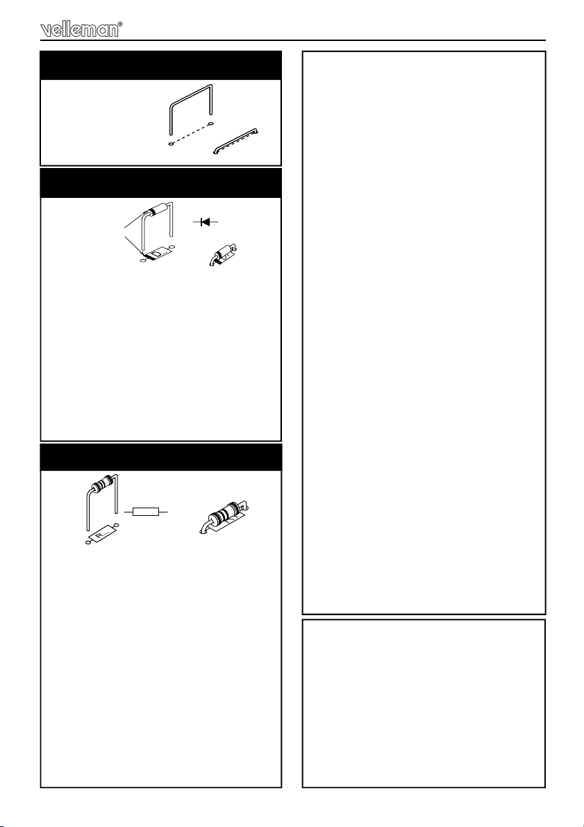
1- Mount the component against the PCB sur-
face and carefully solder the leads
2- Make sure the solder joints are cone-shaped
and shiny
3- Trim excess leads as close as possible to the
solder joint
REMOVE THEM FROM THE TAPE ONE AT
A TIME !
Assembly hints
AXIAL COMPONENTS ARE TAPED IN
THE CORRECT MOUNTING SEQUENCE !
5
Construction
R1 : 22K (2 - 2 - 3 - B)
R2 : 22K (2 - 2 - 3 - B)
R7 : 47K (4 - 7 - 3 - B)
R12 : 22K (2 - 2 - 3 - B)
R13 : 22K (2 - 2 - 3 - B)
R14 : 33K (3 - 3 - 3 - B)
R15 : 22K (2 - 2 - 3 - B)
R16 : 10K (1 - 0 - 3 - B)
R17 : 22K (2 - 2 - 3 - B)
R18 : 1K (1 - 0 - 2 - B)
R19 : 10K (1 - 0 - 3 - B)
R20 : 1K (1 - 0 - 2 - B)
R21 : 1M (1 - 0 - 5 - B)
R22 : 33K (3 - 3 - 3 - B)
3. 1/4W resistors.
R...
J1 … J8
R3
R4
R8
R11
1. Jump wires.
D1 : BAT85
D2 : 1N4148
D3 : 1N4148
D4 : 1N4148
D5 : 1N4007
D6 : 1N4007
D7 : 1N4007
D8 : 1N4007
D9 : 1N4007
D10 : 1N4007
2. Diodes (check the polarity)
CATHODE
D...
R23 : 1K (1 - 0 - 2 - B) *
R24 : 100K (1 - 0 - 4 - B)
R25 : 390K (3 - 9 - 4 - B)
R26 : 15K (1 - 5 - 3 - B)
R27 : 470 (4 - 7 - 1 - B)
R28 : 15K (1 - 5 - 3 - B)
R29 : 100K (1 - 0 - 4 - B)
R30 : 100K (1 - 0 - 4 - B)
R34 : 10K (1 - 0 - 3 - B)
R35 : 10K (1 - 0 - 3 - B)
R36 : 10K (1 - 0 - 3 - B)
R37 : 10K (1 - 0 - 3 - B)
R39 : 10K (1 - 0 - 3 - B)
R40 : 100K (1 - 0 - 4 - B)
R41 : 33K (3 - 3 - 3 - B)
R42 : 100 (1 - 0 - 1 - B)
R43 : 47K (4 - 7 - 3 - B)
R44 : 330 (3 - 3 - 1 - B)
R45 : 220 (2 - 2 - 1 - B)
R46 : 47 (4 - 7 - 0 - B)
R47 : 3K3 (3 - 3 - 2 - B)
R48 : 680 (6 - 8 - 1 - B)
R49 : 3K3 (3 - 3 - 2 - B)
R50 : 3K3 (3 - 3 - 2 - B)
R51 : 10 (1 - 0 - 0 - B)
R52 : 3K3 (3 - 3 - 2 - B)
R53 : 1K5 (1 - 5 - 2 - B)
R54 : 3K3 (3 - 3 - 2 - B)
R55 : 680 (6 - 8 - 1 - B)
R56 : 1K (1 - 0 - 2 - B)
R57 : 220 (2 - 2 - 1 - B)
R58 : 47 (4 - 7 - 0 - B)
R61 : 1K8 (1 - 8 - 2 - B)*
R62 : 470 (4 - 7 - 1 - B)
(*) Select operation mode :
Subwoofer:
R61 : not mounted
R23 : 1K
Full range:
R61 : 1K8
R23 : not mounted
Full range with 6dB bass boost:
R61 : 1K8
R23 : 1K

6
R5 : 100 (1 - 0 - 1 - B - 9)
R6 : 470 (4 - 7 - 1 - B - 9)
R9 : 100 (1 - 0 - 1 - B - 9)
R10 : 470 (4 - 7 - 1 - B - 9)
R31 : 820 (8 - 2 - 1 - B)
R32 : 820 (8 - 2 - 1 - B)
R33 : 560 (5 - 6 - 1 - B)
R38 : 2K7 (2 - 7 - 2 - B - 9)
Construction
ZD1 : 5V1
ZD2 : 5V1
ZD3 : 15V0
ZD4 : 15V0
ZD5 : 9V1
5. Zener diodes (check the polarity)
CATHODE
ZD...
IC1 : 8p
IC2 : 14p
IC3 : 8p
8. IC sockets. Watch the position
of the notch!
C1 : 390pF (391)
C2 : 390pF (391)
C3 : 100nF (104)
C4 : 100nF (104)
C5 : 100nF (104)
C6 : 100nF (104)
C7 : 100nF (104)
C8 : 100nF (104)
C9 : 100nF (104)
C10 : 100nF (104)
C11 : 680pF (680)
C12 : 680pF (680)
C13 : 47nF (473)
C14 : 47pF (47)
C15 : 47pF (47)
C16 : 47pF (47)
C17 : 1nF (102)
C18 : 100pF (101)
C19 : 10nF (103)
9. Capacitors
c...
LD3 : RED (-35/+35VDC)
7. LEDs. Watch the polarity!
LD1
CATHODE
4. Metallfilm resistors.
R...
T7 : 5 pins
T8 : 6 pins
T9 : 6 pins
6. Pinheaders

7
Construction
D11 : 1N5404
D12 : 1N5404
D13 : 1N5404
D14 : 1N5404
10. Diodes (check the polarity)
CATHODE
C20 : 0,047µF / 63V
C21 : 0,068µF / 63V
C22 : 4700pF/ 100V
C23 : 0,022µF / 63V
C24 : 0,022µF / 63V
RV3 : 1K
Turn RV3 fully
counter-
clockwise
11. Trim potentiometer
R4
T1 : BC547B
T2 : BC547B
T3 : BC640
T4 : BC640
T5 : BC557
T6 : BC639
12. Transistors
T1
R59 : 0,47
R60 : 0,47
13. 5W resistors
R...
2mm
SK12 : GND
14. PCB tab
LS+
LS-
AC BLUE
AC RED
AC GREY
AC YELLOW
15. Flat receptacles
SK...
SK11
Remark: if you wish to have a
‘POWER’ and ‘ON’ indication in a
remote location, you can remove the
shunts and connect the supplied fe-
male board to wire connector and two
extra LED’s
16. Male board wire connector
SK11
SK11
-
-
+
+
+
-
+
-
SK11 +
-
+
-
D...
Wiring diagram:
Brown cathode1 ON
Red anode1
Orange anode2
Yellow cathode2
POWER
SK11 +
-
+
-
Cathode2
Cathode1
Anode1
Brown
Red
Orange
Yellow
Anode2
8
C25 … C28 : 10µF / 35V
C29 : 22µF / 50V
C30 … C35 : 100µF / 50V
C36 : 470µF / 16V
construction
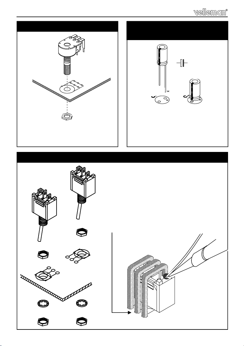
RV1 : Stereo log. 50K
RV2 : Stereo log. 50K
17. Potentiometers 18. Electrolytic capacitors.
Watch the polarity !
C...
SW1 : Phase
SW2 : Mode
Position the switches onto the PCB first.
Mount a wire jumper onto each switch
connector and connect these with the switch
connector on the PCB.
19. Switches
Fig 1.0
Fig 1.0
COMPONENT SIDE
COMPONENTSIDE

9
RY1 : VR5V242C
( 24VDC - 5A - 2C)
20. Relais
Construction
C37 : 3300µF / 50V
C38 : 3300µF / 50V
21. Electrolytic capacitors.
Watch the polarity !
C...
MOUNT THEM ON THE
SOLDERSIDE !
Mount first :
SK1 : LOW LEVEL IN 'RIGHT'
SK3 : HIGH LEVEL IN 'RIGHT'
Mount now :
SK2 : LOW LEVEL IN 'LEFT'
SK4 : HIGH LEVEL IN 'LEFT'
22. Female cinch connectors
SK...
SOLDERSIDE
SK...
LD1 : POWER (red)
LD2: ON (red)
Mount both LEDs on the solderside
at 8mm of the PCB cathode is
marked with 'C'.
23. LEDs
8mm
COMPONENT SIDE
SOLDERSIDE
Inspect the complete assembly.
Once the PCB is mounted on the
heatsink, the solderside is no
longer accessible.
Cathode Anode

10
Fixing the knobs
Slide the knobs fully onto the potentiometer axes.
Turn potentiometers fully counterclockwise
24. Fixing the knobs
!
Watch the position of
the dot !

11
25. Fixing the PCB onto the heatsink
M3 nut
Spacer
M3 bolt 16mm
Fixing the PCB
Fixing the PCB onto the heatsink :
(1) Slide 2 x 5mm plastic spacers over the black bolts.
(2) Carefully position the PCB onto the two bolts
(3) fasten using two nuts.

12
Tighten gently, making sure that :
• the leds protrude the holes
• the cinch (RCA) connectors do not touch the heatsink
• the knobs do not touch the heatsink
• the switches do not touch the heatsink
(4) fit the remaining bolts and spacers
(5) fit the nuts and tighten them all, while minding the position of the knobs,
switches, leds and connectors
5X
Fixing the PCB

13
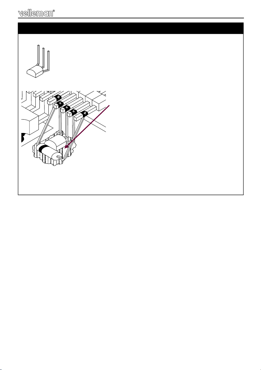
26. Fixing the power transistors T8 (TIP147) & T9 (TIP142)
Fixing power transistors
bend both transistors as indicated.
• apply a drop of heat conductive compound on the heatsink.
• position the mica onto the heatsink so that the hole coincide with the hole in
the heatsink, press gently.
• apply a drop of heat conductive compound on the mica.
• Mount the transistor on the heatsink, using a 16mm bolt, lock washer and nut.
Make sure the transistor leads are correctly positioned
between the pins of the pinheader.
• Tighten gently.
+/-5mm
Heat conductive
compound
Lock washer
M3 nut
M3 bolt
mica
T8 (TIP147)

14
• Solder the transistor leads
Repeat for the remaining transistor T9 (TIP142)
Fixing Diode D15
Bend the leads as indicated.
Put a large drop of heat conductive
compound on the heatsink.
Solder the diode to the two outer pins of
the pin header.
Make sure that the diode is bend to-
wards the heat conductive com-
pound.
Mind the direction of the ring. It should
face transistor T9
27. Fitting diode D15 (1N4007)
!
15
Fitting transistor T7
Bend the leads as indicated.
Put a large drop of heat conductive compound
on the heatsink.
Solder the transistor to the remaining pins of
the pinheader.
The flat side of the transistor must face the
heatsink.
Make sure that the transistor and diode leads do not touch each other
and make sure that the diode does not touch the power transistor.
28. Fitting transistor T7 (BC547)
16
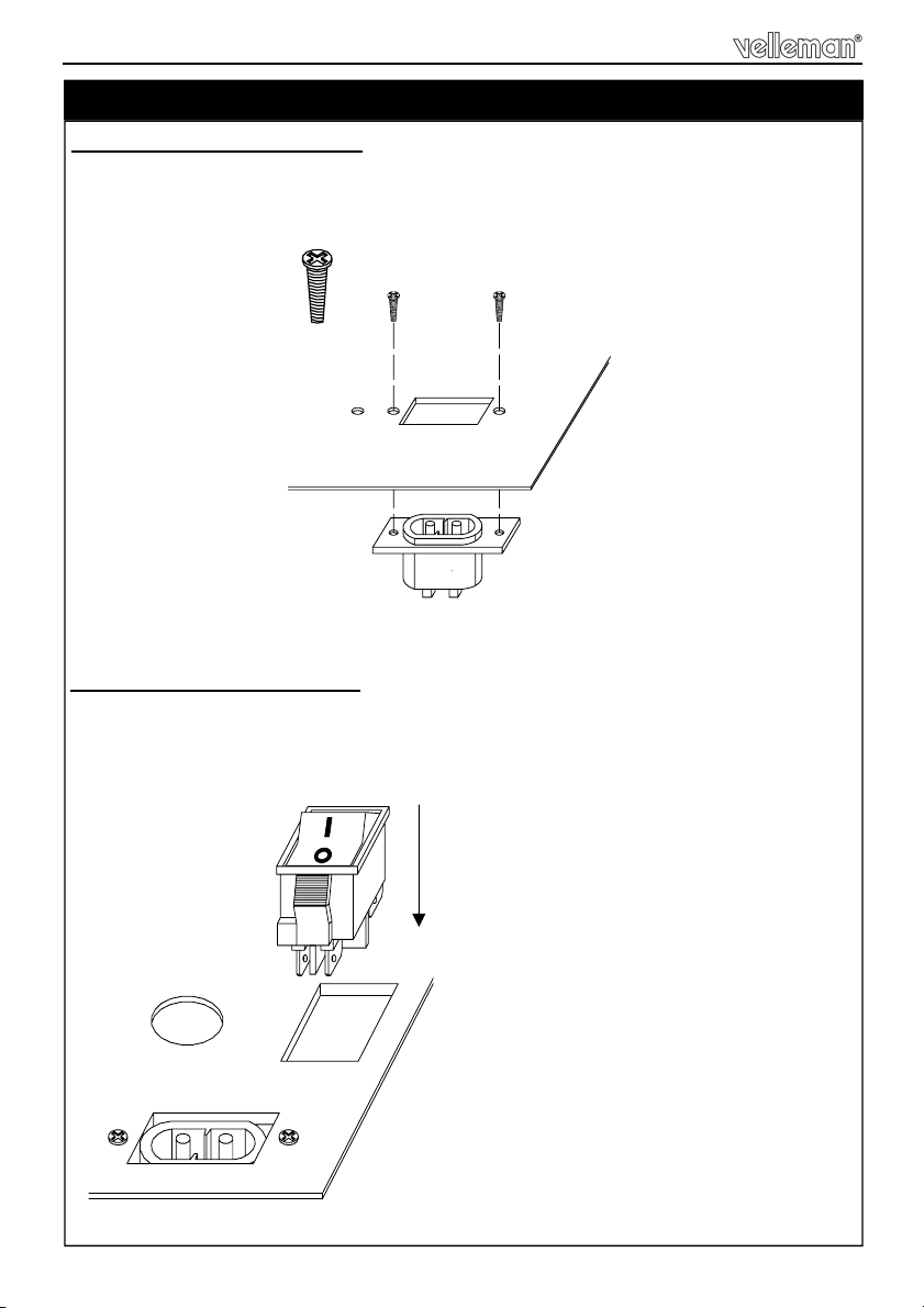
2. Mounting the power switch
Click the power switch onto the heatsink. Make sure the '0'-position of the switch
faces the AC connector.
Mounting power supply section
29. Mounting the power supply section
10mm screw
1. Mounting the AC connector
Position the AC connector at the PCB side of the heatsink and fix by means of
two 10mm black screws.

17
2A T
3. Mounting the fuse holder
Place the fuse holder and fix with the included nut.
Place a 2A T fuse.
Mounting power supply section
If necessary , enlarge mounting hole

18
4. Fixing the transformer
Rotate the transformer in such a way that the red/yellow/blue/grey wires point
towards the PCB.
Tighten the nut
Mounting power supply section
bolt
washer
transformer
washer
disk
nut

19
5. Wiring the ground connection
Connect one end of the cable to the red ring terminal.
Connect the ring terminal to the chassis
by means of a black bolt, spring washer
and nut.
Solder the other end to the PCB tab
(SK12)
Mounting power supply section
1 2
M3 nut
spring washer
16mm M3 bolt
Scratch off anodizing
for better conduction

20
6. Transformer wiring (red/yellow/blue/grey wires)
Slide an insulation sleeve over each wire.
Solder a connector to each wire
Slide the sleeve over the connector
• Connect the wires to the PCB. Mind the colours!
• Group the wires by means of two cable ties
• Cut the largest of the two heatshrink tubes into 3 pieces: 3cm - 3cm - 4cm
SOLDER
REMARK : In case you trim the wires, always
remove the insulating lacquer (+/- 1cm)
Mounting power supply section
GREY
RED
BLUE YELLOW
3cm 3cm 4cm
Other manuals for K8077
1
Table of contents
Other Velleman Subwoofer manuals


Popular Subwoofer manuals by other brands


Klipsch
Klipsch Reference Series RW-12d Specifications

JL Audio
JL Audio Stealthbox SB-S-LWAG/10W6v2/DG installation guide

Ground Zero
Ground Zero TITANIUM Series owner's manual

Ground Zero
Ground Zero RADIOACTIVE Series owner's manual

Axiom Audio
Axiom Audio EP125 owner's manual

L-Acoustics
L-Acoustics KIVA SB18i Rigging manual