EP125/EP175/EP350 Amplier
Troubleshooting pages:
www.axiomaudio.com
Step 9:
GROUND LOOP:
e Chassis ground screw
should be removed when using
the XLR input.
If your subwoofer is producing
a 60 Hz hum, remove the
Chassis Ground Screw. If
this does not solve the 60 Hz
hum, call 1-866-244-8796 or
consult the troubleshooting
page at www.axiomaudio.com/
troubleshooting_ep175.html
POWER INDICATOR: e
LED Power indicator glows
Green when it’s on.
Please Note: e EP125 v2,
EP175 v2 or EP 350 v2 will
shut down if heavily over
driven into distortion. To
reset, turn the power switch
OFF then ON.
NEED HELP
TROUBLESHOOTING?
Please feel free to contact us
at 1-866-244-8796 or
www.axiomaudio.com
for more information.
Step 1:
BALANCED XLR LINE IN: If the A/V receiver or A/V
preamp-processor has balanced XLR subwoofer line-out
connections, you may connect a Balanced XLR male
connector to the XLR female input. First remove the 1/4”
phone-to-RCA adaptor from the XLR input jack.
RCA LINE IN: Your subwoofer is shipped with a supplied
1/4” Phone-to-RCA-jack adapter already installed in the
XLR female input. Connect a shielded coaxial cable, with
male RCA plugs on each end, from the A/V receiver or
A/V preamp processor’s Subwoofer Output jack to the
RCA female jack on the 1/4” Phone-to-RCA adapter.
HIGH LEVEL INPUT: Use these “speaker-level” or
high-level 5-way binding post connectors only if your
receiver or preamp lacks a dedicated line-level subwoofer
output jack. Connect speaker cables from your amplier’s
le-channel and right-channel speaker output binding
posts to the high-level inputs using banana plugs (single
or dual), spade connectors, pins, or bare cable if you wish
(unscrew the top of each binding post and insert the cable
into the hole in the post; tighten the knurled knob against
the cable). Run a second pair of speaker cables from these
jacks to your main le and right front speakers. Do not
use these connectors if you are already using an RCA or
XLR line-level connection from the receiver or preamp to
the subwoofer. NOTE: BE SURE TO CONNECT BLACK
TO BLACK AND RED TO RED.
LINE OUT (XLR Balanced):
A balanced XLR output (male) is provided for connection
to a second subwoofer. If you wish to connect a second
subwoofer, connect a balanced XLR cable into the XLR
output of the rst subwoofer to the XLR input of the
second subwoofer.
CROSSOVER: If you are using the Bass Management
crossover menu settings in your A/V receiver or processor,
select the 150 Hz setting on the subwoofer.
If you are using the HIGH LEVEL (Speaker Level)
binding-post inputs, set the crossover to 80Hz for initial
setup. If you nd the subwoofer is not blending well with
your main speakers, try the 150 Hz setting.
Ultimately you want to use a crossover frequency that
produces the smoothest blend of sound between the
subwoofer and your main speakers.
VOLUME: Set the volume to 1/4 turn of the rotation
range. Later, when you have nished the hookup of
your subwoofer, you will return to this volume setting
to balance the output of the subwoofer to the other
speakers. Avoid the use of the auto-setup feature in your
receiver if it is equipped with one. ese devices rarely
work properly. If you do use auto-setup, be sure you set
the subwoofer’s volume control to 1/4 rotation; otherwise,
some receiver’s auto-setup circuits will set the subwoofer
volume too low. If that occurs, try raising the AV receiver’s
subwoofer output level in the receiver (also called “LFE”
for Low Frequency Eects). You can increase the LFE
(Subwoofer) output level in the receiver’s setup menu
by +4 dB to +6 dB above the 0-dB level to obtain proper
subwoofer output level. e best method is to balance
your sub to the other speakers using a variety of music
you are familiar with. Setting up sub levels and proper
sub placement in your room can be tricky but worth
putting some eort into as the results will be signicant.
For a detailed description please go to www.axiomaudio.
com/archives/subsetup.html
AC VOLTAGE SETTING: Your subwoofer is supplied
with a “Voltage Selector” preset for use in the country it
was delivered to; please verify that it is in the right position
before initial power on. Residents of North America
should have their selector set to “115” volts. Residents of
some other countries will need to purchase an adaptor or
the proper power cord that ts your specic socket.
Once you have made appropriate connections from the
A/V receiver or preamp/processor to the subwoofer and
set the voltage switch to the proper voltage, nd a nearby
AC wall outlet and connect the main power cord to the
three-wire socket at the bottom of the control panel.
Move the power switch to the ON setting and the LED
POWER indicator should glow Green. Leave the switch
at the ON setting unless you go away for an extended
period. Moving it to OFF will shut down all power to the
subwoofer.
0 & 180 PHASE: is synchronizes the in/out movement of the subwoofer cone driver with the other speakers in
your system. Once you have chosen the best location for your subwoofer, try ipping the phase switch between
0 and 180 to see if one or the other setting produces deeper and smoother bass output in your room. Leave the
switch at the setting that results in the smoothest and deepest bass at several listening locations in the room.
If you hear no dierence, leave the switch at the 0 position. Quite oen the phase switch makes no dierence, but it’s
dependent on your room and subwoofer location.
Step 1A:
Step 2:
Step 3:
Step 4:
Step 5:
Step 6:
TRIGGER: e trigger input is an optional
hook-up. If your A/V receiver or A/V
preamp-processor has a 12-volt trigger output,
you can run a 3.5mm connector cable to the
subwoofer trigger input. Leave your power switch
in the on position, and your subwoofer will
power on and o with your A/V receiver or A/V
preamp-processor. If you have multiple subwoofers you
can run a 3.5mm connector cable from the trigger out
on the rst subwoofer to the trigger input of the second
subwoofer.
VOLTAGE
SELECTOR
POWER
H O M E T H E A T E R S
w w w . a x i o ma u di o .c o m
MADE IN CANADA / FABRIQUE AU CANADA
R
MAX
MIN
VOLUME
80 Hz 150 Hz
XLR OUT
XLR / 1/4 PHONE IN
CHASSIS
GROUND
HIGH LEVEL
INPUT
AC 120V-60Hz/220-240V-50/60Hz
POWER CONSUMPTION 150W
T3.15AL,250V
IN
OUT
TRIGGER
+
+
-
-
NO USER SERVICEABLE PARTS INSIDE
180 0
00
10234
Caution: For continued protection against fire hazard,
replace only with fuse as marked.
Afin d’assurer une protection permanente contre les
risques d’incendie, remplacer uniquement par une
fusible tel qu’indiqué.
Attention:
THIS DEVISE COMPLIES WITH PART 15 OF THE FCC RULES
RISQUE DE CHOC ELECTRIQUE
NE PAS OUVRIR
RISK OF ELECTRIC SHOCK
DO NOT OPEN
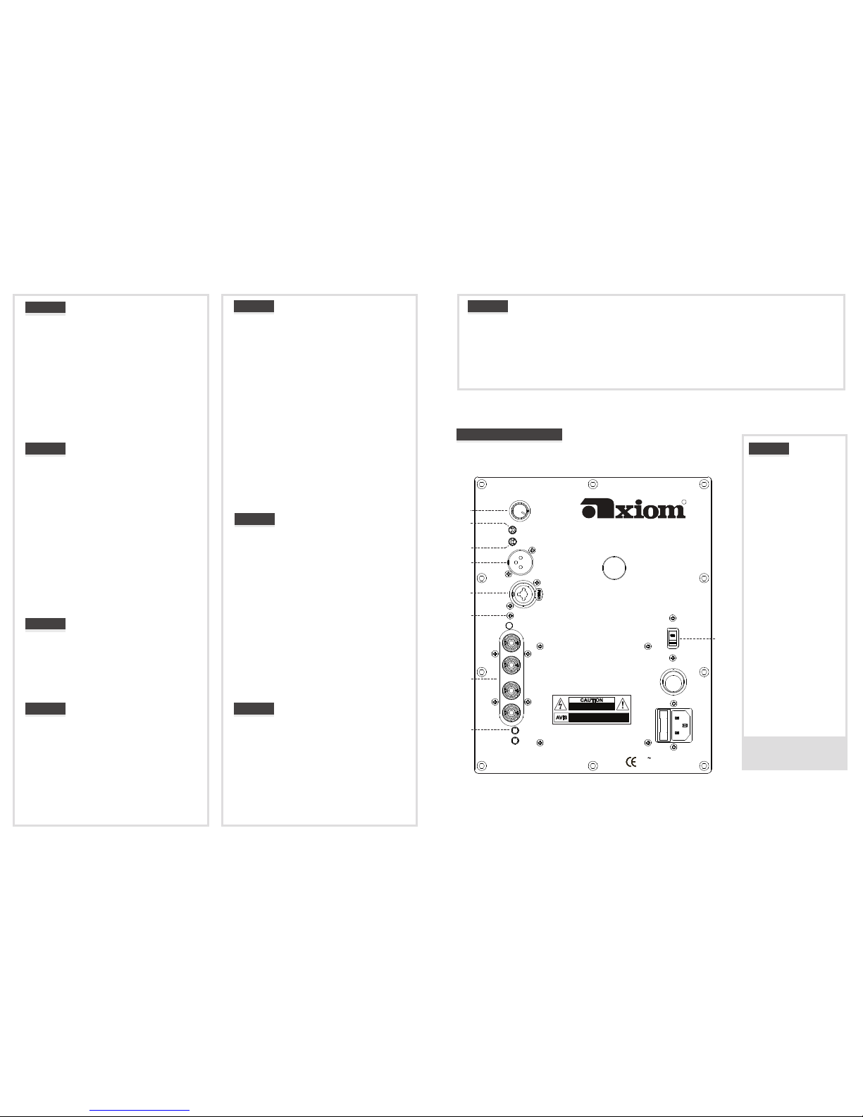
Step 4
Step 3
Step 7
Step 2
Step 1
Step 1A
Step 6
Step9
Step 5
I
0
Step 5:
Step 6:
Step 7: