Vent-Axia VAAR500 User manual

Opal
Aluminium Radiator
Heater Range
Stock Ref. N°
448469 VAAR500
448470 VAAR750
448471 VAAR1000
448472 VAAR1250
448473 VAAR1500
Installation and Wiring Instructions
PLEASE READ INSTRUCTIONS IN CONJUNCTION WITH ILLUSTRATIONS.
PLEASE SAVE THESE INSTRUCTIONS

2
* This appliance has been designed to be fixed to a wall. Please read these
instrucons carefully before starng the installaon.
* This heater is filled with a precise quanty of special oil. Repairs requiring the opening
of the heater should be carried out by a qualified service engineer.
* Never pull the power cord. Do not leave the power cord in contact with the appliance
while it is on.
* When the heater in ON make sure that it is kept away from any combusble material
such as curtains, carpets furniture, etc.
*
DO NOT COVER THE APPLIANCE. DO NOT USE IT TO DRY CLOTHES.
If it is covered there is an overheang risk.
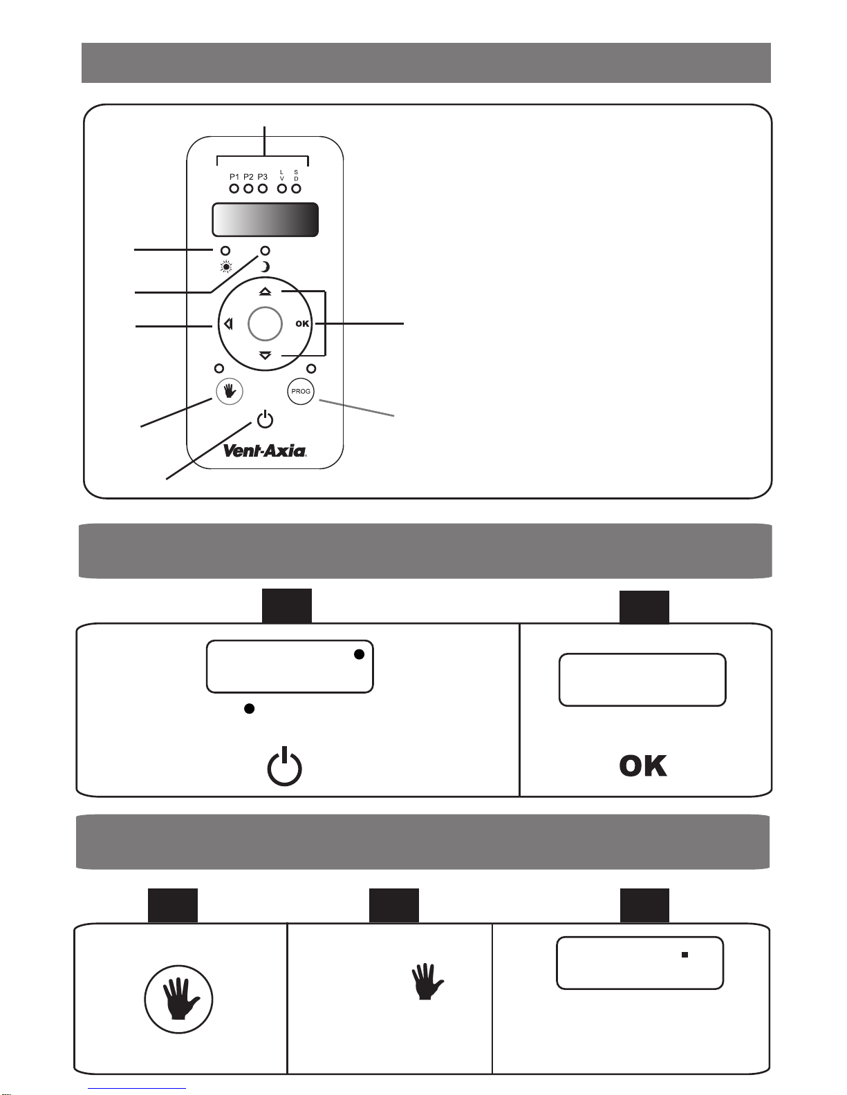
* In order to prevent children from modifying the heaters program sengs the heater,
incorporates a funcon to let you lock the controls.
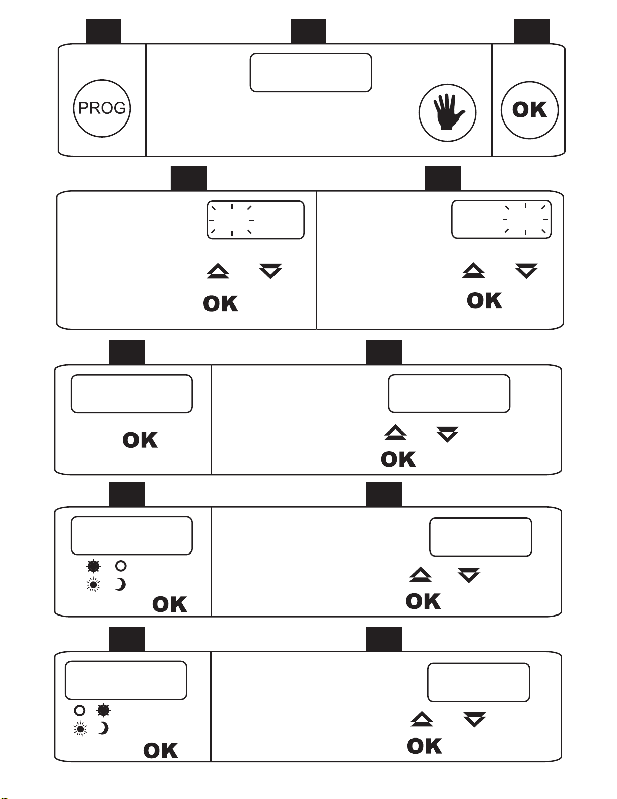
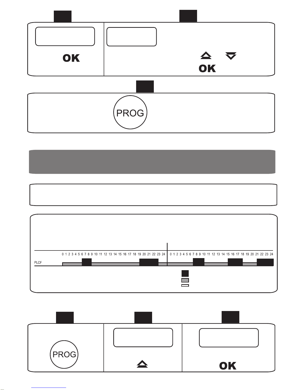
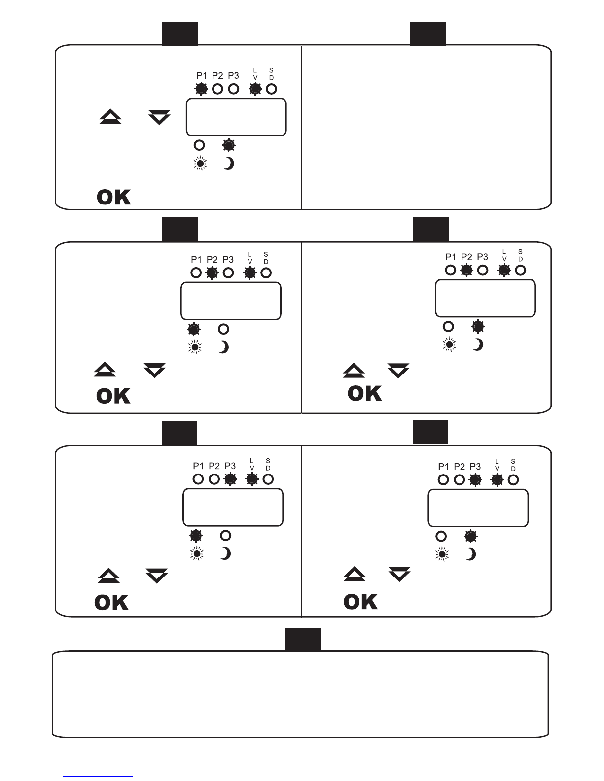
* To enter the programming mode the “PROG” key must be pressed for at least 2 seconds.
* DANGER: If the power supply cable is damaged, it should be replaced by the
manufacturer or any qualified person.
* The appliance must be installed in such a way that it is impossible for anyone using a
bath or shower, to touch the controls.
* The appliance should not be located under or in front of a power supply socket.
* This appliance must be connected to the supply by fixed wiring. The supply circuit to the
heater must incorporate a double pole isolang switch having a contact separaon of at
least 3 mm.
* Before carrying out any work on the heater. It must be disconnected from the supply.
* This heater should not be disposed of with household waste. Please recycle where
facilies exist. Please take account of the thermal fluid inside the unit.
* The installaon should be undertaken according to the correct rules regarding the
electric installaon.
* The appliance MUST be earthed.
* When fing this heater. Please respect the safety distances stated in this leaflet.
* The appliance is not intended for use by persons (including children) with reduced
physical, sensory or mental capabilies, or lack of experience and knowledge, unless
they have been given supervision or instrucon concerning use of appliance by a person
resposible for their safety. Children should be supervised to ensure that they do not play
with appliance.
1. GENERAL WARNINGS

3
MIN 15 cm
MIN 15 cmMIN 15 cm
MIN 15 cm
1
2
MIN 60 cm
MIN 60 cm
TEMPLATE
Minimum distances
To avoid problems it is necessary to keep a minimum distance of 15 cm between the
heater and any combusble materials.
2.1 It is important that the heater IS FIXED FIRMLY TO A SOLID AND LEVELLED WALL.
2.2 Make sure that there is a socket near the area where you are going to place it.
2.3 Take out from the box the paern to see the exact posion of the mounng screws.
3
4 SCREWS
4
2. INSTALLATION INSTRUCTIONS
PLACE THE
HEATER
(W)
500
750
1000
1250
1500
“A” (mm)
420
420
420
420
420
“B” (mm)
246
246
246
246
246
“C” (mm)
159
319
478
638
638

4
6
1
3
2
1. TO PLACE
2. TO LET
3. TO PLACE
7.1 Then connected the power supply cord to a double pole isolang switch.
7.2 Make sure that the heater is perfectly fixed to the wall to avoid future risks.
IMPORTANT:
To have the heater perfectly fixed to the wall, screw COMPLETELY the 6 x 50 mm screws in
the upper part of the separators (Point 6 - Fig. 4).
To avoid problems it is necessary to keep a minimum distance of 15 cm between the heater
and any combusble material such as curtains, furnitures, etc.
7
5
3. TECHNICAL INFORMATION
- Manual programming funcon. - 7 pre-set programmes.
- Configure your own heater program. - Comfort/ economic/ anfreeze modes.
- The controls can be locked. - Weekly programming.
- ON/ OFF Luminous display.
- This heater must be used on an ~ supply only and the voltage marked on the heater must
correspond to the supply voltage.
- Before wiring, please note that the wires in this mains lead are coloured inaccordance
with the following code:
2 SCREWS
FIXED HEATER
3. HEATER FUNCTIONS
4. ELECTRIC CONNECTION
Blue
Brown
Green - Yellow
Power Cord 240 V Supply
NEUTRAL
LIVE
EARTH

5
1. STANDBY
2. MANUAL MODE
3. PROGRAM MENU
4. NAVIGATION KEYS (+, -, OK)
5. ON / OFF FOR THE DISPLAY
6. ECONOMIC LED
7. COMFORT LED
8. PROGRAM SETTING LEDS
1
23
4
5
6
7
8
5.1 START UP
Press
=“Stand-by”
Press
Pr : Hd
12
5.2 MODE MANUAL
123
Press
The room temperature appears
The led is lit up
17.5
c
5 PROGRAMMING THE HEATER

6
Press
45
22.0
c
Press
Mark the desired comfort temperature, for example 22 ºC.
or
6
17.5
cThe actual room temperature will appear again.The heater will start
heating up till it reaches the marked temperature, in this case 22 ºC.
5.3 PROGRAMMING MODE
The heater is programmed with 7 plans during its manufacture which can be adapted to most
of the heating situations that you may need.The 7 plans are described below in the table nº 1.
The Plan nF is programmed for periods when you are away from your home during long periods of time
and would like to protect it against freezing.The green economy LED will flash.
TABLE Nº 1
Working Days Weekend
Comfort
Economy
Antifreeze
The UE Plan is a heating plan desired for weekends.With this plan the heater will work from monday
to thursday in the antifreeze position. In the period from friday to sunday you can configure a programme
according to your needs.

7
1 2 3
Press 2 seg.: Press:
45
Press
Programming the hour. Programming the minutes.
You can change the language (english, french, spanish)
pressing:
or or
Press Press
67
Press Press
Programme the day of the week.
or
Press
00 : 00
Hour
23 : 00
dAY dd Mo
89
Press
Press
Mark the desired comfort temperature.
or
Press
tº C 22.0 ºc
10 11
Press Press
Mark the desired economy temperature.
or
Press
tº E 18.0 ºc
Press

8
12 13
Press
Choose the programme or plan you desire.
or
Press
PLAn PL 01
14
Press
to put into action this plan.
Press
5.4 PLAN ACCORDING TO YOUR REQUIREMENTS
If none of the 7 programmes correspond to your heating needs,we are going to explain how you can
configure your own heating system plan.
1 2 3
Press 2 seg.
Press
Hour PLAn
Press
Example
Working Days Weekend
Comfort
Economy
Antifreeze

9
7 8
Press
Choose 06:00 h.
or
Press
06:00
9
Now we are going to introduce the start of the first economy period from monday to friday.The economy,
first period P1 and days monday to friday leds will light up. In our case,the first economy period starts at
9:00 h.
9
6
Now we are going to introduce the start of the first comfort period from monday to friday.The comfort
first period P1 and days monday to friday leds will light up. In our case,the first comfort period starts at
6:00 h.
45
Press
Choose the programme PLCF.
or
Press
PL CF

10
16
Now if you wish,you can programme the period regarding saturday and sunday.
10 11
Press
Choose 09:00 h.
or
Press
09:00
12
Now we are going to programme period P2 and
period P3.
Press
Choose 14:00 h.
or
Press
14:00
Press
Choose 18:00 h.
or
Press
18:00
14
13
Press
Choose 20:00 h.
or
Press
20:00
Press
Choose 24:00 h.
or
Press
24:00
15

11
17
When you finish programming,press the button“PROG”.The room temperature will
appear on the display.You have just designed a heating system plan.
6 SWITCHING OFF THE DISPLAY
IMPORTANT
If you do not require a set time period, you must put the hour of this period at“00:00”.
As you can see, we have not defined a third period between saturday and sunday.
To switch off the display press the button:
00:00 00:00
Press
If you wish to illuminate the display again, press any search button:
This option is cancelled when the heater is programmed in the anti-freeze plan“PLAH”.
IMPORTANT

12
7 LOCKING THE CONTROLS
8 STANDBY MODE
This mode will maintain all the program parameters.
9 DISCONNECTING THE ELECTRICAL SUPPLY FROM THE HEATER
If the switch-off time exceeds 24 hours, the current date and time will have to be re-programmed (PAG. 9).
Press:
=“Stand-by”
- To activate the function of locking the controls, touch simultaneously the keys (Fig. 1):
- To deactivate the function of locking the controls, touch simultaneously the keys (Fig. 2):
Loc unlo
FIG. 1 FIG. 2
10 POWER CONSUMPTION INDICATION
NOTE
If you wish to reset the counter, repeat steps 1 - 4 and press 3 seg.the key:
1 2 3
Press 3 seg.
Press
Hour WAt
Press
45
The approximate
consumption in KW will be indicated,
for example 3.3 KW
Press
003.3
The counter will reboot automatically every 30 days.


Head Office: Fleming Way, Crawley, West Sussex, RH10 9YX. Tel: 01293 526062 Fax: 01293 551188
UK NATIONAL CALL CENTRE, Newton Road, Crawley, West Sussex, RH10 9JA
SALES ENQUIRIES: Tel: 0844 8560590 Fax: 01293 565169
TECHNICAL SUPPORT: Tel: 0844 8560594 Fax: 01293 532814
As part of the policy of continuous product improvement Vent-Axia reserves the right to alter specifications without notice.
448500A 1111
The Guarantee
Applicable only to products installed and used in the United Kingdom. For details of guarantee outside the United Kingdom
contact your local supplier.
Vent-Axia guarantees its products for two years from date of purchase against faulty material or workmanship. In the event of
any part being found to be defective, the product will be repaired, or at the Company’s option replaced, without charge, provided
that the product:-
Has been installed and used in accordance with the instructions given with each unit.
Has not beenconnected to an unsuitable electricity supply. (The correct electricity supply voltage is shown on the
product rating label attached to the unit).
Has not beensubjected to misuse, neglect or damage.
Has not been modified or repaired by any person not authorised by the company.
IF CLAIMING UNDER TERMS OF GUARANTEE
Please return the complete product, carriage paid to your original supplier or nearest Vent-Axia Centre, by post or personal visit.
Please ensure that it is adequately packed and accompanied by a letter clearly marked “Guarantee Claim” stating the nature of
the fault and providing evidence of date and source of purchase.
The guarantee is offered to you as an extra benefit, and does not effect your legal rights
This manual suits for next models
4
Table of contents
Other Vent-Axia Swimming Pool Heater manuals
Popular Swimming Pool Heater manuals by other brands

Bestway
Bestway 58423 owner's manual

Amerec
Amerec 6.0M Installation and operating instructions

Raypak
Raypak 180A Illustrate parts list

Hayward
Hayward ABG1001 Installation, operation & service procedures

Hayward
Hayward H250IDL2 Installation, operation & service instructions

Nirvana
Nirvana ECO 50 owner's manual

Nibe
Nibe POOL 310 Installer manual

Waterco
Waterco ElectroHeat MKIV Installation and operation manual

Zodiac
Zodiac RED LINE Instructions for installation and use

ThermoTec
ThermoTec Pro Heat Pump Pool Heater Installation & operating instructions

EcoOnline
EcoOnline PoolMasterpro Installation and user manual

Brasch
Brasch BH-933 Series instructions