manuals.online logo
Brands
  1. Home
  2. •
  3. Brands
  4. •
  5. Vent-Axia
  6. •
  7. Ventilation Hood
  8. •
  9. Vent-Axia LoWatt HR204 User guide

Vent-Axia LoWatt HR204 User guide

Other Vent-Axia Ventilation Hood manuals

Vent-Axia silhouette-100 User manual

Vent-Axia

Vent-Axia silhouette-100 User manual

Vent-Axia MV250H(RF) User manual

Vent-Axia

Vent-Axia MV250H(RF) User manual

Vent-Axia Napoli User manual

Vent-Axia

Vent-Axia Napoli User manual

Vent-Axia Genova 120801A Technical manual

Vent-Axia

Vent-Axia Genova 120801A Technical manual

Vent-Axia LoWatt T-SERIES User manual

Vent-Axia

Vent-Axia LoWatt T-SERIES User manual

Vent-Axia Milano Technical manual

Vent-Axia

Vent-Axia Milano Technical manual

Popular Ventilation Hood manuals by other brands

Gorenje S3 IHGC963S4X manual

Gorenje

Gorenje S3 IHGC963S4X manual

KOBE ISX2136SQB-1 Installation instructions and operation manual

KOBE

KOBE ISX2136SQB-1 Installation instructions and operation manual

U.S. Products ADVANTAGE-100H Information & operating instructions

U.S. Products

U.S. Products ADVANTAGE-100H Information & operating instructions

Kuppersberg DUDL 4 LX Technical Passport

Kuppersberg

Kuppersberg DUDL 4 LX Technical Passport

Framtid HW280 manual

Framtid

Framtid HW280 manual

Thermador HGEW 36 FS installation manual

Thermador

Thermador HGEW 36 FS installation manual

Electrolux LFT769X user manual

Electrolux

Electrolux LFT769X user manual

AEG X69453MVO UK user manual

AEG

AEG X69453MVO UK user manual

Broan B5836SS manual

Broan

Broan B5836SS manual

Heinner HDCH-6060RGBK quick start guide

Heinner

Heinner HDCH-6060RGBK quick start guide

Baumatic AS35SS instruction manual

Baumatic

Baumatic AS35SS instruction manual

Franke FTF 604 XS V2 Instructions for use and installation

Franke

Franke FTF 604 XS V2 Instructions for use and installation

Best UCB3I30SBW installation instructions

Best

Best UCB3I30SBW installation instructions

Gram EFU 503-90 X instruction manual

Gram

Gram EFU 503-90 X instruction manual

CIARRA CBCS6803 Installation and user manual

CIARRA

CIARRA CBCS6803 Installation and user manual

sauter SHG501 Instructions for installation and use

sauter

sauter SHG501 Instructions for installation and use

Franke 392-17 User instructions

Franke

Franke 392-17 User instructions

FALMEC Polar Black 35 Instruction booklet

FALMEC

FALMEC Polar Black 35 Instruction booklet

manuals.online logo
manuals.online logoBrands
  • About & Mission
  • Contact us
  • Privacy Policy
  • Terms and Conditions

Copyright 2025 Manuals.Online. All Rights Reserved.

Please leave these instructions with the user
Whole House Ventilation System
with Heat Recovery
User, Installation & Servicing
Instructions
LoWatt HR204
ABC
2
Contents
Section Page
1.0 Safety and Guidance Notes
2.0 User Information
3.0 General Layout
4.0 Technical Data
5.0 Appliance Operation
6.0 Installation Requirements
7.0 Installation
8.0 Wiring Diagrams
9.0 Commissioning
10.0 Maintenance
11.0 Changing Components
12.0 Fault Finding
13.0 Short Parts List
3
4
5
6
8
9
12
15
18
19
20
22
24
3
1.0 Safety and Guidance Notes
1. DO NOT install this product in areas where
the following may be present or occur:
-Excessive oil or a grease laden atmosphere.
-Corrosive or flammable gases, liquids or
vapours.
-Ambient temperatures higher than 40°C or
less than 5°C.
-Possible obstructions which would hinder the
access or removal of the product.
2. All wiring to be in accordance with the current
I.E.E. Regulations, or the appropriate standards
of your country and MUST be installed by a
suitably qualified person.
3. The LoWatt HR204 and accessories should
be provided with a local isolator switch capable
of disconnecting all poles, having a contact
separation of at least 3mm.
4. Ensure that the mains supply (voltage,
frequency, and phase) complies with the rating
label.
5. The LoWatt HR204 should only be used in
conjunction with the appropriate Vent-Axia
accessories.
6.When the LoWatt HR204 is used to remove air
from a room containing a fuel-burning
appliance, ensure that the air replacement is
adequate for both the LoWatt HR204 and the
fuel-burning appliance.
7. The LoWatt HR204 should not be fitted where
it is liable to be subject to direct water spray.
8. This appliance is not intended for use by
persons (including children) with reduced
physical, sensory or mental capabilities, or lack
of experience and knowledge, unless they have
been given supervision or instruction
concerning use of the appliance by a person
responsible for their safety.
9. Children should be supervised to ensure that
they do not play with the appliance.
10. The power supply to the unit and its
accessories should always be switched off
before removing the cover or ducting.
4
2.0 User Information
Read the instructions fully before installing
or using the appliance.
This appliance must be installed in
accordance with the manufacturer's
instructions and the regulations in force.
The LoWatt HR204 is a mechanical ventilation
with heat recovery (MVHR) unit. The unit
provides continuous extraction of stale air
from the dwelling, typically from the
bathroom and from the kitchen. The stale
air passes through the heat exchanger
before being ducted to outside.
Fresh air from the outside is continuously
drawn into the unit and passed through a
filter and then into the heat exchanger. In
the heat exchanger the fresh air is pre-
warmed and ducted into the dwelling,
typically to living rooms / bedrooms.
Fig. 1
This product should not be disposed of with
household waste. Please recycle where
facilities exist. Check with your local
authority for recycling advice.
For cleaning and servicing instructions,
refer to section 9, page 19.
Exhaust
Out
Fresh Air
In
Hot Stale
Air In
Warm Air
Out
Applicable only to products installed and
used in the United Kingdom. For details of
the Guarantee outside of the United Kingdom
contact your local supplier.
Vent-Axia guarantees this product for two
years from the date of purchase against faulty
material or workmanship. In the event of any
part being found to be defective, the product
will be repaired, or at the Company's
discretion the product will be replaced
without charge, provided that the product:
1). Has been installed and used in
accordance with the instruction given with
each unit.
2). The electricity supply complies with the
rating label.
3). Has not been misused, neglected or
damaged.
4). Has not been modified or repaired by any
person not authorised to do so by Vent-Axia.
IF CLAIMING UNDER THE TERMS OF THE
GUARANTEE
Please return the complete product, carriage
paid to your original supplier by post or in
person. Please ensure that it is adequately
packed and accompanied by a letter clearly
marked 'Guarantee Claim' stating the nature
of the fault and providing proof of the date
and source of purchase.
2. 2 The Vent-Axia Guarantee
2. 1 General
5
3.0 General Layout
LoWatt HR 204
Exhaust
out to
atmosphere
Fresh air
in from
atmosphere
N
L
1
2
1 2 345678
Normal Boost
1 2 345456
ON
FRONT
UP
Hot stale air
extracted
in from
wet rooms
Warmed fresh
air supplied
out to
dry rooms
1
2
810 911
15
67
14
4
13 5
12
Fig. 2
3
1. Heat exchanger
2. Fan (fresh air in)
3. Rating label
4. Fuse
5. Speed select PCB
6. Accessory switch connection
7. Dip switch for speed selection
8. Lower fixing hole
9. Alternative outlet for condensate (bottom)
10. Condensate drain (Ø15mm)
11 Condensate tray
12 Alternative outlet for condensate (side)
13 Fan (extraction)
14. Air filter
15. Duct connections (4 off)
6
4.0 Technical Data
Dimensions (mm)
Height
Width
Depth
Minimum clearances (mm)
Both sides
Above casing
Below casing
Front for servicing
Front in operation
Lift weight (kg)
Power consumption @ 0Pa (watts)
Suitable for Ø100mm circular ducts.
Suitable for Ø15mm pipe.
220-240V ~50Hz
3 Amps
3.15 Amps
EU2
412
552
285
5
200
100
250
None
17
Speed 1
Speed 2
Speed 3
Speed 4
Speed 5
Speed 6
10
13
21
35
56
75
Duct connections
Condensate connection
Electrical supply
External fuse rating
Internal fuse rating
Filtration
Appliance must be connected to an earthed supply
Fig. 4
SAP Appendix Q Test Results
As tested and published by BRE (Building Research Establishment).
www.sap-appendixq.org.uk
Exhaust
terminal
configuration
Fan speed
setting
Total flow
supply rate (l/s)
Total exhaust
flow rate (l/s)
Specific fan
power (W/l/s)
Heat recovery
efficiency (%)
Kitchen + 1
additional wet
room
Kitchen + 2
additional wet
rooms
2
3
15.0
21.0
15.0
21.1
0.81
0.95
63
57
Fig. 3
7
4.0 Technical Data
412
552
Mounting
Brackets
Side View
Ø98
100
280
285
4
Lower
Fixing Hole
Exhaust
Out
Fresh Air
In
Hot Stale
Air In
Warm Air
Out
Air Flow System
Clean Air
Stale Air
Front View Fig. 6
Flow Rate Vs Pressure Chart
Fig. 5
The unit has six speeds. One of the lowest five can be selected for normal speed. One of the top 3 can be
selected for boost speed. The performance curve chart gives the ventilation rates at each fan speed compared
to the pressure drop of the system.
102
100Pa @
100m³/h
0
50
100
150
200
250
300
350
400
0 20 40 60 80 100 120 140 160 180 200
Pressure (Pa)
0 5 10 15 20 25 30 35 40 45 50
Volume (l/s)
55
Volume (m³/h)
Extract
Supply
1
2
3
4
5
6
8
5.0 Appliance Operation
On normal running the fans run at the speed
set during commissioning (speed 1, 2, 3, 4 or 5).
If the external controls call for boost operation
the fans automatically run at the boost speed &
increase the air movement of both exhaust &
inlet air.
Optional Extras.
External Controls.
Normal/boost
Switch
NBSW
Nm
oral
Bo tos
Humidity Sensor
HS6
Normal/boost
Pull Cord Switch
PCSW
CMSM control
TIM2 timer
The LoWatt HR204 can only be connected to
external controls with an uncommitted relay.
If the fans become jammed, then the
electronics will sense the reduction in speed
(rpm) and stop the electrical supply to the
motors to prevent overheating. The unit will
check the ability of the fan to rotate every
couple of seconds.
Air is then moved through the unit (see Fig 6).
Humidity Sensor
Ecotronic
9
6.0 Installation Requirements
6.1 Location and Site Requirements
All dimensions
in mm
Total required
(including clearances)
Height - 692
Width - 562
Depth - 530
Minimum top
clearance
for servicing
200
Minimum
side
clearance
5
Minimum
side
clearance
5
Minimum bottom
clearance
100
Minimum front
clearance
for servicing
250
Fig. 7
Clearances
1. Read the instructions fully before installing or
using the appliance.
2. The installation must be carried out in
accordance with the manufacturer's instructions
by a competent person and comply with the
relevant Building Regulations and the current
I.E.E Wiring Regulations.
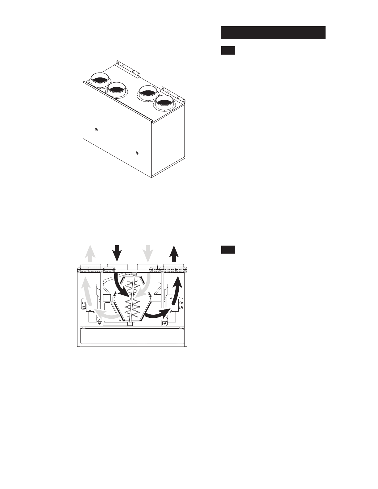
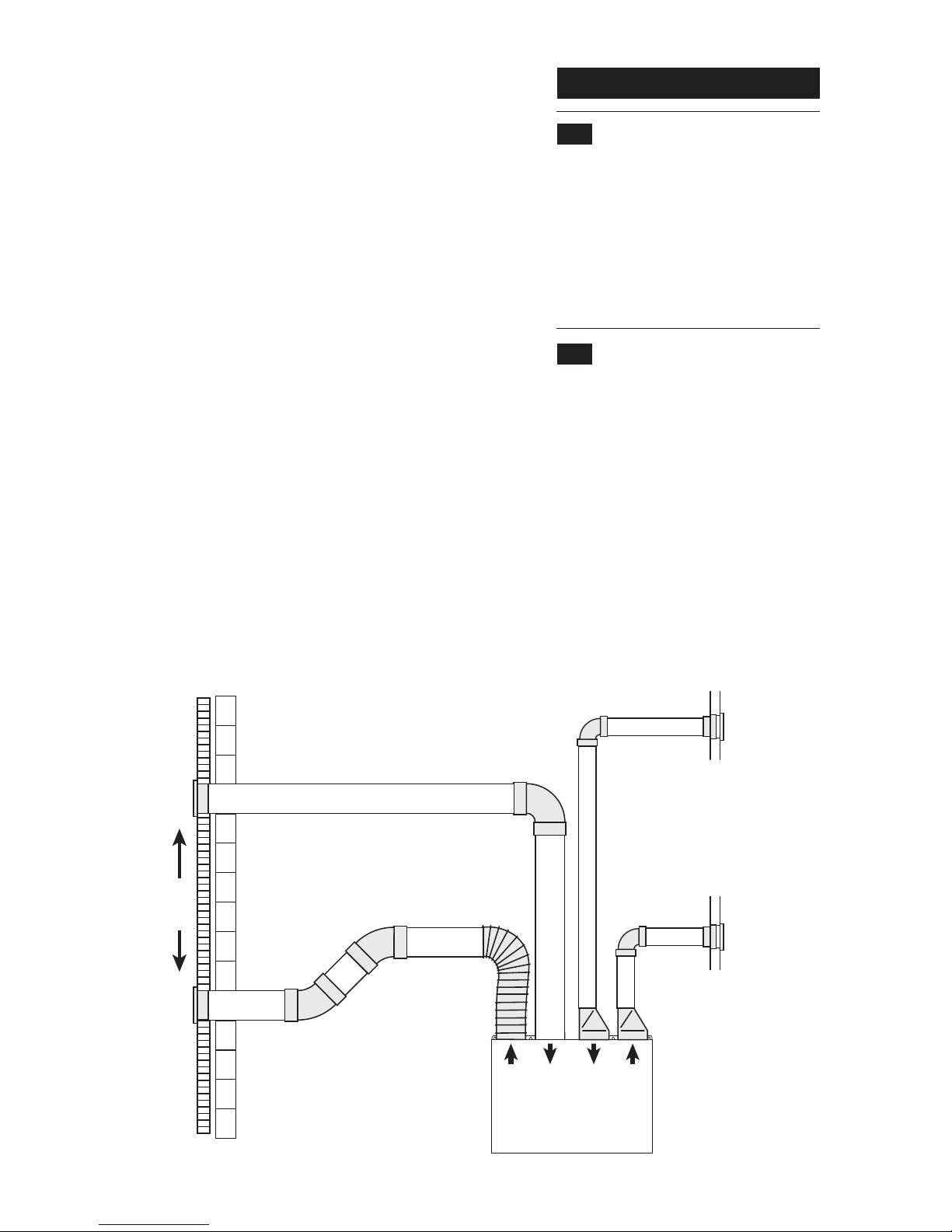
3. Duct systems should be installed in
accordance with BRE Digest 398 and CIBSE
guides.
4. Consideration must be given to the position
of the ductwork connections, the electrical
connection and the condensate pipe
connection.
5. The exhaust duct must pass through an
outside wall or roof and discharge to
atmosphere in a suitable position. The clean air
inlet duct must pass through an outside wall or
roof and be suitably positioned to provide an
adequate fresh air supply from atmosphere.
6. The ventilation for any open flued appliance
must always be considered before siting the
extract and inlet vents. The vents must also be
sited away from other flue terminals, ventilators
etc. on the outside of the dwelling. In addition,
there shall be adequate ventilation of the kitchen
when a cooker hood is used at the same time as
appliances burning gas or other fuel. The
exhaust air duct must not be discharged into a
flue which is used for exhausting fumes from
appliances burning gas or other fuels. Refer to
the relevant current British Standard Codes of
Practice, Part J of the Building Regulations
(England and Wales) and, in Scotland, OFTEC
Technical Information Sheet TI/112.
7. The LoWatt HR204 is not suitable for
installation above any cooking appliance or with
any extraction system servicing a cooking
appliance.
8. If the unit is fitted in a room containing a bath
or shower then reference should be made to the
current I.E.E Wiring Regulations.
9. A flat vertical area 692mm high x 562mm wide
is required for installation.
10. It is important that any door or cupboard
front covering the LoWatt HR204 is easily
removable by the user as access for regular
cleaning is required.
11. Check that the information on the rating
label is compatible with the supply. See Fig 2.
12. The addition of anything that may interfere
with the normal operation of the appliance could
invalidate the appliance warranty and infringe
regulations.
Note: Clearances do not take into
account any acoustic mat that may
be fitted between the unit and the
wall.
10
6.0 Installation Requirements
6.2 General
1. The LoWatt HR204 has a choice of 5 normal
speed settings and 3 boost speed settings. The
performance curve chart (Section 4, Fig.5)
gives the ventilation rates at each fan speed
setting compared to the pressure drop of the
system.
2. The transmission of noise along ducts should
be reduced by fitting noise attenuation ducts.
(FS100. Part No 370426.)
6. 3 Ducting
1. The outside exhaust duct and outside air
intake duct should be sited a minimum of 2
metres apart to minimise the risk of exhaust
air being drawn back into the house.
2. The duct work system should be sized and
installed to minimise the pressure loss along it.
3. Using larger diameter pipes and keeping the
number of bends and fittings used to a minimum
will reduce the pressure drop and allow the unit
to be set at a lower fan speed.
5. Ducting should be insulated in cold areas to
minimise heat losses. All duct joints should be
suitably taped to ensure an air tight seal.
Exhaust out
Fresh air in
Hot stale air in
Warm air out
Examples of different ducting & fittings
Bathroom
Living room or
bedroom
Terminals
minimum
2m apart
Outside
Wall
LoWatt HR204 Fig. 8
or kitchen
4. Bend radii for flexible ducting, measured to
the inside of bends, should be kept to at least
1x the duct diameter.