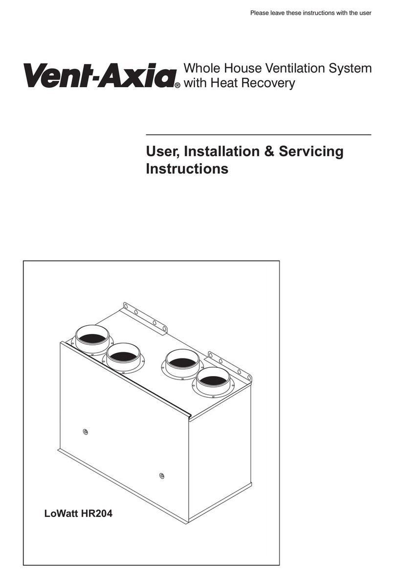
Vent-Axia Napoli User manual

230 / 240V 50Hz
PLEASE LEAVE THESE INSTRUCTIONS WITH END USER
EXTRACTOR HOOD
Please read all the instructions carefully
before starting the installation
abc
Model Stock Ref
Napoli 120812
Napoli Plus (white) 436083
Napoli Plus (Silver) 436084

PLEASE READ ALL INSTRUCTIONS CAREFULLY BEFORE STARTING INSTALLATION
THESE INSTRUCTIONS DESCRIBE THE VARIOUS TECHNICAL DETAILS OF YOUR EXTRACTOR
HOOD AND ITS USE
SAFETY
If the extractor hood is installed in a room containing a fuel burning appliance the installer must ensure that air
replacement is adequate for both the extractor hood fan and the fuel burning appliance.
Do not connect the extractor hood to chimneys, flues or air ducts serving the room.
Do not site where ambient temperatures are likely to exceed 50°C. Do no do any flambé cooking underneath the
hood. When frying, NEVER leave the pan unattended in case of fire. This appliance is not suitable for use above an
eye level grill.
Warning: Failure to comply with the cleaning instructions may result in a risk of fire. The appliance efficiency
depends on the condition of the filters.
All regulations and requirements MUST be strictly following to prevent hazards to life and property both
during and after installation, and during any subsequent servicing and maintenance.
GENERAL
This extractor hood can be installed above the cooking appliance in place of a standard wall cupboard. A matching
cupboard door panel, not supplied, should be mounted to the door panel of the extractor hood to ensure design
integration in your kitchen. Extraction of Recirculation modes are available.
The grease filter absorbs airborne grease particles so that kitchen furniture and walls remain relatively free of grease
and other particles that can cause unpleasant odours.
Extraction mode
For efficiency this mode is recommended since cooking smells, grease and steam are effectively removed from the
kitchen. The hood spigot must be connected to a duct to vent the extracted air outside. The spigot is compatible with
100mm diameter ducting. Ducting will be required to connect with the extract ducting. NB Remove the carbon odour
filter for maximum performance. The efficiency of the hood fan decreases as the length of the ducting and number of
bends increase.
If there are any horizontal areas in the extract ducting they must be angled at about 10° upwards towards the outside
of the building. Where an excessive amount of moisture is present in the air, a condensation trap may need to be
installed in the extract duct. Ducting passing through an unheated roof void should be insulated.
Recirculation mode
This mode is used if ducted extraction is not possible. The air passes through the grease filter first. Then odours are
reduced by the carbon filter before the air is recycled into the room. Please ensure that the carbon odour filter is fitted
in the hood.
The extractor hood outlet spigot must be connected with ducting to an outlet grille in the cupboard, which should direct
the filtered air away from the ceiling. Do not place the outlet grille too close to the hood intake otherwise the air
movement will be short circuited.
INSTALLATION
The hood must be mounted over the centre of the cooking area. The distance between the lowest part of the
extractor hood and the cooking surface must not be less than 760mm and not more than 900mm. Make sure the wall
can support the weight of the hood. (10.5kg).
Fastening the Extractor Hood to the wall, see figures 1 to 6.
Open the door panel by lifting it forwards. Remove the grille by pulling the grips F until free, then pull in the direction
shown in Figure 5. In Figure 1 notice the position of the catches J on the door side panels B. Push these catches
upwards as far as possible, Figure 6. Then remove the metal door by lifting it forwards and upwards.
See Figure 3. Using the dimensions given in Figure 2 as a guide, mark and then drill the four fixing holes for the 2
hooking plates P. The centre-lines for these holes are 567mm apart. Before drilling make sure that no wiring will be
damaged. Insert the wall plugs and securely fix the 2 hooking plates P to the wall with the 2 screws Q on each plate.

Cut a hole for the 100mm diameter ducting or grille. Lift the extractor hood and hook the wall brackets M onto the
hooking plates P.
See Figures 3 and 4. To obtain the required depth loosen the screws R, adjust the brackets M and re-tighten the
screws R. To adjust the depth on the lower end of the hood to match the bracket, loosen the screws G. Adjust the
moving spacer H until the hood is correctly lined up and re-tighten the screws G. Level the height of the hood by
loosening, adjusting, and re-tightening the screws L on the wall brackets M.
Attach the spigot to the air outlet. Securely fasten the ducting to the hood spigot and connect to the extract ducting or
grille. Ducting installation should conform to the requirements of the “General” section.
Secure the hood to adjacent cupboards to introducing the 8 counter-sunk screws through the side panels, from inside
the hood.
Mounting the Door Panel, See Figures 1 and 7
Mount the wooden door panel onto the metal hood door by lighting fitting the 2.9 x 12.7 screws in their holes as
shown in Figure 7/1.
Remount the door onto the hood by introducing the upper and lower slides into the guides. Close the door and adjust
the wooden door into line with the adjacent cupboards. Tighten the door screws, then remove the door again. Fully
tighten the screws and fit the remaining screws. Figure 7/2.
Remount the door onto the hood and push it until the first stop is reached, then push the catches J back down into
place. Reassemble the grille A by putting it into the slide N and pushing it up towards you. Then pull it down slightly
to ensure a correct fit.
WIRING
All electrical connections should be made by a properly qualified electrician. The extractor hood siting, wiring and
installation MUST comply with the current IEE Regulations (UK) or the appropriate standards in your country.
This product is manufactured to comply with the Radio Interference requirements of the EEC Directives. This
appliance is complete with mains lead and appropriate lamps.
WARNING: This appliance MUST NOT be earthed. It is double insulated. This appliance MUST be connected
to a 230-240V 50Hz AC single phase mains supply. ENSURE THAT THE MAINS SUPPLY IS ISOLATED
BEFORE MAKING ELECTRICAL CONNECTIONS.
Wiring should be via a switched spur with a 3A fuse (UK).
The installation MUST be provided with a double pole insulator switch with a contact separation of a least 3mm.
Alternatively a suitable 3 pin plug may be used.
For fixed wiring circuits the protective fuse for the appliance must not exceed 5A (UK). Where the appliance is
intended to be connected via a plug and flexible mains lead an approved plug must be used. UK: If an approved 13A
(BS1363) plus is used it must be fitted with a 3A fuse (BA1362).
IMPORTANT
The wires in the mains lead are coloured in accordance with the following code:
BLUE-NEUTRAL, BROWN – LIVE
These wire colours may not match the coloured markings identifying the terminals of your plug, in which case follow
the procedure below:
The BLUE coloured wire must be connected to the terminal marked with the letter N or coloured Black.
The BROWN coloured wire must be connected to the terminal marked with the letter L or coloured Red.
NEITHER WIRE is to be connected to the Earth terminal of a 3 pin plug marked with the letter E, or by the Earth
symbol ± or coloured Green of coloured Green and Yellow.
NB double check the wiring and make sure all connections are secure before switching the mains supply back on.
USING THE EXRACTOR HOOD, See Figures 1 and 8
The extractor hood should be switched on either before or at the same time as cooking or frying commences. The
grease and carbon filters are more effective if the fan is left running for about 20 to 30 minutes after cooking is
complete.
The appliance is fitted with a microswitch to sense when the hood door is open. When the hood door is closed the fan
will not run.

To switch on/off the mains to the appliance: Use the switch D. When this switch is off “0” neither the lighting nor the
fan switches will work.
To switch on/off the extractor hood lighting: If switch D is on “1” then switch C turns the lighting on and off. The
lamps work independently on the fan and hood door.
To switch on/off the extractor hood fan: If switch D is on “1” then switch E turns the fan on/off and varies the speed.
Opening the hood door will start the fan running at the speed selected by E. Closing the hood door turns the fan off.
CLEANING AND MAINTENANCE
WARNING: ALWAYS ENSURE THAT THE MAINS SUPPLY IS ISOLATED FIRST.
General Cleaning.
As often as needed, wipe the outside of the extractor hood with a sponge soaked in mild liquid detergent. Do not use
harsh cleaning chemicals or products with abrasives.
NB The appliance efficiency depends on the condition of the filters.
Acrylic Grease Filter, See Figure 9.
This filter absorbs airborne grease particles and should be washed every thirty days of hood operation, or at more or
less frequent intervals depending on how often the hood is used.
ISOLATE the mains supply. Open the door panel by lifting it forwards. Remove the grille by pulling the grips F until
free, then pull in the direction shown in Figure 5. Release the two wires Y and remove the filter material K.
Gently wash the filter by hand in warm soapy water, rinse thoroughly and carefully press on a cloth to dry. DO NOT
WRING THE FILTER. Clean the grease filter frame and grille with mild liquid detergent.
Replacing the grease filter: either replace the washed filter or cut a new piece of the material to fit the frame.
Reassemble the appliance.
Carbon Odour Filter, See Figure 10
This filter is needed for recirculation mode. The air passes through the active carbon filter and is cleaned before
recirculation into the room. THIS FILTER CANNOT BE WASHED. It must be replaced about twice a year, depending
on how often the hood is used.
Replacing the carbon filter: ISOLATE the mains supply. Open the door panel by lifting it forward. Remove the grille
by pulling the grips F until free, then pull in the direction shown in Figure 5. Turn the filter Z anti-clockwise to remove
the old filter. Insert the new filter and turn it clockwise to engage. Reassemble the appliance.
Lamp replacement
ISOLATE the mains supply. Open the door panel by lifting it forwards. Remove the grille by pulling the grips F until
free, then pull in the direction shown in Figure 5. If the lamp(s) fail to light when correctly following the instructions for
use above, first check that they are screwed in tightly. Reassemble the appliance.
The lamps must only be candle type as originally supplied or tubular type. (replacement Part No. 451133). Never use
lamps with a higher rating than that indicated on the extractor hood lamp lens.


VENT-AXIA CONTACT NUMBERS
UK NATIONAL SALES CENTRE
Domestic & Commercial Industrial
Tele: 01293 530202 Tele: 01293 441570
Fax: 01293 565169 Fax: 01293 534898
REPUBLIC OF IRELAND
Vent-Axia Ventilation Ltd.
Tele: (01) 450 4133 Fax: (01) 450 4570
UK NATIONAL TECHNICAL SUPPORT
Domestic & Commercial Industrial
Tele: 01293 526062 Tele: 01293 455196
Fax: 01293 551188 Fax: 01293 455197
The Vent-Axia Guarantee
Applicable only to products installed and used in the United Kingdom. For details of the Guarantee outside of the United Kingdom contact your local
supplier.
Vent-Axia guarantees this product for one year from the date of purchase against faulty material or workmanship. In the event of any part being
found to be defective, the product will be repaired, or at the Company’s discretion the product will be replaced without charge, provided that the
product:
1). Has been installed and used in accordance with the instruction given with each unit.
2). The electricity supply complies with the rating label.
3). Has not been misused, neglected or damaged.
4). Has not been modified or repaired by any person not authorized to do so by Vent-Axia.
If claiming under terms of guarantee
Please return the complete product, carriage paid to your original supplier or nearest vent-axia centre, by post or personal visit. Please ensure that
it is adequately packed and accompanied by a letter clearly marked “Guarantee claim” stating the nature of the fault and providing evidence of date
and source of purchase.
The guarantee is offered to you as an extra benefit, and does not affect your legal rights
As part of the policy of continuous product improvement
Vent-Axia reserve the right to alter specifications without notice
abc
Head Office:- Fleming Way, Crawley, West Sussex RH10 9YX
Tel:- 01293 526062 Fax:-01293 551188
466741 E 0307
This manual suits for next models
1
Table of contents
Other Vent-Axia Ventilation Hood manuals
