Ventenna HFp Vertical User manual

HFp Antenna User’s Guide
User’s Guide
7 MHz – 54 MHz Amateur Radio Antenna
HFp
Vertical
entenna
The Ventenna Co. LLC
P.O. Box 227
Huston, D 83630
www.ventenna.com

HFp Antenna User’s Guide
Page 2
Table of Contents
The HFp Antenna
------------------------------------------------------------------------------------------------------
3
HFp Vertical Parts List
-----------------------------------------------------------------------------------------
4
Assembling the antenna for use
---------------------------------------------------------------------
5
HFp Vertical Configuration Table
---------------------------------------------------------------
6
lement Stack Assembly
------------------------------------------------------------------------------------
7
Fine Tuning
-------------------------------------------------------------------------------------------------------------------
7
HFp Antenna Notes
-------------------------------------------------------------------------------------------------
8
Antennas
---------------------------------------------------------------------------------------------------------
8
Frequency Adjustments
----------------------------------------------------------------------
8
HFp Radials
-------------------------------------------------------------------------------------------------
9
Guy Lines
------------------------------------------------------------------------------------------------------
9
The HFp Wrench
------------------------------------------------------------------------------------
10
HFp Hints and Kinks
---------------------------------------------------------------------------------------------
11
lement Inserts and I Cs
-----------------------------------------------------------------
11
Waterproofing the Pigtail
-----------------------------------------------------------------
11
SWR (Standing Wave Ratio)
--------------------------------------------------------
11
Loose lement Inserts
------------------------------------------------------------------------
12
HFp-V Options
-----------------------------------------------------------------------------------------------------------
12
Here is the HFp -
Vertical antenna,
assembled in its 40
Meter configuration,
with included guy lines
attached.
It’s about 9 feet tall –
you can just see the top
whip against the tree
background.
If the guy lines were
black, it would almost
completely disappear!

HFp Antenna User’s Guide
Page 3
The HFp Antenna
The HFp design provides a highly efficient vertically polarized antenna design in an extremely
portable package - the entire kit weighs about 2.5 pounds (1 kg). The antenna is highly
configurable, and covers all the Amateur bands from 7 MHz to 54 MHz (as well as most of the
frequencies in between). An add-on option is available which covers 60, 75 and 80 Meters.
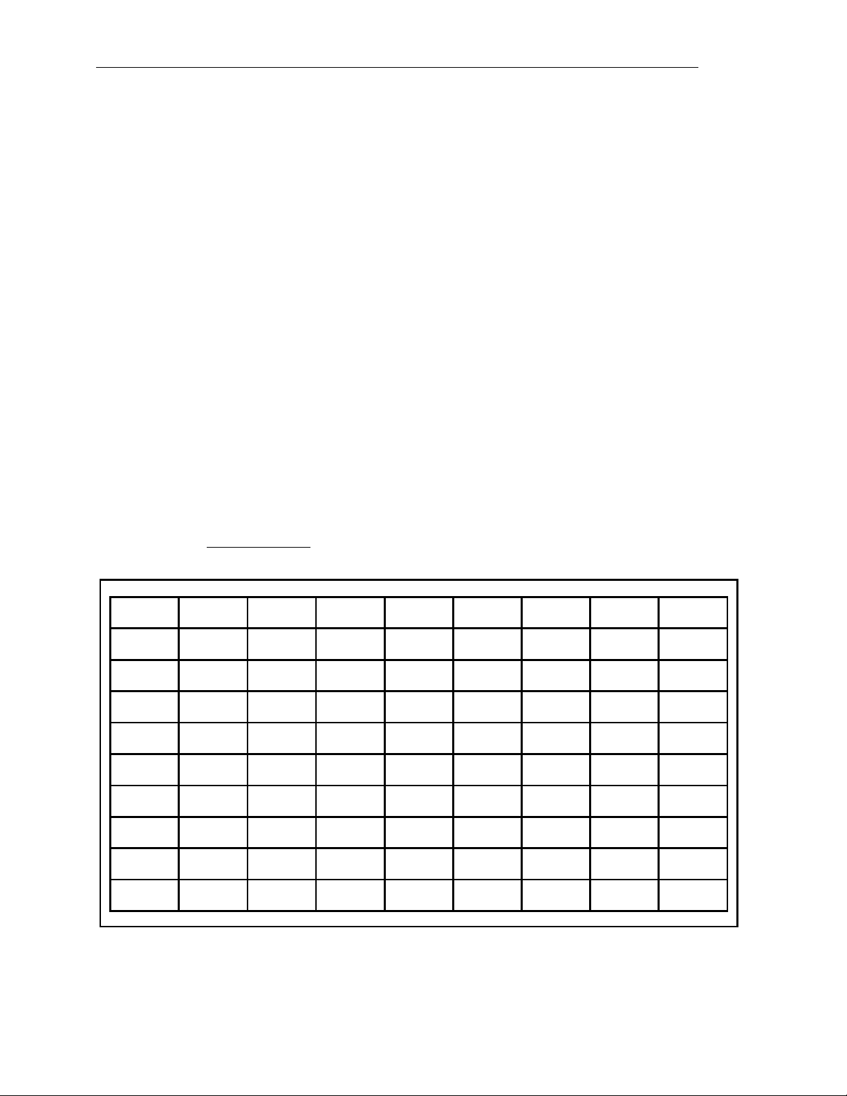
In this User’s Guide, you will find setup configurations for each Ham band from 40 Meters
through Six Meters, for the antenna sitting on the ground. If the antenna is on a balcony, or
mounted with the optional BackPack Mount Kit, you can use the configuration table as a starting
point, but you will need to experiment to get the setup right with the different mounting. There
is also a laminated card in the antenna bag, with the Ham Band configuration tables on it. The
card makes it easy to take the basic setup information with you on your portable operation trips.
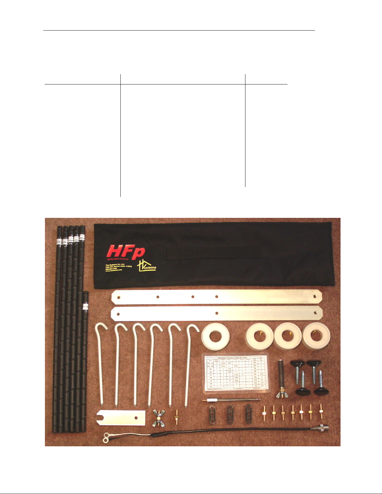
The antenna is configured for different bands by the selection and orientation of the six elements
that are included in the kit. Three of the elements are marked with a single stripe and contain no
loading coil. One element is marked with two stripes and contains a small inductive load near
one end. One element is marked with three stripes and contains a larger inductive load near one
end. And one element is about 2/3 the length of the others, and has no stripe or load. The
elements are coupled together by means of threaded brass Inter- lement Connectors (I Cs).
In addition to using combinations of elements, the orientation of the loaded elements (the two-
and three-stripe elements), with the striped end either UP or DOWN, determines the operating
frequency. In the configuration table later in the User’s Guide, as well as on the laminated
configuration card, you will see elements marked, for example, “2-stripe up”. If you assem le
these elements in the wrong orientation, the antenna will not tune to the desired frequency.
The one-stripe and zero-stripe elements have no orientation, and may be assembled into the
antenna either “up” or “down”.
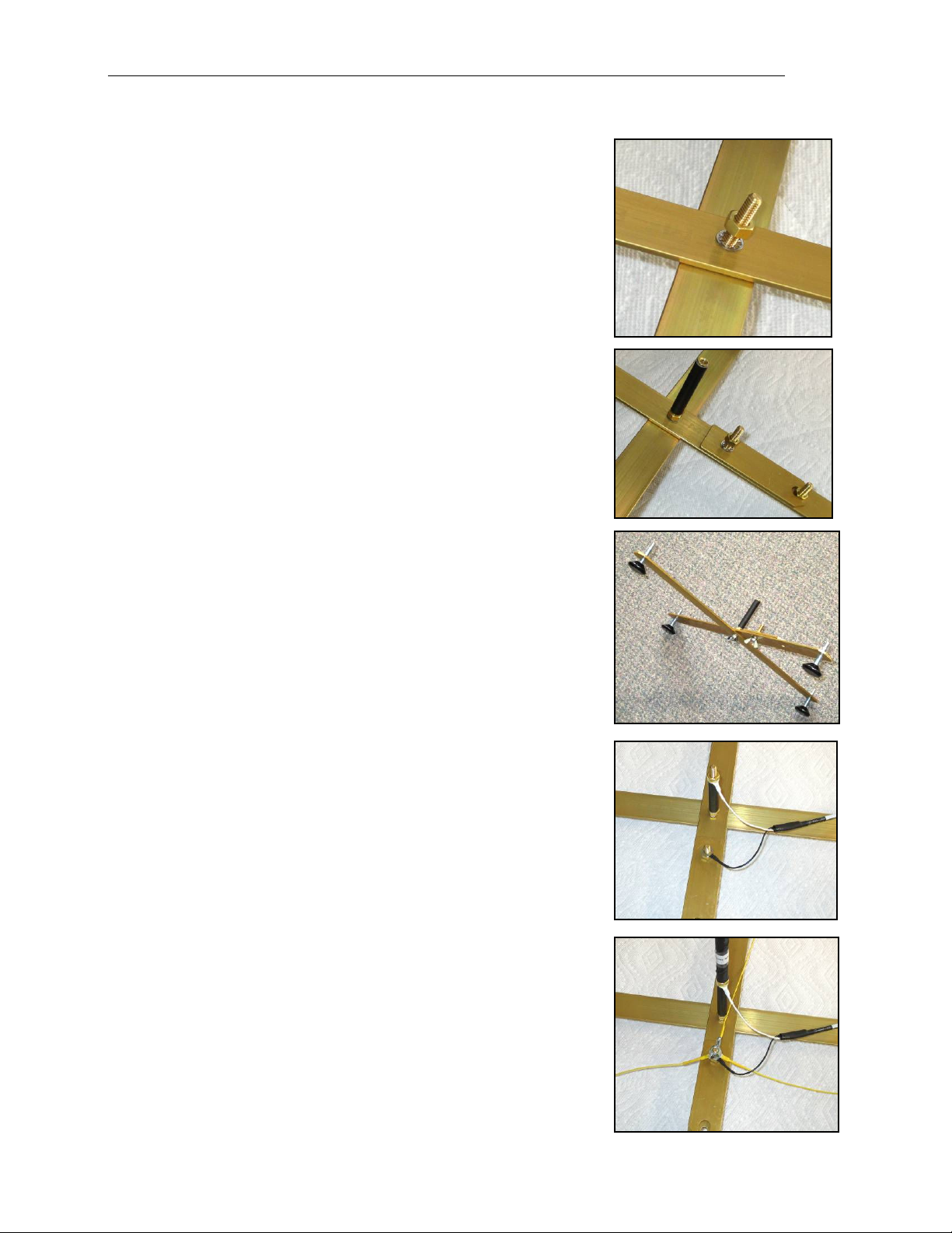
The HFp is designed to operate optimally with three tuned radial wires. We have found, after
much testing, that less than three wires reduces the antenna's effectivity, and more than three
doesn't seem to add much. The antenna will certainly radiate with one or two radials, but unless
you are hanging from a cliff, it is worth the time to set up all three. The radial wires are coiled
on plastic spools, and are marked in several places along their length. In use, the ring terminal is
attached to the antenna base, and the wire is un-spooled to the correct mark for the band in use,
as indicated in the Configuration Chart. This length is the “tuned length” for the radial wire, not
the quarter-wave length, and can later be adjusted for the lowest SWR.
Guy lines are included with the HFp for use when it is windy, or when the antenna will be left up
for some time. It is recommended that the guys always be used for the 40 meter configuration.
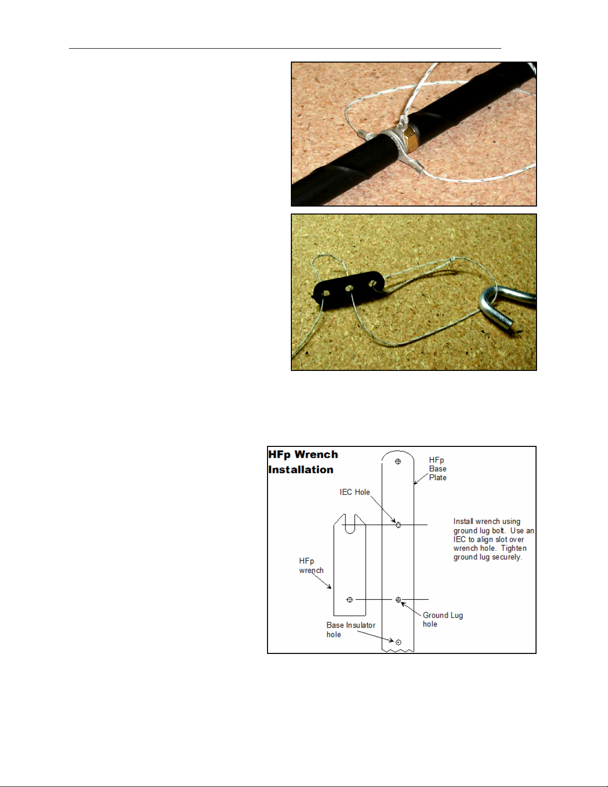
The guy lines have lug rings which are placed between two of the upright elements (typically
between the fourth and fifth elements from the bottom), using a special I C. The lines are then
run out to their full length and secured with the aluminum stakes provided, or tied to a handy
rock. Some small flag material attached to the guys will help prevent people from walking into
them. If the guys are run in the same direction as the radial wires, they will help protect the
radials from being tripped upon, as well. The Guy Line Sliders make adjusting the guy lines
very easy. (See Page 10)
You will need a length of coax to go from the HFp to your radio location. It should be long
enough so that you are at least a half-wavelength away at the lowest operating frequency. RG-58
has acceptable loss at these frequencies, and can be used for up to 100 Watts of power.

HFp Antenna User’s Guide
Page 4
HFp Vertical Parts List
Before assembling your antenna, verify that you have all the parts in the list below:
tem Description Quantity tem Description Quantity
Zero-stripe element 1 Base Plate 2
One-stripe element 3 Base Feet 4
Two-stripe element 1 Coaxial Pigtail 1
Three-stripe element 1 Radial Wire Spool 3
Collapsible Whip 1 Guy Line Spool 1
Inter- lement
Connector (I C) 7 Radial/Guy Stake 6
Base Insulator 1 Laminated Setup Card
1
Ground Lug Assembly
1 Guy Line Sliders 3
HFp Wrench 1 Special I C 1

HFp Antenna User’s Guide
Page 5
Assembling the Antenna for Use
1) First, screw the four feet into the ends of the aluminum base
pieces. After the HFp is set up, you can adjust these feet to make
it vertical, so it looks good.
2) Place a lock washer on an I C, and, from the top, insert the
I C stud with the washer through the center holes in oth base
plates.
Place a wing nut on the bottom of the I C, align the plates to be
at right angles, and tighten the wing nut.
Screw the Base Insulator onto the top of the I C.
3) Place the Wrench on the top of the plate, with the mounting
hole aligned with the hole just offset from the center hole in one
of the base pieces.
Put a lock washer on an I C, and put the I C stud with the
washer through the Wrench hole and the Base Plate hole. Use
another I C to position the wrench slot correctly over the I C
removal hole.
4) Use one of the Wing Nuts on the bottom of the Base Plate to
hold the I C and Wrench in position.
5) Screw an Inter- lement Connector (I C) into the top of the
Base Insulator, and place the center conductor lug of the coaxial
pigtail (the white wire) over the I C. (Under the I C is also
OK)
6) Put the coax shield lug (the black wire) on the ground stud,
put on one of the flat washers, then screw the wing nut on top of
it - not tight - you will need to take it off in a minute. Then place
the base on the ground or another flat surface.
7) Take off the Ground Lug wing nut and put the lugs from each
of the three radial wires over the ground lug, then the second flat
washer on top, them put the wing nut on loosely.
Arrange the Radial Wires at about 120 degree equally-spaced
triangular pattern from the lug and tighten the wing nut. Leave
the wires spooled for now.
8) Next, use the Configuration Table on the next page, or the
Laminated Card to determine which radiator elements you need
for the frequency band on which you wish to operate, and their
assembly sequence.
Get these elements, and the I Cs, ready to assemble.

HFp Antenna User’s Guide
Page 6
HFp Vertical Configuration Ta le
This is the Configuration Table for the HFp sitting on the ground, out in the open. The same
table appears on the Laminated Card.
Note that the length specifications for the extendable whip are in “Sections”. The whip fully
collapsed is one “section” long. The whip fully extended is six “sections” long.
ach different configuration calls out specific settings for the lements, the Radial Wires, and
the Whip. But, it is important to remember that these settings were determined with the HFp set
up in an open area, away from any objects.
The HFp may be affected by nearby objects (within a half-wavelength) in any particular location,
and the specified settings may need to be modified. If this is the case, the settings in the
Configuration Table may be deemed “starting points” for resonating the HFp at your frequency.
In some situations, where there are nearby objects strongly affecting the antenna’s resonant
frequency (typically lowering it), shortening the whip all the way may still not bring the SWR to
its lowest level. If this is the case, you may have to re-configure the elements. See the
"Frequency Adjustments" section for information on how to change the antenna configuration to
raise or lower the antenna’s frequency.
Be sure to notice the orientation of the stripes on the two-stripe and three-stripe elements. They
are always specified as “stripes-up” or “stripes-down”. Remember that the one-stripe and zero-
stripe elements may be assembled either “up” or “down”.
In the table, the bottom element is the one screwed onto the base insulator.
03/08/12
Bottom Element Element Element Element Element Radial Whip
Element 2 3 4 5 6 Length Length
© 2009 The Ventenna Co., LLC www.ventenna.com 1-888-624-7069
2.5- - - - - - 1st
6M
1 0 - -
HFp Vertical - Ham Band Configuration Chart
- - 2.5
5
3rd
2nd
- -
- -
- -
- - 2.5
5th
4th
4
0 3-Up 31
8th
8th
0
- -
11
1
11
40M CW
40M SSB
1
2-Dn
1
2-Dn1
20M
1
1
1
1
1
10M
0
17M
15M
12M
1
0
1
1
1
Band
30M
13-Dn
0 3-Up 1
2-Dn
5- -
- - 6th
7th
3
0
- -
2.75
1 0
2-Up
2-Up
2-Up1 - -
A chart listing configurations for all the frequencies the HFp can cover is available on the
Ventenna website, at http://www.ventenna.com/Manuals.html.

HFp Antenna User’s Guide
Page 7
Element Stack Assem ly
Using the Configuration Table, extend the whip to the correct length for the band. (Remember –
fully collapsed is one “section”.) Screw the whip into the top element.
Screw the bottom element for the band you want onto the base insulator I C (finger tight, not
wrench tight). Note that the "Bottom" element will always be a One- or Zero-Stripe element, to
keep the high-current node as high in the element stack as possible. Hint - For 40 and 80 meters,
you might want to put 2 or 3 elements on the bottom first - the stack can get pretty tall.
Using the threaded inter-element connectors, assemble the remaining elements (all finger-tight) -
then screw the assembled element stack onto the bottom element(s).
IMPORTANT NOTE - If it is windy, you should use the guy lines to secure the antenna. To do
so, use the Special I C between two of the upper elements - about head high, or just above, in
the stack. Put the Guy Line lugs on the sleeve of the Special I C. See the Guy Line details on
Page 9. (We recommend you always do this for 40m and longer configurations, or if you are
going to leave the HFp up for a while… the wind can come up quickly.)
Unwind the radial wires to the proper mark (from the Laminated Card) and stake the spools
down with the provided stakes (or use rocks to weigh them down). You should try to evenly
space the radial wires — place them approximately a 120 degree angles from each other.
Fine Tuning
The best method to fine-tune the HFp is to use one of the portable antenna analyzers. There are a
number of these available from MFJ, A A, Autek and others. A list comparing the different
models and prices can be found at http://www.eham.net/reviews/products/31.
Set up the HFp, with the extension cable you intend to use to connect it to your radio, and set the
analyzer for a frequency range which includes your target frequency. There should be a null in
the response at or near the target frequency. Adjust the whip to put it right on target.
If the null is out of the whip adjustment range, you will have to re-configure the elements to
bring it closer. Use the techniques in Frequency Adjustments (on Page 8) to change the antenna
configuration to raise or lower the antenna’s frequency. When you get close, use the whip
adjustment to refine the SWR to the best reading.
You can also use your radio to set up the antenna. This is less desirable because it has the
potential to generate some interference to other stations, so you should only use it if you have no
other choice. The procedure is as follows:
1. Set up the HFp according to the chart for the band of interest.
2. Set the radio to AM mode, and for SWR indication. If the radio has adjustable power,
use a low power setting.
3. Transmit a very short carrier at the low end of the band. Note the SWR reading.
4. Transmit a very short carrier in the middle of the band. Note the SWR reading.
5. Transmit a very short carrier at the top end of the band. Note the SWR reading.
Ideally, the SWR should be lowest at the middle of the band, and higher toward the top and
toward the bottom of the band. If the SWR is not acceptable in the band, then do the next steps.

HFp Antenna User’s Guide
Page 8
6. If the SWR is lower at the ottom of the band, and increases through the band, then the
antenna is resonant at too low a frequency. Shorten the antenna whip one section, and do
steps 3) through 5) again.
7. If the SWR is lower at the top of the band, and increases through the band, then the
antenna is resonant at too high a frequency. Lengthen the antenna whip one section, and
do steps 3) through 5) again.
If changing the whip length does not get the SWR to an acceptable level at your operating
frequency, then the antenna will need to be re-configured.
Use the techniques in "Frequency Adjustments" to change the antenna configuration to raise or
lower the antenna’s frequency. After each change, do steps 3) through 5) again.
When you get close, use the whip adjustment to refine the SWR to the best reading.
HFp Antenna Notes
The following notes can ease your setup, as well as provide you with ideas for experimentation.
While we have defined configurations for the ham bands, you can arrange the elements into other
configurations to cover the same, or other bands. In fact, the HFp Vertical can be configured to
ANY frequency between about 6.5 and 65 MHz (down to about 3.5 MHz when using the 80M
coil). We encourage you to experiment. If you find interesting configurations, please email us
and tell us about your experiments at <[email protected]>.
Antennas
Any antenna truly worth the name will exhibit as large a “capture area” as possible. That is, it
will present the largest possible amount of resonant structure to capture (or radiate) signals. The
larger the “capture area” the better the antenna works. The HFp configurations shown in the
configuration charts were designed to have large capture areas, but it is possible to achieve a
resonant antenna in a smaller assemblage of the elements, if having a smaller physical structure
is desired. xperimenting with the mix of elements may result in different combinations of
elements for any particular frequency. Just remember that the shorter antenna won’t reach out
quite as far as the longer one.
Frequency Adjustments
Note - If you need to adjust the resonant frequency of the HFp because nearby objects are
affecting it, most likely the resonant frequency will have to be raised.
1. Raising the resonant frequency – Moving an inductive load position higher in the
antenna will raise the frequency. This can be accomplished by turning over one of the
loaded elements (putting the stripes “up”), or moving it up in the assembly of elements.
Shortening the antenna by removing a zero- or a 1-stripe element, or replacing a 1-stripe
element with the zero-stripe will also raise the resonant frequency. And shortening the
whip will raise the resonant frequency.

HFp Antenna User’s Guide
Page 9
2. Lowering the resonant frequency – Moving an inductive load position lower in the
antenna will lower the frequency. This can be accomplished by turning over one of the
loaded elements (putting the stripes “down”), or moving it down in the assembly of
elements.
Adding a zero- or a 1-stripe element (making the antenna longer) will also lower the
resonant frequency. And extending the whip will lower the resonant frequency.
The HFp Radials
The HFp configuration charts define the tuned length radials for each Ham band, over
moderately damp, conductive ground. These tuned lengths are an important concept in the
proper operation of a ground-mounted vertical antenna. A write-up available on the Ventenna
web site explains the effect of different radial lengths and especially the problems which can be
generated by radials that are too long. Go to "http://www.ventenna.com/Manuals.html", and
download “Radials for ground-mounted Verticals”.
Although we have determined that the HFp will usually operate properly with the three radials
provided, adding radials may help lower the SWR in some situations, particularly in elevated
mount installations or over very dry or stony ground. It is easy to add extra wire to the radial
system to see what effect more radials might have.
You can also affect the performance of your antenna by lengthening or shortening the tuned
radials. Change all the radials the same amount, a little at a time, and follow the “Fine Tuning”
procedure to check SWR. Also, see the "SWR" discussion at the end of this manual.
In the “Radials for ground-mounted Verticals” write-up, you will notice that there is a broad
range of length for the radials which will provide good SWR. Because of this, it is possible to
use one length setting for multiple bands.
Guy Lines for the HFp Antenna
Use of the included Guy Lines is recommended if
you intend to leave the antenna up for any length of
time, or if it is windy. Although the antenna is
quite robust, and can withstand strong winds, it
will tip over (and probably damage the whip) under
windy conditions if it is not guyed.
A Special I C (Inter- lement-Connector), which
has a short sleeve on it, is used to allow the
element stack to rotate with the Guy Lines
attached. The short sleeve provides a small space
between the element and the nut in the center of the
I C. The sleeve is crimped in place on the
threaded portion of the I C.
The ring crimped to one end of each Guy Line has
an opening large enough to allow it to fit loosely over the Special I C sleeve. Because of the
loose fit, the three rings can rotate freely when the element stack is turned, preventing the guy
lines from wrapping around the element stack.

HFp Antenna User’s Guide
Page 10
Here is a picture showing two elements, the
Special I C, and the three Guy Lines
assembled together. This connection point
for the Guy Lines is usually about head-
high, or just above, in the element stack.
At the other end of the Guy Line, the line is
threaded through two of the holes in the
Guy Line Slider, and is tied to the third
hole. A bowline knot is recommended
here.
For each Guy Line, the loop between the
tied end of the guy line and the middle hole
goes over a Guy Stake, which is spaced
about 10’ away from the antenna base.
Then the three sliders are adjusted to
equally tighten the Guy Lines, while
checking that the antenna is straight.
The slider moves very easily toward the
antenna, tensioning the guy line. To loosen
the slider, grasp and hold the guy line on
the antenna side of the slider, turn the slider
slightly with your other hand, and slide it toward the stake.
The HFp Wrench
The HFp wrench is designed to loosen
a stuck I C (Inter- lement-Connector)
from the end of an element - a
common problem when the elements
are tightened securely.
The wrench is made of hard
aluminum, and may be held in the
hand, or may be attached to the base
plate of the Vertical. It weighs about
1.2 ounces.
The Vertical base plate application of
the wrench makes it extremely
convenient to loosen a stuck I C.
Removing a stuck I C is now a one-
hand operation!
To loosen a stuck I C, simply insert the I C stud into the I C hole in the base plate, turning the
element slightly to align the nut flats with the wrench slot. Then twist the element (to the left!)
to loosen the I C.

HFp Antenna User’s Guide
Page 11
Hints and Kinks for the HFp Vertical
Element Inserts and IECs -
With time, the brass inserts used in the ends of the fiberglass elements may become dirty, or
develop corrosion. One of the “Scotchguard” abrasive sponges works very well at cleaning the
element ends to assure good electrical contact.
The threaded brass inter-element connectors may also occasionally require cleaning, as well. An
old toothbrush works well to clean the I C threads.
Waterproofing the Pigtail -
The "SO" connector on the pigtail is not waterproof, and neither is the "PL" connector which
connects to it. So, if you are going to leave the antenna up for some time, you need to provide
some moisture protection for the connection.
A plastic box with a snap-on lid can provide fair short-term protection. Cut a couple of slots in
the ends, just about the width of the cable, slide the slots over the cable (with the connection
inside the box), and snap on the lid. For better waterproofing, see the writeup "How to Seal
Coax Connectors" on the Ventenna website (https://www.ventenna.com/App-Notes.html).
SWR (Standing Wave Ratio) -
SWR is a measure of how well the antenna is absorbing the power generated by the transmitter.
The best SWR is 1.0:1 (referred to as "one-to-one"), which means that all of the RF power
coming from the transmitter is being absorbed by the antenna - just as you would like it to be. If
the SWR in your system is higher than 1:1, it means that some of the power sent to the antenna is
being reflected back to the transmitter, and not being used by the antenna.
Most modern transmitters will operate with full power into a load with an SWR of 2:1 or less. If
the SWR is higher than 2:1, many transmitters will cut back on their output power to protect
themselves from damage caused by excessive amounts of reflected power.
In most situations, setting up the HFp according to the Laminated Card, out in the open, will
result in an SWR well below 2:1 - usually in the range of 1.2:1 – which your radio will think is
just fine.
Many folks think that the lower you get the SWR, the better the antenna will work, and,
technically, they are correct. But, it takes some effort to get an antenna’s SWR substantially
below 1.2:1, so, the question is –“Is it really worth the time and effort to achieve this ideal?”.
At 2:1 SWR, a little over 11% of the transmitter's power is not absorbed by the antenna, and is
reflected back to the transmitter. This is where modern transmitters begin to protect themselves,
and back off on the power. At 1.5:1, the returned power is 4%, and at 1.2:1, it's less than 1
percent – specifically 0.8%
−
practically insignificant. Getting it lower may not be worth the
trouble.
But, if you really want to make it perfect, it is possible with the HFp (most other portable HF
antennas don't have enough adjustment capability to get the SWR perfect), by carefully refining
the HFp radial lengths and the whip length. It'll just take a bit of time to get the adjustments
exactly right. A write-up available on the Ventenna website tells you how. For a copy, go to
"https://www.ventenna.com/App-Notes.html ". Look for "SWR and How to adjust the HFp".

HFp Antenna User’s Guide
Page 12
Loose Element Inserts -
Occasionally, one of the brass element inserts will loosen and turn inside the element's fiberglass
tubing. Sometimes it will turn far enough to break the wire connected to it.
The Ventenna Company will replace any element which experiences this condition, for free.
But, if you need to get back on the air quickly, you may be able to do repairs yourself. You can
find the repair instructions at "https://www.ventenna.com/App-Notes.html". Look for "How to
repair an HFp lement".
HFp-V Options
There are a number of mounting possibilities to use instead of the base plates - a large and a
small Clamp, a Mobile Mount Adapter, Magnetic Feet, a Back-Pack Mount and a Ground-Mount
Stake. The "HFp Mounting Accessories" flyer in the Manuals section of the website gives
details of these mounting setups.
There is an "80M Option" which allows setting the antenna to 60, 75, and 80 Meters. The
manual for this option (on the website) gives details about operating on these bands.
There is a "Dipole Add-on" option which adds in the extra parts needed to use the same highly-
configurable element system to set up a rotatable horizontal dipole using an extendable painter's
pole. The manual for the HFp-Dipole (on the website) gives details about this setup.
©2002-2020, The Ventenna Co. LLC
Last Update: July, 2020
entenna
The Ventenna
Co. LLC
P.O. Box 227
Huston, D 83630
www.ventenna.com
1-888-624-7069
Other manuals for HFp Vertical
2
Table of contents
Other Ventenna Radio Antenna manuals