Ventrac LM600 User manual

Revised 03/09/16
09.10097 Rev. 02
Original Operator’s Manual
Model lM600 Mower
europe
Serial NuMber lM600-bb1569 --
operator’SMaNual
& partS drawiNgS

2
500 Venture Drive
PO Box 148
Orrville, OH 44667
www.ventrac.com
To the Owner
Contact Information and Product Identication
If you need to contact an authorized Ventrac dealer for information on servicing your product,
always provide the product model and serial numbers.
Please ll in the following information for future reference. See the picture(s) below to nd the
location of the identication numbers. Record them in the spaces provided.
Date of Purchase: __________________________________________________________________
Dealer:___________________________________________________________________________
Dealer Address:____________________________________________________________________
____________________________________________________________________
Dealer Phone Number: ______________________________________________________________
Dealer Fax Number: ________________________________________________________________
Model # (A): ___________________________
Serial # (B): ____________________________
Afx Part/Serial Number label here.
Venture Products Inc. reserves the right to make changes
in design or specications without obligation to make like
changes on previously manufactured products.
B
A

TABLE OF CONTENTS
3
INTRODUCTION PAGE 5
Product Description................................................................................................................................5
Why Do I Need an Operator’s Manual? .................................................................................................5
Using Your Manual.................................................................................................................................6
Manual Glossary ....................................................................................................................................6
SAFETY PAGE 7
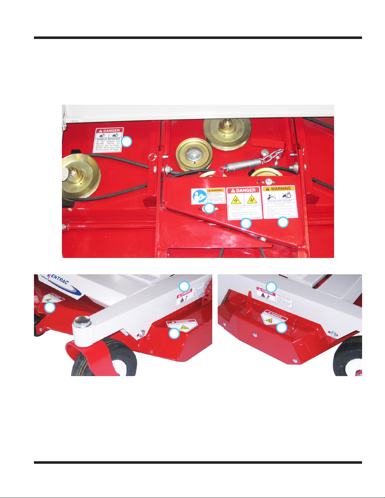
Safety Decals .........................................................................................................................................7
Training Required...................................................................................................................................9
Personal Protective Equipment Requirements ......................................................................................9
Operation Safety ....................................................................................................................................9
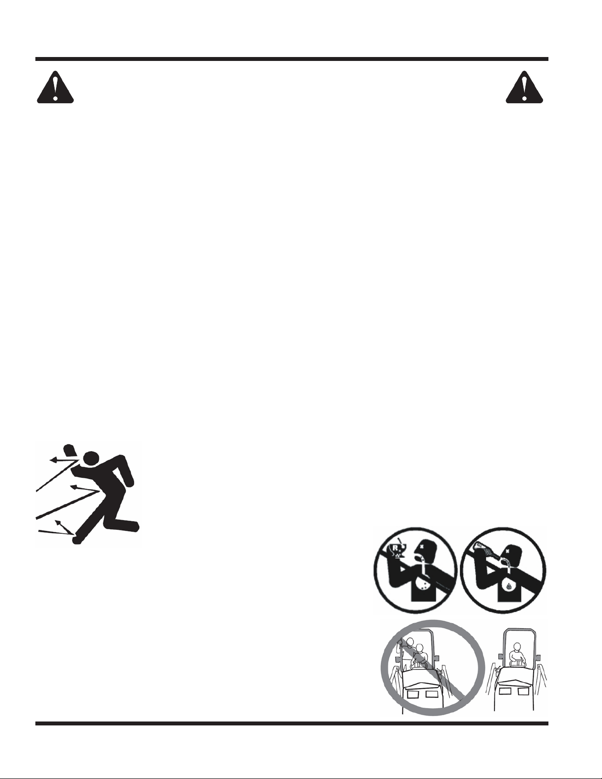
Preventing Accidents............................................................................................................................10
Keep Riders Off....................................................................................................................................10
Operating On Slopes............................................................................................................................ 11
Roadway Safety................................................................................................................................... 11
Truck Or Trailer Transport .................................................................................................................... 11
Maintenance.........................................................................................................................................12
Fuel Safety...........................................................................................................................................12
Hydraulic Safety ...................................................................................................................................13
Cutting Unit Safety ...............................................................................................................................14
OPERATIONAL CONTROLS PAGE 15
Operational Control Locations..............................................................................................................15
Main Belt Tensioner (A)........................................................................................................................15
Height Adjustment Handle (B)..............................................................................................................15
GENERAL OPERATION PAGE 16
Daily Inspection....................................................................................................................................16
Attaching ..............................................................................................................................................16
Detaching.............................................................................................................................................16
Mowing and Operating Procedure .......................................................................................................16
Transport of Mower ..............................................................................................................................17
Cutting Height Adjustment....................................................................................................................17
SERVICE PAGE 18
Cleaning and General Maintenance.....................................................................................................18
Deck Flip-Up Procedure (Service Position)..........................................................................................18
Mower Blade Removal & Installation ...................................................................................................18
Sharpening Blades...............................................................................................................................18
Belt Inspection......................................................................................................................................18
Deck Belt Replacement........................................................................................................................19
Tire Pressure........................................................................................................................................19
Deck Leveling Procedure.....................................................................................................................19
Lubrication Locations ...........................................................................................................................20
Storage.................................................................................................................................................20
Maintenance Schedule.........................................................................................................................21
Maintenance Checklist.........................................................................................................................21

TABLE OF CONTENTS
4
SPECIFICATIONS PAGE 22
Dimensions ..........................................................................................................................................22
Features...............................................................................................................................................22
Noise Emissions...................................................................................................................................23
EC Declaration of Conformity...............................................................................................................23
PARTS PAGE 24
Main Deck ............................................................................................................................................24
Carrier Frame.......................................................................................................................................26
Front Caster Wheels & Rear Roller......................................................................................................28
Hitch Assembly.....................................................................................................................................30
Spindles & Blades................................................................................................................................32
WARRANTY PAGE 34

Introduction - 5
INTRODUCTIONINTRODUCTION
Product Description
The LM600 mower is designed for the sole purpose of nish mowing and is built to give you maximum
performance and productivity. A rugged all steel reinforced carrier frame incorporates a full length rear roller
that maximizes grass striping of this ground oating deck.
The LM600 features a 60 inch (152 cm) cutting width. Ventrac’s LAS (Linear Adjustment System) provides
cutting height selections from 1-1/2” (3.8 cm) and 3-3/4” (9.5 cm). A single handle with a slight outward
pull allows for a quick and easy change in cutting height selection. A slide release allows the handle to be
returned to deck level, preventing it from catching on low branches and shrubs.
With the removal of two pins beneath the cross frame, the deck can be easily tilted to a near vertical posi-
tion for cleaning, maintenance, or storage.
Why Do I Need an Operator’s Manual?
This manual has been created to help you gain the important knowledge of what is needed to safely
operate, maintain, and service your machine. It is divided into sections for convenient reference of the
appropriate section.
You must read and understand the operator’s manual for each piece of Ventrac equipment you own. Read-
ing the operator’s manual will help you become familiar with each specic piece of equipment. Under-
standing the operator’s manual will help you, as well as others, avoid personal injury and/or damage to the
equipment. Keep this manual with the machine at all times. The manual should remain with the machine
even if it is sold. If this manual becomes damaged or unreadable, it should be replaced immediately. Con-
tact your local Ventrac dealer for a replacement.
When using a Ventrac attachment, be sure to read and follow the safety and operating instructions of both
the power unit and the attachment being used to ensure the safest operation possible.
The information in this manual provides the operator with the safest procedures to operate the machine
while getting the maximum use out of the unit. Failure to follow the safety precautions listed in this manual
may result in personal injury and/or damage to the equipment.
Venture Products Inc. is pleased to provide you with your new
Ventrac mower! We hope that Ventrac equipment will provide
you with a ONE Tractor Solution.

INTRODUCTION
Introduction - 6
Using Your Manual
Throughout this manual, you will encounter special messages and symbols that identify potential safety
concerns to help you as well as others avoid personal injury or damage to the equipment.
ATTENTION
This symbol identies potential health and
safety hazards. It marks safety precautions.
Your safety and the safety of others is involved.
SYMBOL DEFINITIONS
There are three signal words that describe the level of safety concern: Danger, Warning, and Caution.
Safety should always be the #1 priority when working on or operating equipment. Accidents are more likely
to occur when proper operating procedures are not followed or inexperienced operators are involved.
Note: Right-Hand and Left-Hand orientations may be referred to at different places throughout this manual.
Right-Hand and Left-Hand is determined as if sitting on the power unit seat facing forward.
SIGNAL WORD DEFINITIONS
Indicates a potentially hazardous situation
which, if not avoided, could result in death or
serious injury.
Indicates an imminently hazardous situation
which, if not avoided, will result in death or
serious injury. This signal word is limited to the
most extreme cases.
Indicates a potentially hazardous situation
which, if not avoided, may result in minor or
moderate injury and/or property damage. It may
also be used to alert against unsafe practices.
Manual Glossary
Power Unit A Ventrac tractor or other Ventrac engine powered device that may be operated by itself or
with an attachment or accessory.
Attachment A piece of Ventrac equipment that requires a Power Unit for operation.
Accessory A device that attaches to a Power Unit or Attachment to extend its capabilities.
Machine Describes any “Attachment” or “Accessory” that is used in conjunction with a power unit.

SAFETY
Safety - 7
SAFETY
Safety Decals
The following safety decals must be maintained on your LM600 mower.
Keep all safety decals legible. Remove all grease, dirt, and debris from safety decals and instructional
labels. If any decals are faded, illegible, or missing, contact your dealer promptly for replacements.
When new components are installed, be sure that current safety decals are afxed to the replacement
components.
A
B
C
E
D
D
F
D
F

SAFETY
Safety - 8
General Safety Procedures
for Ventrac Power Units, Attachments, & Accessories
Decal Description Part Number Quantity
A Danger, Shield Missing 00.0062 1
B Warning, Moving Part Hazard 00.0101 1
C Danger, Pinching Hazard 00.0102 1
D Danger, Keep Hands & Feet Clear 00.0123 3
E Warning, Read Owner’s Manual 00.0217 1
F Danger, Thrown Object Hazard 00.0265 2
AB C
D E
F

SAFETY
Safety - 9
General Safety Procedures
for Ventrac Power Units, Attachments, & Accessories
Training Required
• The owner of this machine is solely responsible for properly training the operators.
• The owner/operator is solely responsible for the operation of this
machine and prevention of accidents or injuries occurring to him/her-
self, other people, or property.
• Do not allow operation or service by children or untrained personnel.
Local regulations may restrict the age of the operator.
• Before operating this machine, read the operator’s manual and under-
stand its contents.
• If the operator of the machine cannot understand this manual, then it
is the responsibility of this machine’s owner to fully explain the material
within this manual to the operator.
• Learn and understand the use of all controls.
• Know how to stop the power unit and all attachments quickly in the event of an emergency.
Personal Protective Equipment Requirements
It is the responsibility of the owner to be sure that the operators use the proper personal protective equip-
ment while operating the machine. Required personal protective equipment includes, but is not limited to,
the following list.
• Wear a certied ear protection device to prevent loss of hearing.
• Prevent eye injury by wearing safety glasses while operating the machine.
• Closed toe shoes must be worn at all times.
• Long pants must be worn at all times.
• When operating in dusty conditions, it is recommended that a dust mask be worn.
Operation Safety
• Inspect machine before operation. Repair or replace any damaged, worn, or missing parts. Be sure
guards and shields are in proper working condition and are secured in place. Make all necessary
adjustments before operating machine.
• Some pictures in this manual may show shields or covers opened or removed in order to clearly illustrate
any instructions. Under no circumstance should the machine be operated without these devices in place.
• Alterations or modications to this machine can reduce safety and could cause damage to the machine.
Do not alter safety devices or operate with shields or covers removed.
• Before each use, verify that all controls function properly and inspect all safety devices. Do not operate
if controls or safety devices are not in proper working condition.
• Check parking brake function before operating. Repair or adjust parking brake if necessary.
• Observe and follow all safety decals.
• All controls are to be operated from the operator’s seat only.
• Always wear a seat belt if the machine has a roll cage/bar installed and in upright position.
• Ensure the attachment or accessory is locked or fastened securely to the power unit before operating.
• Ensure that all bystanders are clear of the power unit and attachment before operating. Stop machine if
someone enters your work area.
• Always be alert to what is happening around you, but do not lose focus on the task you are performing.
Always look in the direction the machine is moving.
• Look behind and down before backing up to be sure of a clear path.
• If you hit an object, stop and inspect the machine. Make all necessary repairs before operating machine again.
• Stop operation immediately at any sign of equipment failure. An unusual noise can be a warning of equipment
failure or a sign that maintenance is required. Make all necessary repairs before operating machine again.

SAFETY
Safety - 10
General Safety Procedures
for Ventrac Power Units, Attachments, & Accessories
• If equipped with a high/low range feature, never shift between high and low range while on a slope.
Always move the machine to level ground and engage the parking brake before shifting range.
• Do not leave machine unattended while it is running.
• Always park the machine on level ground.
• Always shut off engine when connecting attachment drive belt to the power unit.
• Never leave the operator’s seat without lowering the attachment to the ground, setting the parking
brake, shutting off the engine, and removing the ignition key. Make sure all moving parts have come to
a complete stop before dismounting.
• Never leave equipment unattended without lowering the attachment to the ground, setting the parking
brake, shutting off the engine, and removing the ignition key.
• Only operate in well-lit conditions.
• Do not operate when there is a risk of lightning.
• Never direct the discharge of any attachment in the direction of people, buildings, animals, vehicles, or
other objects of value.
• Never discharge material against a wall or obstruction. Material may ricochet back towards the operator.
• Use extra caution when approaching blind corners, shrubs, trees, or other objects that may obscure vision.
• Do not run the engine in a building without adequate ventilation.
• Do not touch the engine or the mufer while the engine is running or immediately after stopping the engine.
These areas may be hot enough to cause a burn.
• Do not change the engine governor settings or over-speed the engine. Operating engine at excessive speed
may increase the hazard of personal injury.
• To reduce the hazard of re, keep the battery compartment, engine, and mufer areas free of grass, leaves,
and excessive grease.
Preventing Accidents
• Clear working area of objects that might be hit or thrown from machine.
• Keep people and pets out of mowing area.
• Know the work area well before operation. Do not operate where traction or
stability is questionable.
• Reduce speed when you are operating over rough ground.
• Equipment can cause serious injury and/or death when improperly used.
Before operating, know and understand
the operation and safety of the power
unit and the attachment being used.
• Do not operate machine if you are not in good physical and
mental health, if you will be distracted by personal devices, or are
under the inuence of any substance which might impair deci-
sion, dexterity, or judgment.
• Children are attracted to machine activity. Be aware of children
and do not allow them in the working area. Turn off the machine if
a child enters the work area.
Keep Riders Off
• Only allow the operator on the power unit. Keep riders off.
• Never allow riders on any attachment or accessory.

SAFETY
Safety - 11
General Safety Procedures
for Ventrac Power Units, Attachments, & Accessories
Operating On Slopes
• Slopes can cause loss-of-control and
tip-over accidents, which can result in
severe injury or death. Be familiar with the
emergency parking brake, along with the
power unit controls and their functions.
• If power unit is equipped with a fold down
roll bar, it must be locked in the upright
position when operating on any slope.
• Use low range (if equipped) when operating
on slopes greater than 15 degrees.
• Do not stop or start suddenly when operating on slopes.
• Never shift between high and low range while on a slope. Always move the power unit to level ground
and engage the parking brake before shifting range or placing the power unit in neutral.
• Variables such as wet surface and loose ground will reduce the degree of safety. Do not drive where
machine could lose traction or tip over.
• Keep alert for hidden hazards in the terrain.
• Stay away from drop-offs, ditches, and embankments.
• Sharp turns should be avoided when operating on slopes.
• Pulling loads on hills decreases safety. It is the responsibility of the owner/operator to determine loads
that can safely be controlled on slopes.
• Transport machine with attachment lowered or close to the ground to improve stability.
• While operating on slopes, drive in an up and down direction when possible. If turning is necessary
while driving across slopes, reduce speed and turn slowly in the downhill direction.
• Assure a sufcient supply of fuel for continuous operation. A minimum of one-half tank of fuel is recommended.
Roadway Safety
• Operate with safety lights when operating on or near roadways.
• Obey all state and local laws concerning operation on roadways.
• Slow down and be careful of trafc when operating near or crossing roadways. Stop before crossing
roads or sidewalks. Use care when approaching areas or objects that may obscure vision.
• If there is doubt of safety conditions, discontinue machine operation until a time when
operation can be performed safely.
• When operating near or on roadways, have a Slow Moving Vehicle Emblem clearly
displayed.
Truck Or Trailer Transport
• Use care when loading or unloading machine into a truck or trailer.
• Use full width ramps for loading machine into a truck or trailer.
• The parking brake is not sufcient to lock the machine during transport. Always secure the power unit
and/or attachment to the transporting vehicle securely using straps, chains, cable, or ropes. Both front
and rear straps should be directed down and outward from the machine.
• Shut off fuel supply to power unit during transport on truck or trailer.
• If equipped, turn the battery disconnect switch to the Off position to shut off electrical power.

SAFETY
Safety - 12
General Safety Procedures
for Ventrac Power Units, Attachments, & Accessories
Maintenance
• Keep all safety decals legible. Remove all grease dirt, and debris from safety decals and instructional labels.
• If any decals are faded, illegible, or missing, contact your dealer promptly for replacements.
• When new components are installed, be sure that current safety decals are afxed to the replacement
components.
• If any component requires replacement, use only original Ventrac replacement parts.
• Always turn the battery disconnect to the Off position or disconnect the battery before performing any
repairs. Disconnect the negative terminal rst and the positive terminal last. Reconnect the positive
terminal rst and the negative terminal last.
• Keep all bolts, nuts, screws, and other fasteners properly tightened.
• Always lower the attachment to the ground, engage parking brake, shut off engine, and remove the
ignition key. Make sure all moving parts have come to a complete stop before cleaning, inspection,
adjusting or repairing.
• If the power unit, attachment, or accessory requires repairs or adjustments not instructed in the operator’s
manual, the power unit, attachment, or accessory must be taken to an authorized Ventrac dealer for service.
• Never perform maintenance on the power unit and/or attachment if someone is sitting in the operator’s seat.
• Always use protective glasses when handling the battery.
• Check all fuel lines for tightness and wear on a regular basis. Tighten or repair them as needed.
• To reduce the hazard of re, keep the battery compartment, engine, and mufer areas free of grass,
leaves, and excessive grease.
• Do not touch the engine, the mufer, or other exhaust components while the engine is running or imme-
diately after stopping the engine. These areas may be hot enough to cause a burn.
• Allow the engine to cool before storing and do not store near an open ame.
• Do not change the engine governor settings or over-speed the engine. Operating engine at excessive
speed may increase the hazard of personal injury.
• Springs may contain stored energy. Use caution when disengaging or removing springs and/or spring
loaded components.
• An obstruction or blockage in a drive system or moving/rotating parts may cause a buildup of stored
energy. When the obstruction or blockage is removed, the drive system or moving/rotating parts may
move suddenly. Do not attempt to remove an obstruction or blockage with your hands. Keep hands,
feet, and clothing away from all power-driven parts.
• Dispose of all uids in accordance with local laws.
Fuel Safety
• To avoid personal injury or property damage, use extreme care in handling gasoline. Gaso-
line is extremely ammable and the vapors are explosive.
• Do not refuel machine while smoking or at a location near ames or sparks.
• Always refuel the machine outdoors.
• Do not store machine or fuel container indoors where fumes or fuel can reach an open
ame, spark, or pilot light.
• Only store fuel in an approved container. Keep out of reach of children.
• Never ll containers inside a vehicle or on a truck or trailer bed with a plastic liner. Always place containers
on the ground away from your vehicle before lling.
• Remove machine from the truck or trailer and refuel it on the ground. If this is not possible, refuel the
machine using a portable container, rather than from a fuel dispenser nozzle.
• Never remove fuel cap or add fuel with the engine running. Allow engine to cool before refueling.
• Never remove fuel cap while on a slope. Only remove when parked on a level surface.
• Replace all fuel tank and container caps securely.

SAFETY
Safety - 13
General Safety Procedures
for Ventrac Power Units, Attachments, & Accessories
• Do not overll fuel tank. Only ll to bottom of fuel neck, do not ll fuel neck full. Overlling of fuel tank could
result in engine ooding, fuel leakage from the tank, and/or damage to the emissions control system.
• If fuel is spilled, do not attempt to start the engine. Move the power unit away from the fuel spill and
avoid creating any source of ignition until fuel vapors have dissipated.
• If the fuel tank must be drained, it should be drained outdoors into an approved container.
• Dispose of all uids in accordance with local laws.
• Check all fuel lines for tightness and wear on a regular basis. Tighten or repair them as needed.
• The fuel system is equipped with a shut-off valve. Shut off the fuel when transporting the machine to
and from the job, when parking the machine indoors, or when servicing the fuel system.
Hydraulic Safety
• Make sure all hydraulic connections are tight and all hydraulic hoses and tubes are in good condition.
Repair any leaks and replace any damaged or deteriorated hoses or tubes before starting the machine.
• Hydraulic leaks can occur under high pressure. Hydraulic leaks require special care and attention.
• Use a piece of cardboard and a magnifying glass to locate sus-
pected hydraulic leaks.
• Keep body and hands away from pinhole leaks
or nozzles that eject high pressure hydraulic uid.
Hydraulic uid escaping under high pressure can
penetrate the skin causing serious injury, leading to
severe complications and/or secondary infections
if left untreated. If hydraulic uid is injected into the
skin, seek immediate medical attention no matter
how minor the injury appears.
• Hydraulic system may contain stored energy. Before performing maintenance or repairs on the hydraulic
system, remove attachments, engage parking brake, disengage weight transfer system (if equipped), shut
off engine, and remove ignition key. To relieve pressure on the auxiliary hydraulic system, shut off the power
unit engine and move the secondary S.D.L.A. lever left and right before disconnecting the auxiliary hydraulic
quick couplers.
• Dispose of all uids in accordance with local laws.
Fuel Safety (continued)

SAFETY
Safety - 14
LM600 Safety Procedures
Cutting Unit Safety
• Rotating Blades: Contact with the rotating mower blades or other moving parts may cause
personal injury. Keep hands and feet away.
• Rotation of one blade may cause another blade to rotate.
• Thrown Object Hazard: Do not point discharge toward people, animals, or buildings when
operating. Never operate with the deectors removed.
• When not mowing, always shut off the PTO to stop the mower blades.
• Never raise the mower deck with the blades running.

Operation - 15
OPERATIONAL CONTROLSOPERATIONAL CONTROLS
Operational Control Locations
Use the following images to help identify the locations
of operational controls. The letter next to each control
can be referenced to the list that follows these images.
A
B
A - Main Belt Tensioner
B - Height Adjustment Handle
Main Belt Tensioner (A)
Release
tension
Apply
tension
Rotating the main belt tensioner clockwise until it
locks applies tension to the attachment drive belt.
Rotating the main belt tensioner counter-clockwise
releases tension on the attachment drive belt, allow-
ing the operator to remove or install the attachment
drive belt onto the power unit.
Height Adjustment Handle (B)
The height adjustment handle is used to raise or
lower the deck to achieve the desired cutting height.

Operation - 16
GENERAL OPERATIONGENERAL OPERATION
* Refer to power unit operator’s manual for operation of
power unit controls.
Daily Inspection
1.
Always set the parking brake, shut off power
unit engine, remove the ignition key, and ensure
all moving parts have come to a complete stop
before inspecting components, or attempting
any repair or adjustment.
Park machine on a level surface, with the engine
shut off and all uids cold.
2. Perform a visual inspection of both the power
unit and the mower deck. Look for loose or
missing hardware, damaged components, or
signs of wear.
3. Inspect the drive belts and mower blades. Belts
should be in good condition. Blades should be
sharp and securely fastened. Service as required.
4. Refer to the power unit operator’s manual.
Check the power unit’s engine oil, hydraulic oil,
cooling system, tire pressure, and fuel level. Add
uid or service as required.
5. Test the power unit’s operator safety interlock
system*.
Attaching
1. Drive the power unit slowly forward into the hitch
arms of the mower deck. Align the lift arms of
the power unit with the mower hitch arms by
raising or lowering the front hitch and complete
the engagement.
2. Once completely engaged, close the front hitch
locking lever.*
3. Engage the parking brake* and shut off the
engine.
4. Place the attachment belt onto the PTO drive
pulley on the power unit. Ensure the belt is prop-
erly seated in each pulley.
5. Engage the main belt tensioner. NOTE: if deck
is raised to the top position, the deck shield will
interfere with the belt tensioner.
6. Always check to ensure the deck belt is properly
located in each pulley groove before attempting
to operate.
Detaching
1. Park the power unit on a level surface and set
the parking brake.*
2. Lower the mower deck to the ground.
3. Shut off power unit engine.
4. Raise the mower deck to the highest cutting
height position for easy reattachment.
5. Disengage the main belt tensioner.
6. Remove the attachment belt from the PTO drive
pulley of the power unit.
7. Disengage the hitch locking lever.*
8. Restart the power unit and slowly back away
from the mower. A side to side movement of the
steering wheel may aid disengagement.
Mowing and Operating Procedure
Before operation, perform daily inspection and con-
rm that the cutting height is set properly. Set the
power unit’s weight transfer system* (if equipped) to
the desired setting.
With the power unit engine running between 2,000
and 2,500 RPM, engage the PTO switch. Adjust the
throttle to the desired engine RPM.
Lower the mower deck to the ground and place
the power unit’s primary S.D.L.A. control lever in
the oat position by pushing it to the right until the
detent engages. The lever will stay in this position
until intentionally removed.
Begin forward motion in the desired path of mowing.
Avoid obstacles, removing debris as necessary.
A stripe pattern in the grass is produced when each
mowing pass is done in the opposite direction of
the pass beside it. This look is enhanced by the
full length roller, which helps to roll the grass in the
direction of travel.
Lift the mower deck when the edge of the mowing
area is reached. Turn the power unit and mower
around and align for the next pass.
Always shut off the engine, remove the ignition
key, and set the parking brake before checking
mower deck or blade condition, or attempting
any repair or adjustment.
Blades should be kept in good condition. Sharp
blades will increase efciency and improve the
quality of cut.

GENERAL OPERATION
Operation - 17
Wet grass has a tendency to build up under the
deck. Periodic checking should be done by the
operator to determine if the deck should be cleaned.
The deck should also be checked anytime mowing
performance seems to be reduced.
Mulching procedures may vary greatly due to cli-
mate, type of grass, and soil conditions. It is gener-
ally best to mow frequently and in dry conditions.
Leaves are usually mulched and dispersed better
when some grass is cut with the leaves.
Transport of Mower
Transport the mower deck with the power unit front
hitch and mower fully raised to reduce wear of the
equipment. Travel slowly when transporting over
undulating and rough surfaces to maintain control
of power unit and to reduce the shock to the power
unit and mower deck. Always disengage the power
unit PTO before transporting the mower.
Cutting Height Adjustment
1.
Always shut off the engine, remove the ignition
key, and set the parking brake before checking
mower deck or blade condition, or attempting
any repair or adjustment.
Lift the height adjustment handle upward and
hook the lock pin into the notch (A) on the height
setting control bracket.
2.
A
B
Pull the handle outward to release the catch
from the height adjust selector plate (B).
3. Rotate the height adjustment handle up or down
until the desired setting is reached.
4. When the desired cutting height is reached,
release the height adjustment tab into the proper
slot on the selector plate.
5. Lift the height adjustment handle free of the
height setting control bracket and rotate down to
lay on the deck.

Service - 18
SERVICESERVICE
Cleaning and General Maintenance
For best results, and to maintain the nish of the
mower, clean or wash the mower to remove accu-
mulated clippings, leaves, and dirt when the job is
nished. Refer to the “Deck Flip-up procedure” in the
service section to access the underside of the deck.
If washing the deck, do not spray directly into bear-
ings or seals. After washing, it is important to run the
mower so that water does not reside on seals of bear-
ings for the drive system. When washing is complete,
return the deck to the operating position and activate
the PTO for 30 seconds to remove any standing water.
Deck Flip-Up Procedure (Service Position)
1. Park the power unit and mower deck on a
smooth, level surface.
2. Raise the power unit front hitch to its highest
position.
3. Set the parking brake, shut off the engine, and
remove the ignition key.
4. Adjust the mower deck height to the lowest cut-
ting height position.
5. Lift the mower deck shield and remove the 2) ball
pins (A) that lock the hitch arms from pivoting.
A A
6. Lift the mower deck up to a near vertical position
and reinstall the ball pins to lock the deck in the
upright position.
7. To return the deck to the operating position,
remove the 2) ball pins and lower the deck to
the ground. Reinstall the ball pins and lower the
mower deck shield into place.
Mower Blade Removal & Installation
1.
Mower blades may be sharp. Always wear
safety glasses, leather gloves, and a long
sleeve shirt when working with mower blades.
Rotate the mower deck up to the service posi-
tion following the deck ip-up procedure.
2. Place a short piece of 2 x 4 wood between the
end of the blade and an appropriate structural
part of the underside of the deck to prevent the
blade from rotating.
3. Loosen the blade bolt counterclockwise and
remove the blade for sharpening or replace-
ment.
4. When installing a blade, the wood block must be
placed on the opposite side to prevent rotation
for tightening the blade bolt.
5. Tighten the blade bolt to 75-80 ft. lbs.
Sharpening Blades
Blades should be sharpened and balanced by a pro-
fessional. Maintain balance, same bevel, and length
of sharpened surface.
Belt Inspection
Inspecting the drive belts of the mower can prevent
sudden belt failure by nding problems before they
cause a belt to break.
Typical wear
on a drive
belt may
result in the
conditions
shown in the
diagram. If
any of these
conditions
occur, the drive belt will require replacement.
Always set the parking brake, shut off power
unit engine, remove the ignition key, and ensure
all moving parts have come to a complete stop
before inspecting components or attempting any
repair or adjustment.
Attention
If any component requires replacement, use only
original Ventrac replacement parts.

SERVICE
Service - 19
Deck Belt Replacement
1. Detach the mower deck from the power unit.
2. Raise the mower deck shield.
3. Remove the old deck belt.
4. Install the new deck belt. Place belt into the pul-
ley system according to the belt diagram located
on the underside of the mower deck shield.
5. Ensure the belt is engaged in the groove of
each spindle pulley and around each of the at
idler pulleys.
Tire Pressure
The mower deck is equipped with at-free, cushioning
tires to provide a maintenance free, consistent cutting
height. No tire pressure adjustments are required.
Deck Leveling Procedure
1.
Mower blades may be sharp. Always wear
safety glasses, leather gloves, and a long
sleeve shirt when working with mower blades.
Place the mower on a hard surface that is clean
and level. Detach the mower from the power unit.
2. Raise the mower deck to the highest cutting
height setting.
3. Block the tires and rear roller to prevent the
mower from rolling during leveling procedure.
Place blocks under 4) corners of the deck when
reaching under the mower deck to prevent the
deck from accidentally dropping and trapping or
crushing a bodily appendage.
4. Check the mower blades to ensure they are not
bent. To check for bent blades, move one blade
tip to the back of the deck and measure from
the oor to the blade. Rotate the other blade tip
to the back of the deck and measure again. If
the distance is different, the blade is bent and
should be replaced before continuing.
5. Go to one side of the deck. Turn the blade so
the tip is at the back of the deck. Measure the
distance from the oor to the blade.
6.
A
Move to the other side of the mower deck and
turn that blade tip to the
back of the deck. If this
measures differently from
the rst side, adjust the
threaded rod linkage (A)
directly above on the top
side of the deck until the
measurement is the same
as the rst side.
7. Once the deck has been leveled side to side,
rotate the same blade tip to the front of the deck
and measure. The distance from the oor to the
blade should be the same to 1/8” (3 mm) lower
than the rear measurement.
8. If the front of the deck requires adjustment, loosen
B
the cross bolts (B) in the
carrier frame. Move the
bolts forward in the slots
to lower the deck or move
the bolts rearward in the
slots to raise the deck.
NOTE: slight movement
of the bolt in the front
carrier slots will make a signicant difference in the
front deck height.

SERVICE
Service - 20
Lubrication Locations
Lubrication is required at the following locations using
a lithium complex NLGI #2 type grease. Refer to the
maintenance schedule for service intervals and
amount of grease.
Rear Roller Bearings
Carrier Wheel Pivot & Wheel Axle Bearing
Mower Spindles
Storage
Preparing the Mower for Storage
1. Clean the mower deck and frame.
2. Inspect for loose or missing hardware, damaged
components, or signs of wear. Repair or replace
any damaged or worn components.
3. Inspect belts, spindles, and blades. Repair or
replace any damaged or worn components.
4. Inspect safety decals. Replace any safety decals
that are faded, illegible, or missing.
5. Apply grease to all grease points.
6. Wipe off all excess grease or oil.
Removing the Mower from Storage
Inspect, clean, and prepare the mower for use.
Other manuals for LM600
1
Table of contents
Other Ventrac Lawn Mower manuals

Ventrac
Ventrac Ventrac HQ680 User manual

Ventrac
Ventrac 4100 Series Owner's manual

Ventrac
Ventrac MJ840 User manual

Ventrac
Ventrac MY560 User manual

Ventrac
Ventrac LM600 Setup guide

Ventrac
Ventrac HM600 User manual

Ventrac
Ventrac HM602 User manual

Ventrac
Ventrac Ventrac HQ680 Owner's manual

Ventrac
Ventrac MJ840 User manual

Ventrac
Ventrac MK960 User manual
Popular Lawn Mower manuals by other brands

Stiga
Stiga Park series Workshop manual

Craftsman
Craftsman 917.374943 Owner's installation guide

Gude
Gude HIGH WHEELER ST 460 Translation of the original instructions

Toro
Toro 74944 Operator's manual

Craftsman
Craftsman 247.203723 Operator's manual

Craftsman
Craftsman 28910 - Lt 2000 20 HP 42" Lawn Tractor Operation manual