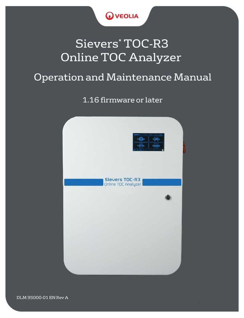
Veolia Sievers TOC-R3 User manual

© 2023 Veolia All Rights Reserved. Sievers TOC-R3 Analyzer Installation Guide DQS 95000-01 EN Rev. A
*Sievers is a trademark of Veolia and may be registered in one or more countries.
1
Installation Instructions
Customer Requirements:
Before starting the installation, ensure the following
items are acquired.
• Carrier Gas; COconcentration < 1 ppm,
Hydrocarbon concentration in the air < 0.1 ppm,
Moisture free and particle free.
Important!
See the “Warnings” section for additional important
information.
Secure all gas cylinders to an immovable
structure or permanent wall. Wear eye protection
when using compressed gases to avoid possible eye
injury. Only use regulators designed for use with the
selected gas. Store compressed gases in accordance
with all safety codes.
Sample Line pressure must not exceed 20 kPa (0.2
Bar, 2.9 psig).
To ensure proper operation and protect against injury,
do not operate the Analyzer with the covers o or
the door open.
A qualied Electrician must perform all electrical
installation activities.
All drain tubing and the vented drain must be
positioned lower than the level of the Analyzer to
minimize back pressure on the drain lines.
Always use ESD protection while working inside
the Analyzer and any Optional Accessories.
When handling components that contain sample,
standards, waste solution, or reagents, always wear
eye protection and gloves.
Always follow the manufacturer’s instructions
and SDS guidelines for preparation, handling,
and disposal of all standards, reagents, and
consumables.
Cautions
Save the original packing materials. If for any
reason you need to return the Analyzer, you MUST
pack the instrument in the original carton to ensure
that no damage occurs during shipment.
Use a 2-person lift. This instrument weighs over
18 kg (40 lb). It is the policy of OSHA and Veolia to
require a 2-person lift for items weighing over 18 kg
(40 lb).
Sievers* TOC-R3
Online TOC Analyzer
Installation Guide
Important!
Access the Operation and Maintenance Manual (referred
to as “Manual”) from www.sieversinstruments.com
[Customer Support > Sievers Analyzers & Instruments].
English
SIEVERSTOC-R3
OnlineTOCAnalyzer
• Options: Nitrogen, Zero/Synthetic Air, or Plant
Instrument Air (ANSI 7.0.01), Air Box Accessory.
• Pressure: 100-200 kPa (1-2 Bar, 14.5-29 psig)
• Flow Rate: 30-50 LPH
• Carboy (2 L, 0.55 US gal); for Acid
• Acid; Method dependent, use one of the following:
• 1-3% HCl (NPOC Mode)
• 1-3% HPO
• Small Funnel; 1 cm wide at smallest
•
• Tubing Cutter
• Ethernet Cable; optional.
If using Nitrogen or Zero/Synthetic Air
• Carrier Gas Tubing; 6 mm OD, 4 mm ID
If using Plant Instrument Air or Air Box Accessory
• Soda Lime; 700 g
• Granulated, 2-4 mm with indicator as CO
remover.
If using Dilution Water Feature, Optional
• Carboy (19 L, 5 US gal); for Dilution Water
• Dilution Water; DI Water or better, low TOC < 1
ppm
Additional Customer Requirements before
installation:
• If using an external air connection, there must be
an appropriate Pressure Regulator [Maximum of
installed near the Analyzer location.
• Each Sample Point (up to two) must have an
• The Analyzer must be installed within 2 m (6.6 ft.)
of the Sample Point(s).
• Veolia recommends that the Analyzer be connected
to an external switch or circuit breaker near the
Analyzer.
Analyzer Dimensions Weight:
Height: 900 mm
(35.5 in)
55 kg
(121.3 lb)
Width: 644.3 mm
(25.4 in)
Use a 2-person
lift!
Depth: 354.5 mm
(13.9 in)

2
© 2023 Veolia. All Rights Reserved. Sievers TOC-R3 Analyzer Installation Guide DQS 95000-01 EN Rev. A
*Sievers is a trademark of Veolia and may be registered in one or more countries.
Operating Specifications
Analysis Modes TC, NPOC, TNb, TOCdiff, POC/VOC, TIC
Ranges NPOC/TOCdiff : 0-10; 0-200; 0-2,000; 0-10,000 with Dilution to 50,000 ppm;
TOC Wide Range: 0-200 and 200-20,000;
TNb : 0-150 and 0-1,500 ppm; POC/VOC: 0-25 ppm;
Options/Accessories Leak detection, Sample Stream 2, Particulate Sampler, Air Box, Communication
Box, Mounting Rack
Features Auto Calibration, Dilution, Check Function, Auto Rinse, Connectivity
(Remote Control), Predictive Maintenance
Precision +/-2% End of detector range†
Linearity R² ≥0.997†
LOD <1 ppm†
Analysis Time 3-5 min typically
Smallest Inner Diameter (ID) 2 mm smallest tubing diameter
Salt Tolerance 3-5% NaCl
Carrier Gas CO2 free air < 1 ppm CO2 and < 0.1 ppm hydrocarbon: 100-200 kPa
@ 30-50 L/hr flow rate (Optional: Air Box)
Sample Temperature 2-60 °C (35.6-150 °F)
Ambient Temperature 2-40 °C (35.6-104 °F)
Minimum Sample Flow Rate 100 mL/min without Particulate Sampler or 11.7-50 LPM (3.1-13.2 US gal/min)
with Particulate Sampler
Drain Gravity, No back pressure
Analyzer Specifications
Communication Protocols OPC-UA, Modbus TCP/IP
Inputs Digital Input (4)
Display 7 in. Touch panel
Power AC 110-230 V ±10 V, 50/60 Hz, 400-600 VA
Outputs Ethernet, 4-20 mA (6), Programmable Digital Relay (4)
Installation/Overvoltage Category II
Available Configurations Single-Stream or Two-Stream (Optional)
Dimensions 900 H x 644.3 W x 354.5 D mm (35.5 H x 25.4 W x 14 D in)
Weight 55 kg (121 lb)
Safety Certifications CE, UL, CSA
Regulatory DIN EN 1484 /ISO 8245, EPA 415.3, SM 5310B, ASTM D5173, HJ 501,
DIN EN 12260
Environment
Enclosure Standard: IP-54, Option: ATEX Zone 1 & 2 T4, IECEx Zone 1 & 2 T4, C1D2
Maximum Relative Humidity Up to 85%, non-condensing
†Stated analytical performance achieved under ideal laboratory conditions.
System Specications

3
© 2023 Veolia. All Rights Reserved. Sievers TOC-R3 Analyzer Installation Guide DQS 95000-01 EN Rev. A
*Sievers is a trademark of Veolia and may be registered in one or more countries.
Step 1: Unpack and Inspect the Analyzer
• Carefully remove any shipping materials from the
exterior and interior of Analyzer.
• Locate the Shipping Kit inside the Analyzer. Be
careful when handling! Several items are fragile!
• Verify that all items were received. See "Table 3.
Shipping List" on page 9. All references to
the [Shipping List] items are shown in [brackets].
For example, callout “[2]” refers to Item #2 of the
Shipping List.
• Inspect the Analyzer for any damage. If damage
has occurred during shipment, contact Technical
Support or your local service provider.
• All connections to the Analyzer will be connected
from the bottom of the enclosure. See Table 1 and
Figure 1 for the Port Names and Port Numbers.
Reference this table for all Port connections made
during installation.
Step 2: Select a location for the Analyzer
NOTE: If you have purchased the optional Mounting
Rack, refer to the Mounting Rack Installation
Instructions.
The Analyzer is designed to be mounted indoors on
an wall or support stand. For proper heat dissipation
and humidity control, ensure that 30.5 cm (12 in) is
available at the top and both sides of the Analyzer.
Allow 48.3 cm (19 in) clearance in front and below
the Analyzer for access to the interior and external
connections. When selecting the location, mount the
Analyzer so that the display screen is approximately
at eye-level. Mounting the Analyzer higher could lead
to potential serviceability and safety issues. For more
information, refer to “Chapter 3: Installation” and
“Appendix A: Analyzer Dimensions” in the Manual.
Avoid direct sunlight and extreme temperatures.
Operating at elevated temperatures greater than 40
°C (104 °F) prevents proper operation, and operating
at temperatures lower than 2 °C (35.6 °F), can cause
measurement errors.
Select and procure hardware for mounting the Analyzer
on a wall (M8 (qty 4), length variable) or instrument
rack (M6x12 (qty 4)), if using optional Mounting Rack),
hardware must be able to support four times the
weight of the unit [220 kg (485 lb)]. There are four
mounting brackets on the Analyzer; two on the top and
two on the bottom. The Analyzer must be mounted in
place to remain stationary and prevent damage to the
hardware.
Step 3: Install any Optional I/O or Carrier Gas
Accessories
The Communication Box, Air Box, and/or the Air
Scrubber are all purchasable accessories. Install any
accessories near the Analyzer, either wall mounted
or attached to an instrument rack. The optional
accessories must be installed within 150 cm (59 in)
of the Analyzer due to cable and tubing lengths. Do
not allow any tubes, cables, or wires to bend sharply.
Use appropriate weight bearing mounting hardware;
either M8x20 (qty 4) if using the optional Mounting
Rack or M8 (qty 4) for mounting to the wall. If mounting
to a wall, select an appropriate screw length for the
wall condition. Power should not be connected to
the Analyzer or any Accessories yet! For more
information, consult the Manual.
•
Afterwards, install the Customer I/O wiring
connections through the bottom of the
Communication Box enclosure. For more
information, consult the Manual.
• If using, install the Air Box and Air Scrubber.
The Air Box receives 24V DC power from the
Communication Box. The Air Box power wires
must be connected to the Communication Box.
The Air Scrubber Housing must be prepared. For
more information, consult the Manual.
Table 1. Analyzer Connections (all “Port” references)
1. Enclosure Drain
2. Sample Waste Outlet (Gravity Drain)
3. Dilution / Rinsing Water
4. Acid Supply Inlet
5. Calibration, Single Measurement, and Check Standard
Inlet
6. Sample Inlet 2
7. Sample Inlet 1
8. Carrier Gas
Outlet
9. Carrier Gas Inlet
10. Ethernet Port
11. No Connection
12. Analog Channel
(12-Pin
Connection)
13. Binary/Digital
Channel (12-Pin
Connection)
14. Power Supply Cord
15. No Connection
Figure 1. Connections/Ports (view from
below)
Figure 2. Communication Box and Air Box wiring
Air Box Power Wire Bundle
Port 13Port 12
Communication
Box
Air Box

4
© 2023 Veolia. All Rights Reserved. Sievers TOC-R3 Analyzer Installation Guide DQS 95000-01 EN Rev. A
*Sievers is a trademark of Veolia and may be registered in one or more countries.
Step 3 — continued...
Connect the Air Box Power
Wires
Route the ±24 V power wires
from the top of the Air Box to
the open port on the top of the
Communication Box. See Figure
2 on page 3. Open the
Communication Box door and
gently pull in any excess cable
length into the enclosure. Do not
allow the wires to bend sharply.
Connect the wires to the power
rail inside the Communication Box
next to the I/O Terminal Block. See
Figure 3.
Prepare the Air Scrubber
Housing
1. Carefully open the bottom
knurled cap (without tubing
ports) to reveal the inside of the Air Scrubber
Housing. The central tube comes pre-installed with
an Activated Carbon Cartridge.
2. Remove the Filter Ring.
3.
4. Reinstall the Filter Ring to seal the outer tube and
contain the Soda Lime granules.
5.
6. Slot the prepared Air Scrubber Housing into the
mounting brackets so that the Inlet and Outlet
ports are oriented on top of the Housing.
Connect the Communication Box to the Analyzer
NOTE: If using the Air Box, ensure the Air Box power
wiring connections have been completed prior to
connecting the Communication Box to the Analyzer.
1. Connect the Right Cable Connector (12-pin
connector on top of the Communication Box) to
Port 13 on the bottom of the Analyzer enclosure.
2. Next, connect the Left Cable Connector (12-pin
connector on top of the Communication Box) to
Port 12 on the bottom of the Analyzer enclosure.
See Figure 2 on page 3.
NOTE: The Right Cable Connector (Port 13) carries
power to the Communication Box power rail from the
Analyzer. See Figure 2 on page 3.
Step 4: Connect the Compressed Gas Source
The Analyzer requires low-CO gas as
and Accessories purchased, the compressed gas
connection, ensure there is an appropriate Pressure
Regulator [maximum of 100 kPa (1 Bar, 14.5 psig)]
installed nearby as well a dedicated Shut-o Valve.
The Analyzer Carrier Gas Inlet (Port 9) uses 6mm
OD, 4mm ID tubing. Cut the Carrier Gas Tubing with
a tubing cutter to length for your environment and
If using Nitrogen:
Connect the Nitrogen source Carrier Gas Line to the
Analyzer Carrier Gas Inlet (Port 9).
If using Zero/Synthetic Air:
Connect the Zero/Synthetic Air source Carrier Gas
Line to the Analyzer Carrier Gas Inlet (Port 9).
If using Plant Instrument Air (ANSI/ISA 7.0.01):
1. Connect the compressed Plant Instrument Air
source to the Air Scrubber Inlet (central port on
top of Air Scrubber Housing). Both the Analyzer
and Air Scrubber connection ports use 6 mm OD
tubing.
2.
top of Air Scrubber Housing) tubing to the Analyzer
Carrier Gas Inlet (Port 9).
If using Air Box Accessory:
NOTE: The Air Box has its
own Pressure Regulator
inside the enclosure.
1. Open the Air Box door.
2. Route the Carrier Gas
Tubing into the bottom
of the Air Box enclosure
through the hole shown.
See Figure 4.
3. Install the Carrier Gas
Tubing to the Outlet (left side) of the internal
Pressure Regulator.
4. Install the other end of the Carrier Gas Tubing to
the Air Scrubber Inlet (central port on top of Air
Scrubber Housing).
5.
top of Air Scrubber Housing) Carrier Gas Tubing to
the Analyzer Carrier Gas Inlet (Port 9).
Step 5: Connect the Waste Line
Locate the Waste Tubing [18] in the Shipping Kit. See
"Table 3. Shipping List" on page 9. Important!
The Analyzer requires a gravity drain with little to
no back pressure [less than 7 kPa (0.07 Bar, 1 psig)].
1. Open the Analyzer door and
locate the Gas Cooler Unit Drain
T-Fitting in the bottom right
compartment of the Analyzer.
2. Route the Waste Tubing up into
the Analyzer through Port 2. This
Figure 5.
3. Connect the Waste Tubing [18] to
the barb on the Gas Cooler Drain
T-Fitting. Ensure that the tubing
is fully inserted on the barb. See
Figure 5 and Figure 6 on page
5.
Figure 3.
Not Used
12345678910
14 14 14 14
11 11 11 11
12 12 12 12
11 12 13 14 15
16
Option: From
Air Box Accessory,
Customer
connection.
01 02 03 04 05 06 14 15 16 17 12 13 14 15 16 17
Analog Output
(Connects to
Sensor Board)
0/4 - 20 mA Max. Load
V: 250 VAC
I: 5 A
V: 24 VAC, I: 2 A
0 - level: DC 0... 5 V
1 - level: DC 18... 30 V
Digital Output
(Connects to Digital I/O Board)
Indicates
Connection
on Circuit
Board
-24V
+24V
-24V
+24V
BLK BRN
Digital Input
Signal Strength by I/O Type
Lower terminal I/O Connections made by Customer
Upper terminal wires connected at the factory
NO NO NO NO
NC NC NC NC
Detail:
Air Box Power
Connections on
Communication Box
I/O Terminal Block
Figure 4. Air Box Carrier Gas
Tubing
Figure 5. Connect
the Waste Tubing
[18]

5
© 2023 Veolia. All Rights Reserved. Sievers TOC-R3 Analyzer Installation Guide DQS 95000-01 EN Rev. A
*Sievers is a trademark of Veolia and may be registered in one or more countries.
Step 5 — continued...
4. Route the other end of the Waste Tubing [18] into
Analyzer.
Step 6: Connect the Sample Line(s)
The Analyzer has up to two Sample Inlets for analysis.
The Sample Inlet Tubing (4 mm OD, 2 mm ID) for each
Sample Inlet (Port 7 and Port 6) comes pre-installed
from the factory. Determine the Sampling method
you will be using and install the Sample Line(s) to the
should be disabled until the Analyzer is ready to begin
analysis. Sample ow should remain OFF at this
time!
Connecting the Analyzer to a Sample Point
If connecting the Analyzer directly to a Sample Point,
sample pressure is within 0-20 kPa (0-0.2 Bar, 0-2.9
psig) and the Sample Point is within 2 m (6.5 ft) of
the Analyzer. This distance cannot be extended.
Connect the Sample Inlet Tubing to the Sample Point
connection.
Installing the Particulate Sampler, Optional
The Particulate Sampler is a purchasable option
Particulate Sampler to a Sample Point within 2 m
of the Analyzer. NOTE: This accessory uses Metric
Standard connections. The Inlet and Outlet PVC
for your environment. Once connected to your
environment, insert the Sample Inlet Tubing from the
Analyzer into the Particulate Sampler Assembly port.
US gal/min), the sample pressure at the system
is maximum of 20 kPa (0.2 Bar, 2.9 psig), and the
more information, consult the Manual.
Step 7: Install the Acid
The Analyzer uses a low-concentration Acid as a
reagent during analysis. The Acid type is based on
sample considerations. The Acid tubing needs to be
attached to the Acid Pump and the Acid needs to be
prepared. For more information, consult the Manual.
Connect the Acid Pump Tubing
Locate the Acid Pump and Acid
Tubing inside the right side
compartment in the Analyzer. The
Acid lines must be connected on
the Inlet and Outlet of the Acid
Pump. Connect the long Acid line
(that routes to the outside of the
Analyzer) to the Inlet, central port
on the Acid Pump. Connect the other, shorter Acid line
the tubing is tightly secured by gently pulling back on
it. See Figure 6 and Figure 7.
Prepare the Acid
Important! Always follow the SDS guidelines
for preparation, handling, and disposal of
Acid.
Prepare the Acid according to the manufacturer’s
instructions and the SDS in an appropriately labeled
carboy (both Acid and Acid Carboy are customer
supplied). Safely store the prepared Acid Carboy near
the Analyzer. The Analyzer Acid Line (Port 4) comes
pre-installed from the factory. Place the loose end of
the Acid Tubing into the prepared carboy. Ensure that
the tubing reaches the bottom of the carboy. For more
information, consult the Manual.
Step 8: Install the Dilution Water, Optional
Dilution Water Carboy with appropriate Dilution Water.
Safely store the prepared Dilution Water Carboy near
the Analyzer. The Dilution Water Line (Port 3) comes
pre-installed from the factory. Place the loose end of
the Dilution Water Tubing into the prepared carboy.
Ensure the tubing reaches the bottom of the carboy.
Step 9: Prepare the Furnace
Locate items [2] through [17] in the Shipping Kit. See
"Table 3. Shipping List" on page 9.
Access the Furnace
1. Remove the Furnace Access
Cover from the bottom of the
Analyzer enclosure. Release
the four captive screws
anticlockwise. Set the Cover
aside somewhere safe.
2. Locate the Furnace in the left
side compartment. See Figure
6.
3. From the top left corner of the Furnace, disconnect
the Wing Screw securing the Furnace in its upright
position. Do not lose this hardware!
Caution! Do not touch the hinge! Pinch Point!
Figure 6. Analyzer Locations
Injection Block
Furnace
Acid Pump
Gas Cooler
Unit
Figure 7. Connect
Acid Pump Tubing
Figure 8. Tilt the
Furnace

6
© 2023 Veolia. All Rights Reserved. Sievers TOC-R3 Analyzer Installation Guide DQS 95000-01 EN Rev. A
*Sievers is a trademark of Veolia and may be registered in one or more countries.
Step 9 — continued...
4. Carefully tilt the Furnace forward 45° on its hinge.
See Figure 8.
Prepare the Furnace
Locate items [2], [8], [9], and three of the item [17].
1. Slide the Isoplan High Temperature Gasket [8]
(Large ID) on to the Furnace Sleeve [2] until it is
2. Insert the Furnace Sleeve [2] (and attached
Gasket) into the central hole of the Furnace and
with the Furnace surface.
3. Working one at a time, install
the three Furnace Head
Z-Brackets [9] to the top of
the Furnace using the three
Thumb Screws [17]. These
brackets will be tightened in a
later step. Attach them to the
Furnace but keep them loose.
See Figure 9.
Prepare and install the Furnace Cartridge
Locate items [3], [4], [5], and [11].
1. Insert the Support Plate [5] into the Furnace
Cartridge [3].
2. Using a small funnel, carefully pour the Ceramic
Balls Set [4] into the Furnace Cartridge [3] in the
following order:
• Packet 1 (I); Bottom layer, (Large beads, larger
amount in bag)
• Packet 2 (II); Middle layer, (Small beads)
• Packet 3 (III); Top layer, (Large beads, smaller
amount in bag)
3.
Furnace Sleeve [2] in the Furnace.
4. Install the O-Ring [11] in between the Furnace
Sleeve [2] and the Furnace Cartridge [3]. See
Figure 9.
Prepare the Furnace Head Assembly
Locate items [6], [7], [10], [14], and [15].
1. Slide the Isoplan High Temperature Gasket [7]
(small ID) over the Furnace Head Compression
Fitting [10] attached to the Furnace Head Cover
Furnace Head Cover [6]. See Figure 10.
2. Carefully loosen the Compression Nut [10A] but
do not remove it.
3. Insert the Injection Needle [15] through the
loosened Compression Nut [10A] and Furnace
Head Cover [6].
• NOTE: If needed, you can remove the Furnace
Head Compression Fitting [10] and individually
slide the Nut and Ferrules [10A through 10D] on to
the Injection Needle [15]. Be careful to not lose
any pieces! Ensure the ferrules are installed using
the correct orientation.
4. Next, slide the Injection
Block Compression
Fitting [14] on to the end
of the Injection Needle
[15]. Ensure the ferrule
[14B] is oriented correctly.
5. Push the Injection Needle
[15] down through the
Furnace Head Cover [6]
until there is about 8 cm
(3 in) remaining above
the Furnace Head Cover
[6].
6. Tighten the Compression
Nut [10A] on to the
Furnace Head Cover [6]
will secure the Injection
Needle [15] to the
Furnace Head Cover [6].
7. These parts assembled
together are now
considered the “Furnace Head Assembly”.
Install the Furnace Head Assembly
Insert the Furnace Head Assembly into the center hole
on top of the Furnace (covering the Furnace Cartridge
[3] and O-Ring [11]). Important! Ensure the O-ring
[11] is correctly seated before installing Furnace
Head Assembly!
Tighten the Furnace Head Z-Brackets
Rotate the Furnace Head Z-Brackets [9] to clamp
down on the Furnace Head
Assembly and tighten the three
tight. Important! Ensure that the
metal Z-Brackets [9] only touch
the High Temperature Gasket
[7]! If needed, slide the slotted
Z-Brackets farther away from the
center tting before tightening
the Thumb Screws [17]. See
Figure 11.
Insert the Injection Needle into the Injection Block
1. Carefully tilt the Furnace back into its vertical,
upright position.
2. Secure it in place
using the Wing
Screw that was
removed earlier.
Figure 9. Z-Brackets,
Thumb Screws, and
O-Ring
Figure 10.
[15]
[14A]
[14B]
[7]
[10]
[6]
[10D]
[10C]
[10B]
[10A]
[14]
Exploded view of
Furnace Head Assembly
Figure 11. Tighten
Z-Brackets and
Thumb Screws
Figure 12.
[15]
[14A]
[14B]
[10A]
[15]
[14A]
[10A]
Connect Injection Needle
to Injection Block

7
© 2023 Veolia. All Rights Reserved. Sievers TOC-R3 Analyzer Installation Guide DQS 95000-01 EN Rev. A
*Sievers is a trademark of Veolia and may be registered in one or more countries.
Step 9 — continued...
3. While holding the Injection Needle [15] in one
hand, carefully loosen the Compression Nut
[10A] with the other. Important! Do not let go of
the Injection Needle! It will fall into Furnace
Cartridge! See Figure 12.
4. Carefully slide the Injection Needle [15] up and
insert it into the Injection Block port. Ensure that
the Ferrule [14B] seats into the Injection Block
and then tighten the Injection Block Compression
tight.
5. Next, re-tighten the Compression Nut [10A] to be
See Figure 12 on page 6.
Install the Furnace Foot Assembly
Locate items [12], [13], [16], and three of item [17].
1. Temporarily disconnect the Transfer Tube from the
Furnace Foot Assembly [12]. It will be reattached
in a later step.
2. Insert the small Ceramic
Disk [16] into the center of
the Furnace Foot Assembly
[12]. Ensure the Disk is laying
Assembly [12]. Important!
Failure to install this correctly
will result in hardware failure!
See Figure 13.
3. Orient the Furnace Foot Assembly [12] so that the
Transfer Tube Port is on the right side.
4. Working from below through
the Furnace Access Port,
gently push the Furnace Foot
Assembly [12] on to the bottom
of the Furnace Sleeve [2]
extending out from below the
Furnace. Ensure the Transfer
Tube Port is oriented at a
45° angle between the Gas
Cooler Unit and the front of the
Analyzer. See Figure 14.
• NOTE: If the desired angle is not achieved on
[12] anticlockwise until the desired position is
obtained. Do not rotate clockwise or it will
loosen the ttings inside the Furnace Foot
Assembly [12] and risk
hardware failure!
5. Working one at a time, carefully
install the three Furnace Foot
Z-Brackets [13] to the bottom
of the Furnace using the three
Thumb Screws [17].
6. Rotate the Furnace Foot Z-Brackets [13] to slot
and clamp onto the Furnace Foot Assembly [12]
groove. Tighten the three Thumb Screws [17] to be
Figure 14 and Figure 15.
NOTE:
area.
7. Working from the right side compartment into the
left side compartment inside the Analyzer, pull the
Transfer Tube through the lower opening toward
the Furnace Foot Assembly [12].
8. Reconnect the Transfer Tube to the Furnace Foot
Assembly [12].
9. Set the loose end of the Transfer Tube next to the
Gas Cooler Unit in the right side compartment of
the Analyzer. It will be connected in a later step.
Do not connect it to the Analyzer. Leave it
open to atmosphere. Failure to do this may
result in hardware failure in the future due to
contaminants entering the system.
10. Reinstall the Furnace Access Cover.
Step 10: Connecting to a Power Supply
Connect power to the Analyzer in accordance with
local regulations and facility guidelines. A qualied
electrician must perform all electrical installation
activities. For more information, consult the Manual.
Ensure all power connections are made with the
POWER OFF.
• Power ON the Analyzer by turning the Rotary
Power Switch on the right side of the Analyzer to
the vertical, ON position.
•
hardware have power before continuing. With the
Analyzer door open, observe the Gas Cooler Unit
in the lower right side compartment of the Analyzer.
The right, Red LED will illuminate while it is cooling
down to temperature. The left, Green LED will
illuminate once the system is at temperature (about
10 minutes). See Figure 6 on page 5 and
Figure 16.
Caution! Very Hot temperatures! Do not
touch the Furnace, Furnace Head Assembly,
or Furnace Foot Assembly without proper
PPE.
Important! Allow the Analyzer to run for two hours
before continuing to the next step. The Furnace must
heat up to temperature (1200
°C, 2192 °F) and be allowed
manufacturing residues.
After two hours, connect the
loose end of the Transfer
Tube to the Gas Cooler
Unit. See Figure 16. Ensure
to use proper PPE while
working inside the Analyzer.
The Analyzer system is now
closed. Close the Analyzer
door.
Figure 13.
95inst008
Ceramic
Disk [16]
Figure 14. Furnace
Foot Assembly [12]
groove and correct
orientation
Figure 15. Furnace
Foot Assembly
Z-Brackets
Figure 16. Gas Cooler Unit
and LED (View from above)

8
© 2023 Veolia. All Rights Reserved. Sievers TOC-R3 Analyzer Installation Guide DQS 95000-01 EN Rev. A
*Sievers is a trademark of Veolia and may be registered in one or more countries.
Step 11: Set the Local Analyzer Settings
Navigate to the following: Menu → General. From
this screen you can set the local Analyzer settings.
Select the buttons below to adjust any of the following
settings.
• System Settings: Set the Language, Dark Mode,
Name(s), if desired.
• Time/Date Settings: Set the local Time and Date.
NOTE: This will require a system reboot.
• Ethernet: Set up the Ethernet Connection, if using.
For more information, consult the Manual. (Ethernet
cable is Customer provided)
Step 12: Perform Initial Analyzer Diagnostics
From the Touchscreen, select the Menu button (or use
Menu
screen).
Unlock the Analyzer
Unlock the Analyzer by selecting the Lock Icon in the
bottom left corner and inputting the default Machine
PIN “1111”. This pin can be changed at a later time.
For more information, consult the Manual.
Check the Sensor Values
Navigate to the following: Menu → Service →
Sensors. Observe the values being displayed. Only
installation. See Table 2 on page 8.
Adjust the “Carrier Gas Flow In” to the Analyzer
From the external Pressure Regulator or Air Box
Pressure Regulator (depending on the Analyzer
Flow IN to the Analyzer to be 25 liters per hour (l/h).
Sensors screen displays 25 l/h.
NOTE: If using Air Box, turn the Air Box Pressure
Regulator
Exercise the Valves
Navigate to the following: Menu → Service → Valve
Control. Select each valve to Open and Close the
Open and Close each valve ve times.
NOTE: The Y8 Valve is not used and will not cycle
when exercised. The Y10 and Y11 Valves are
powered together.
Check the Pumps
Navigate to the following: Menu → Service → Pump
Control. Working one at a time, select the Start
button for GP1, GP2, and GP4
that the hardware initiates when started. Press the
Stop
ve seconds.
Prime the Acid Pump (GP3)
From the same screen, press the GP3 Pump button
about 50 times to fully prime the
Acid Pump. Each “Pump” pulse
will pull 200 µL of Acid into the
Acid Tubing. The Acid Pump is
considered primed once the Acid
of the Multi-function Sample Vessel
(MFSV). See Figure 17.
Clear any Analyzer Errors
The Analyzer will be displaying at
least one Error Code due to the
startup procedure. This is known and expected.
All Errors must be acknowledged by the User. To
view the current Error(s), either select the Error
button in the top right corner or the Error Icon (red
circle with a white “X”) in the bottom right corner to
view the System Information Screen. Select any
Functional Modules (Software, Electronics, Furnace,
or Sampling) with Error Codes displayed (starting with
“E1”) and Acknowledge them.
Test Input/Output Connections
If using the Communication Box for Input/Output
(I/O) control within the Analyzer, you must test that
these connections are working. For more information
consult the Manual.
Step 13: Installation Complete
The installation is now complete.
Figure 17. MFSV
Table 2. Sensor Values (Menu → Service → Sensors)
Carrier Gas Flow In —
should display ± 5 l/h to
“Carrier Gas Flow Out” value.
Carrier Gas Flow Out — should
display ± 5 l/h to “Carrier Gas
Flow In” value.
Pressure Reactor — should
display less than 50 mbar.
Temperature 2* — should be
between 30-40 °C.
Furnace Temperature —
should display 1200 °C.
Gas Cooler — should
display 5 °C.
Gas Cooler Environment —
should be between 30-40 °C.
*Temperature 1 Sensor is not used.

9
© 2023 Veolia. All Rights Reserved. Sievers TOC-R3 Analyzer Installation Guide DQS 95000-01 EN Rev. A
*Sievers is a trademark of Veolia and may be registered in one or more countries.
Table 3. Shipping List
Item Name Qty. Image
1Sievers TOC-R3 1 --
2 Furnace Sleeve* 1
3 Furnace Cartridge* 1
4 Ceramic Balls Set* 1
5Furnace Cartridge Support
Plate* 1
6
Furnace Head Cover* with
attached Furnace Head
Compression Fitting [10]
1
7
Isoplan High Temperature
Gasket (50x20x2) (Small
Inner Diameter/ID)
1
8
Isoplan High Temperature
Gasket (50x38x2) (Large
Inner Diameter/ID)
1
9Furnace Head Z-Bracket
(straight edge) 3
10
Furnace Head
Compression Fitting1(This
hardware comes pre-
installed on the Furnace
Head Cover [6])
1
11 Furnace Head O-Ring 1
1 Furnace Head Compression Fitting [10] arrives attached to the
Furnace Head Cover [6]. Take care to not lose any pieces!
* Important! These parts are very fragile. Use caution when
handling.
** Optional hardware accessories.
Item Name Qty. Image
12 Furnace Foot Assembly* 1
13 Furnace Foot Z-Bracket
(curved edge) 3
14 Injection Block
Compression Fitting 1
15 Injection Needle 1
16 Ceramic Disk* 1
17 Knurled Thumb Screw 6
18 Waste Tube; PVC (OD 14,
ID 10) 1
** Air Box **
**
Air Scrubber; (Comes with
two mounting brackets.)
Activated Carbon.
[Ships with the Air Box]
**
** Communication Box **
** Particulate Sampler **

10
© 2023 Veolia. All Rights Reserved. Sievers TOC-R3 Analyzer Installation Guide DQS 95000-01 EN Rev. A
*Sievers is a trademark of Veolia and may be registered in one or more countries.
English
SIEVERSTOC-R3
OnlineTOCAnalyzer
Sievers* TOC-R3
Online TOC Analyzer
Warnings
This symbol on the instrument indicates that the user
should refer to the manual for operating instructions.
This symbol indicates the European Union Directive
2012/19/EU for waste electrical and electronic
equipment (WEEE) requires disposing the Analyzer
separately from standard waste.
This symbol indicates the protective earth terminal
(ground) for the Analyzer.
To avoid potentially dangerous electric shock or
power supply before opening the Analyzer. Use
caution when touching any electronic or furnace
components. Any operation requiring access to
the inside of the Analyzer, including installation of
maintenance items, could result in injury.
Veolia, the protection provided by the instrument may be
impaired.
Use a 2-person lift. This instrument weighs over 18 kg
(40 lb). It is the policy of OSHA and Veolia to require a
2-person lift for items weighing over 18 kg (40 lb). Lifting
and carrying the Analyzer should be done with two people
handling the unit by the metal enclosure only.
This is a Safety Class I product. It must be must be
attached to a grounded power source. To avoid damage
to the Analyzer and the chance of injury, make sure
the Analyzer is connected to a power line of the proper
voltage.
This is a Class A product. In a domestic environment, this
product may cause electromagnetic interference. Take
adequate measures to correct the interference.
The pressure of the compressed gas at the Analyzer’s gas
inlet must not exceed 1 Bar (100 kPa, 14.5 psig). Use only
dry, oil-free air (Instrument Air ANSI 7.0.1) or nitrogen.
Secure all gas cylinders to an immovable structure
or permanent wall. Wear eye protection when using
compressed gases to avoid possible eye injury. Only use
regulators designed for use with the selected gas. Store
compressed gases in accordance with all safety codes.
Keep foreign objects away from the Analyzer’s fan to avoid
introducing hazards into the Analyzer. Do not allow paper
or other objects to block or enter that inlet.
To protect against inhalation of toxic fumes, make sure the
Analyzer is installed in a well-ventilated area. To treat the
gas waste stream, a halogen trap is provided. Replace
the Halogen Trap packing when it visually indicates it is
expired.
Depending on the composition of the sample, halogens
cyanide, or other toxic salts, can be emitted into the
Analyzer’s waste. To protect against inhalation of
hazardous fumes properly maintain the Halogen Trap.
Hazardous reagents (hydrochloric acid and phosphoric
acid) are used in the Analyzer. The waste stream from
the instrument is acidic and must be disposed of properly.
Consult your federal, state, and local government
regulations.
The Analyzer should be installed in a well-ventilated
workspace. Corrosive gasses or vapors that are allowed to
come in contact with the Analyzer will promote corrosion of
certain components.
To avoid injury and to ensure accurate analysis results,
ensure that the Analyzer door is closed and latched during
normal operation.
may result in lost data.
Extreme caution must be exercised when operating the
Analyzer with power applied and the door open. Only
manner.
activities.
Disconnect all power to the Analyzer when working with
electrical connections.
Always use ESD (electrostatic discharge) protection while
working inside the Analyzer.
To assure safe operation of the instrument, the AC
Mains Earth Ground must be securely connected to the
enclosure.
Ensure that the power switch on the side of the Analyzer is
OFF before connecting to a power supply.
The external switch or circuit breaker must be easily
accessible because it is the main power disconnect device
for the Analyzer.
This equipment must be electrically grounded in
accordance with local codes and ordinances or, in the
absence of local codes, in accordance with the NATIONAL
ELECTRICAL CODE, ANSI/NFPA NO. 70.
Use of the supplied AC power cord will ensure safe
operation of the Analyzer. Use of a power cord not
supplied by Veolia is not authorized and may impair the
safety of the equipment.

11
© 2023 Veolia. All Rights Reserved. Sievers TOC-R3 Analyzer Installation Guide DQS 95000-01 EN Rev. A
*Sievers is a trademark of Veolia and may be registered in one or more countries.
Take extreme care to avoid getting electrical components
wet.
High voltage is present in the Analyzer when the power
is connected. To eliminate risk of shock, disconnect the
power to the Analyzer before working inside the Analyzer.
The area near the center of the electric furnace becomes
extremely hot when the furnace is heating up and when
the furnace has reached operating temperature (1200 °C,
2192 °F). Do not touch the electric furnace as this could
result in burns. Allow the furnace to cool before performing
any maintenance on the combustion Furnace.
95safe001
Thermal paste has been applied to surfaces within the Gas
Cooling Unit. Always use proper PPE and consult the SDS
guidelines for proper handling.
Always follow the manufacturer’s instructions and SDS
guidelines for preparation, handling, and disposal of all
standards, reagents, and consumables.
When handling components that contain sample,
standards, waste solution, or reagents, always wear eye
protection and gloves.
Avoid contact with high temperature components when hot
and use proper PPE.
The Analyzer contains glassware. Always handle with care
to avoid breakage. In the event of broken glass/quartz, use
proper PPE and disposal precautions.
Caution! Possible pinch point when accessing the
Furnace! Keep hands away from the hinge!
To ensure proper operation and protect against injury, do
open.
When cleaning the Analyzer, always apply liquid to
the cloth directly, and do not spray liquids directly
on the Analyzer. Do not use water or cleaners on
the touchscreen, as water can damage or discolor
the polarizer. Refer to the Maintenance chapter for
recommendations on cleaning the touchscreen. Wipe
away any condensation immediately.
To protect the Analyzer from damage, always drain the
This symbol on the instrument indicates that the
product is China RoHS II compliant.

6060 Spine Road
Boulder, CO 80301-3687 USA
www.sieversinstruments.com
Other manuals for Sievers TOC-R3
1
Table of contents
Other Veolia Measuring Instrument manuals