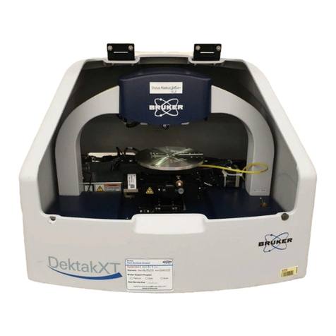
Bruker DektakXT Manual


P/N 980-389
DEKTAKXT
STYLUS PROFILER
INSTALLATION AND
MAINTENANCE MANUAL

©2011, Bruker Corporation
All rights reserved
Printed in the United States of America
May 31, 2011
COPYRIGHT NOTICE
The reproduction, transmission, or use of this document or its contents is not permitted without express
written authority. Offenders will be liable for damages. All rights reserved.
All configurations and specifications are subject to change without notice.
TRADEMARK NOTICE
Vision is a registered trademark of Bruker Corporation. All other brand or product names are trademarks
or registered trademarks of their respective holders.
Bruker Nano Surfaces Business
2650 East Elvira Road
Tucson, Arizona 85756
Phone: (520) 741-1044
Fax: (520) 294-1799

iii
TABLE OF CONTENTS
Safety Precautions . . . . . . . . . . . . . . . . . . . . . . . . . . . . . . . . . . . . . . . . . . . . . . . . . . . . . . 1
Unpacking the System . . . . . . . . . . . . . . . . . . . . . . . . . . . . . . . . . . . . . . . . . . . . . . . . . . . 1
Installing the Stylus Profiler . . . . . . . . . . . . . . . . . . . . . . . . . . . . . . . . . . . . . . . . . . . . . . . 6
Installing the Computer and Powering Up the System . . . . . . . . . . . . . . . . . . . . . . . . 15
Installing the Stylus. . . . . . . . . . . . . . . . . . . . . . . . . . . . . . . . . . . . . . . . . . . . . . . . . . . . . 22
Taking a Test Scan Measurement . . . . . . . . . . . . . . . . . . . . . . . . . . . . . . . . . . . . . . . . . 25
Electronically Configuring and Calibrating the Profiler. . . . . . . . . . . . . . . . . . . . . . . . 26
General Care and Maintenance . . . . . . . . . . . . . . . . . . . . . . . . . . . . . . . . . . . . . . . . . . . 26
Declaration of Conformity . . . . . . . . . . . . . . . . . . . . . . . . . . . . . . . . . . . . . . . . . . . . . . . 27


1
SAFETY PRECAUTIONS
The DektakXT™ stylus profiler is designed to minimize potential health and safety hazards during
normal installation, operation, and maintenance activities. However, as with any mechanical system
that uses electrical energy and compressed air, it contains some physical and electrical hazards.
Potential safety hazards associated with the system are clearly identified in this DektakXT User
Manual. In addition, warning and safety labels have been placed on the system where there exists a
potential for personal injury or damage to the system.
You should be aware of these potential hazards and the controls used to minimize them. If you have
any questions on environmental, health, or safety-related issues associated with the DektakXT
system, contact Bruker Customer Service at 1-800-873-9750.
UNPACKING THE SYSTEM
IMPORTANT! Before you begin to unpack the DektakXT stylus surface system, make
sure that you have already reviewed the facility requirement. At a minimum, you will need an
AC power strip or three free power outlets that match the voltage requirements of your tool. If
you have purchased the optional vibration isolation feet or a vibration isolation table, you will
also need compressed air. If you purchased one of the vacuum sample fixtures (chucks), you
will need a source of vacuum. The DektakXT must sit on a sturdy workbench or vibration
isolation table. If you have any questions, call Bruker Customer Service at 800-873-9750.
The unpacked components of the DektakXT system (minus the environmental enclosure) appear on
the next page.

2
IMPORTANT! Be sure to retain and store all installation tools and shipping brackets for
possible future use.
To unpack the DektakXT stylus surface profiling system:
1If you purchased the separate air isolation table, assemble it using the documentation inside the crate.
2Move the shipping boxes next to the vibration isolation table or sturdy workbench on which the system will
finally sit. During the unpacking process, this the table or bench that will hold the environmental enclosure.
Have an another large table nearby to hold the computer components and DektakXT tool as they are
unpacked.
3The shipping boxes for your DektakXT system appear in the picture that follows. You will have at least two
boxes—one for the environmental enclosure and one for the system itself. If you purchased the computer
and monitor from Bruker, you also will have one box for each of those items. If you purchased the air
isolation table, it will arrive in a wooden crate.

3
4This is the box for the Dell computer.
5After you open the box, you will see two smaller boxes on top of the computer. This first box contains all of
the cables, a mouse, documentation, backup CDs, and a shipping list. The smaller box contains the
keyboard.
6Here is the monitor box.You will see the base of the stand as you open the box, as shown in the second
picture below. Carefully slide the foam packing material out of the box and set it on a table with the stand on
top. Remove the stand and set it aside.

4
7Remove the top half of the foam, and you will see the monitor with the screen facing down. Take the
monitor out of the foam and set it on a clean, flat surface with the screen facing down. Attach the stand to
the monitor.
8This is the environmental enclosure box. Although it is similar in size to the box that contains the DektakXT
stylus profiler, it is much lighter.
9Remove the environmental enclosure and place it on a table near the final location of the DektakXT tool.
10 This is the box that holds the DektakXT stylus profiler. The tool is very heavy, so you will need two people
to lift it.

5
11 Lift the tool via both sides of the bridge. Be very careful not to touch the center where the head is located.
Place the tool on the surface that will be its final location—either a sturdy workbench or a vibration isolation
table. Make sure that there is plenty of front and back access room for performing the installation steps
outlined in the section that follows.
12 Remove and unpack the box containing one or more styli and the stylus exchange tool.
13 Remove the EMO box.
14 After you have unpacked all of the boxes, find the shipping checklist that was located in the computer
documentation and cable box. Do a complete inventory of all of the items shown on the checklist before
discarding the packing materials. If anything is missing, recheck the boxes. If you have any questions, call
Bruker Customer Service at 800-873-9750.

6
INSTALLING THE PROFILER
This section tells you how to install your new DektakXT stylus profiler. Make sure that the tool is
sitting on the system’s final location with ample access to both front and back. The environmental
enclosure should be sitting on a nearby table.
The first picture below shows a standard DektakXT system. The second picture shows the system
inside its environmental enclosure.
Hood-covered
measurement
head that
includes the
tower, camera,
illuminator, and
sensor head
Scan stage
System base
Sensor head and
stylus
Manual sample-
positioning stage
Block sample
fixture (chuck)
Base foot

7
IMPORTANT! Be sure to save all of the shipping straps, brackets, and screws in case you
need to ship the tool to another facility in the future.
1Loosen the orange Velcro shipping strap that is attached to the top of the stage. Then slide it out of the
slots in the two red shipping brackets and set it aside.
2Remove the shipping bracket on the front of the stage by loosening the screw with a hex head wrench. The
wrenches are in the box that contains the computer documentation and cable (see the previous section).
3Retighten the screw, since it is part of the stage assembly.
4On top of the glass block, you will see two red plastic brackets (see the picture above). One is located on
the front, and the other is located at the side. Carefully slide these brackets out, allowing the stage to rest
on the glass block. Make sure you don't leave any fingerprints or other debris on the glass. If you see any
dust on it, use clean air to blow it off.
5Go to the back of the tool, where you will see the rear shipping bracket and a cable with a small black
plastic cable clamp. Remove the screw from the bracket and set the bracket aside.
Red plastic bracket on top of
the glass block on the front
of the tool

8
6Place the screw through the plastic cable clamp and back into the stage. Tighten it.
7You will see two more shipping brackets on the front of the stage. Loosen the screws with a Phillips
screw driver, remove the brackets, and re-tighten the screws.

9
8While you are at the back of the tool, attach the cables before removing the other shipping brackets. The
connector panel is located on the right side. There are three USB connectors, so find the three USB cables
that shipped with the system. Your cables may look slightly different from the ones shown below, but this
will not be a problem. Attach the cables to the tool.

10
9Locate the power supply, a rectangular black box.

11
10 Attach the round connector to the power connector on the tool. Take care to rotate the connector properly,
so that the key fits.
11 The last cable is the tan-colored one that is attached to the EMO box. Plug it in and then return to the front
of the tool.
12 You will see a flat red plate above the stage This is the shipping bracket for the sensor head. Loosen the
two thumb screws and remove the plate.

12
13 If you have a wafer sample fixture (chuck), you will need to mount that next. Although yours may not look
exactly like this one, it will still mount with three screws.
14 Using the appropriate hex head wrench, attach the sample fixture as shown.
15 You will need to remove the head cover to gain access to the Z axis shipping bracket. Use care when
sliding the cover up, so as not to damage these cables.

13
16 Lift up the right side first; this will be easier.
17 Use the appropriate hex head wrench to remove the two silver screws.
18 Remove the Z-axis shipping bracket.
19 Use a small Phillips screwdriver to remove the two black screws from the bracket.

14
20 These two screws must be installed back in the holes in the Z axis bearing, as shown below.
21 Now replace the head cover, lowering the left side first.
22 Place the environmental over the fully assembled DektakXT tool. Make sure that the enclosure does not
touch the edges of the DektakXT itself.
NOTE – Always take measurements with the enclosure over the tool with the door closed,
since air currents and noise will affect measurements without this protection.
23 Pass the three power cables through the opening at the bottom of the back of the environmental enclosure.

15
INSTALLING THE COMPUTER AND POWERING UP THE
SYSTEM
1Remove the software key from inside the Vision64 CD case.
2Insert the key into one of the USB ports in the back of the computer.
Other manuals for DektakXT
4
Table of contents
Other Bruker Measuring Instrument manuals

Bruker
Bruker DektakXT User manual

Bruker
Bruker S1 TRACER User manual

Bruker
Bruker minispec LF Series User manual
Bruker
Bruker VERTEX 70v User manual

Bruker
Bruker CTX User manual

Bruker
Bruker minispec mq20 User manual

Bruker
Bruker M4 TORNADO User manual

Bruker
Bruker D8 Discover Manual

Bruker
Bruker CTX User manual

Bruker
Bruker BMS User manual