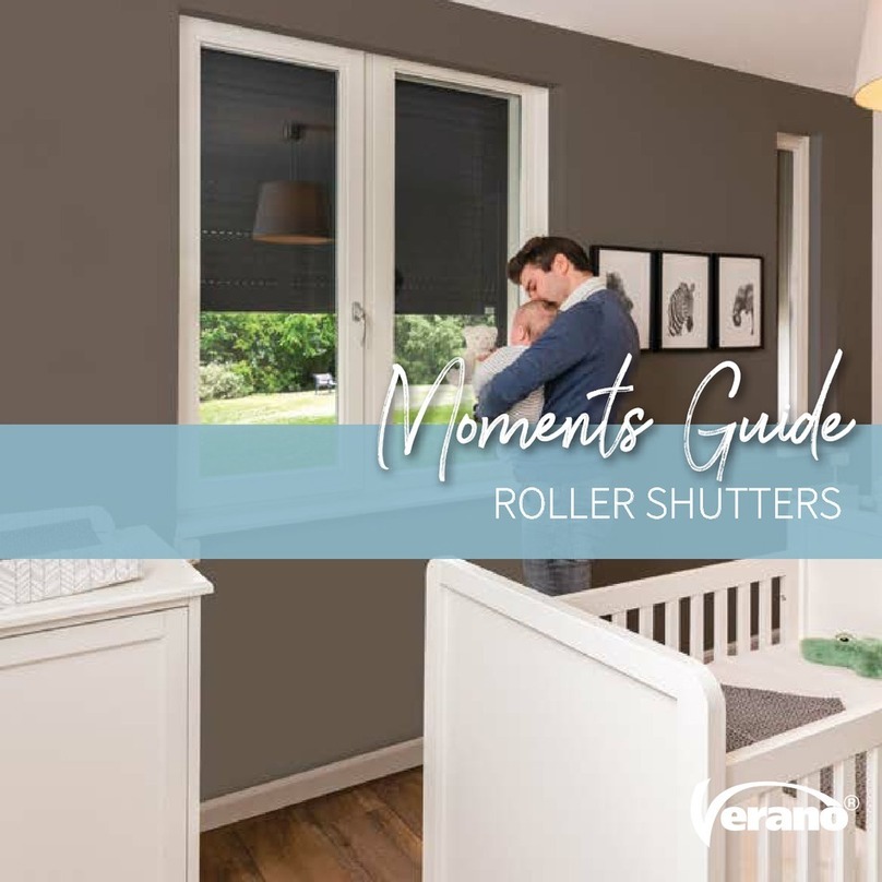
Verano RV40 ecoline User manual

INSTALLATION MANUAL
ROLLER SHUTTERS
RV40 - RV41 ecoline

INSTALLATION MANUAL ROLLER SHUTTERS
1771-190826EN
1
Subject to misprints, errors and technical modifications.
Content
Package 1
1. Armor in box
2. Control
a. manual control: cord or strap winding mechanism
b. electrical control: switch + plug
c. remote controlled: remote control + plug
Package 2
3. Two guides
4. Screw caps
5. End caps (only with HTF side-guides)
Necessary tools
• Drilling machine
• Metal drill 6/10 mm
• Masonry drill 6/10/12/20 mm
• Crosshead screwdriver
• Tapeline
• Level
• Pencil
In case of electrical control:
• Nippers
• Flathead screwdriver
33
4
5
1

INSTALLATION MANUAL ROLLER SHUTTERS
1771-190826EN
2
Subject to misprints, errors and technical modifications.
Important before installation
Be careful for damages
Don’t use a knife or any other sharp object when opening the packing. This may cause damage to the content of the
package. Put the content of the package on a so surface. Be careful when drilling, falling drill cuttings can cause damages.
Check if the window frame or façade is at and smooth.
General warning
Mounting the Verano® product yourself is at your own risk. Only use this instruction as a tool and for the mounting of
this specic Verano® product. If you cannot mount the product yourself, you can always opt for professional mounting.
The mounting team of Verano® is pleased to help you.

INSTALLATION MANUAL ROLLER SHUTTERS
1771-190826EN
3
Subject to misprints, errors and technical modifications.
1.1 Marking the mounting-holes
1. Place the le guide vertical, at the right height, against the façade or the window frame.
Attention! The guides have an open and closed side. The open side needs to be on the window side and conducts the
slats. You may not drill in the open side!
2. Mark the mounting-holes on the guides. Make sure that the mounting-holes are in a stone and not in the seam!
The rst hole at the xation point of the box, needs to be drilled at least 15 cm from the edge. This space must be kept
free for the cover bracket.
3. Place the right guide at the right height and width against the wall and mark the mounting-holes the same way.
Attention! The le- and right guide need to be exactly levelled at the top and bottom. Use a shelf and level to check this.
1. Instruction placing roller shutter (outside)
> 15 cm
±
50 cm
±
50 cm
Y
op de dag, HTF geleider
in de dag, LHTF geleider
Y = guide height
Screws per guide
Y < 125 cm : 2x
Y = 125-225 cm : 3x
Y > 225-285 cm : 4x
Installation on the wall, HTF guide
Installation between two walls, LHTF guide

INSTALLATION MANUAL ROLLER SHUTTERS
1771-190826EN
4
Subject to misprints, errors and technical modifications.
Y
13 mm
Y
13 mm
op de dag,HTF geleider in de dag, LHTF geleider
6 mm 6 mm10 mm
> 15 cm > 15 cm
1.2 Drilling mounting-holes in the guides
Make sure that the holes are drilled precisely 13 mm from the side.
Installation on the wall: first drill a hole of 6 mm through both layers of the guide. After that, drill the top hole with
a 10 mm drill. Later, the plastic screw caps are placed here.
Installation between two walls: drill all the holes with a 6 mm drill.
1.3 Rubbers
Cut o 15 mm rubber, sloped on the top of
both guides. This to prevent jamming of the
armor in the run funnel.
15 mm
1.4 Sloping windowsill
Do you have a sloping windowsill? First saw the LHTF guide in the same angle as the slope of
your windowsill. This is only necessary when mounting between two walls.
in de dag, LHTF g
eleider
Installation on the wall, HTF guide Installation between two walls, LHTF guide
Installation between two walls,
LHTF guide

INSTALLATION MANUAL ROLLER SHUTTERS
1771-190826EN
5
Subject to misprints, errors and technical modifications.
1.6 Hole for the control
1. Accurate mark the transit hole where the power cord or band needs to come inside for the control. This needs to be at
exactly the same height as the place where the power cord or band comes out of the box!
2. Drill the hole for the wall transit.
Check before drilling if there are no pipes and such are in the wall!
Always use a shelf on the inside of the house, so the stucco can not be damaged.
Transit hole for a pull up band: 20 mm (drill 10 mm, than 20 mm).
Transit hole for a pull up cord: 12 mm.
Transit hole for an electrical power cord: 10 mm.
op de dag, HTF geleider in de dag, LHTF geleider
muurkozijn muurkozijn
1.5 Mounting the guides
1. Place the guides back in the façade or the window frame. Make sure that the guides are perpendicular and run parallel
to the wall. You can mark the drill holes according to the holes in the guides.
2. Drill the nal holes. Take the size of the screws and wall plugs you are going to use into account.
3. Screw the guides. Don’t screw the top screws tight yet. This way the guides can still be put forward when placing
the box.
Caution!
In case of low gutter or eaves.
When a roller shutter needs to be mounted below a low
gutter or eaves, it is necessary to rst place the box on
the guides before the guides are screwed on to the wall.
Be extra careful with the mounting. The cover brackets
are vulnerable! To prevent breaking of the cover
brackets, you always need to li the roller shutter with
two persons at the xation point of the box on the side
guides.
Installation between two walls, LHTF guideInstallation on the wall, HTF guide
wall wallwindow
frame
window
frame

INSTALLATION MANUAL ROLLER SHUTTERS
1771-190826EN
6
Subject to misprints, errors and technical modifications.
1
snoer band
2
1.7 Placing the box onto the guides
1. Remove the foil on the back of the box. You can leave the foil on top of the box on.
2. Li the box with two persons.
3. Conduct the electrical power cord or the pull up band through the drilled transit hole to the inside. Make sure that the
pull up band is not twisted.
4. Slide the cover brackets, that protrude under the box, in the guides. This needs extra caution, the cover brackets are
very vulnerable!
5. Screw the top screws tight in the guides.
power cord band

INSTALLATION MANUAL ROLLER SHUTTERS
1771-190826EN
7
Subject to misprints, errors and technical modifications.
1. Disassemble the front cover of the box.
1.8 Fixating the box to the wall (optional )
Especially for larger dimensions it is advisable to xate the sidecovers to the wall. This creates a better connection and
the legs of the sidecover are less burdened by the pantser weight.
2. Drill two mounting holes through the sidecover in the wall with a masonry drill.
Fixate the sidecover against the wall with 2 screws. Use screws, matching plugs and rings of a good quality.
1.9 Finishing touch mounting outside
1. Remove the last foil on top of the box and the guides.
2. Close the holes with the protection caps.
3. Place, when needed, the end caps on the bottom of the guides (view gure on page 1). The end caps may NOT be
placed when the roller shutter closes on the windowsill or the ground/oor. In that case there will be an opening
of 4 mm when closing the roller shutter.
4. Lute the top and sides of the box.
Electrical control: for the prevention of water dripping inside.
Manual control: for prevention of dirt and moisture on the power cord.
Transparent lute gives the best result.

INSTALLATION MANUAL ROLLER SHUTTERS
1771-190826EN
8
Subject to misprints, errors and technical modifications.
1. Put the pull up band through the pulley on
the inside. Make sure that the pull up band is not
twisted.
2. Place the pulley in to the control hole.
3. Determine the position of the winding
mechanism and mark the two holes on the
window frame or the wall.
Attention! The winding mechanism and the band
need to be in one line!
4. Drill the holes.
5. Place the wall plugs and mount the winding
mechanism with two recessed screws.
6. Fold the end of the pull up band double and
snip a small hole.
5mm
50mm
2. Installation manual control (inside)

INSTALLATION MANUAL ROLLER SHUTTERS
1771-190826EN
9
Subject to misprints, errors and technical modifications.
1
2
1
2
2
10. Remove the red bandage on the outside of the roller shutter and carefully lower the roller shutter.
The manual controlled roller shutter is now ready for use and can be controlled freely from the inside.
7. Pull the end of the pull up band through the
winding mechanism and place it across the
small hole so that it is tightened.
Caution! You may not shorten the band in an early
stage! The length of the band is needed when you
close the roller shutter.
8. Break o the plastic hook so that there is tension
on the winding mechanism. Now the full length
of the band automatically roles on to the winding
mechanism.
9. Place the end cover on the winding mechanism.

INSTALLATION MANUAL ROLLER SHUTTERS
1771-190826EN
10
Subject to misprints, errors and technical modifications.
1. Determine the position of the
switch and mark the 2 holes on the
wall indoors.
2. Drill the holes with a 6 mm drill.
3. Open the switch using a at
screwdriver.
4. Place the wall plugs and mount the
switch with two recessed screws.
Make sure that the power is turned
o and without tension!
Ø6
230 V
3. Installation electrical control (inside)
Optioneel
230 V
Optional

INSTALLATION MANUAL ROLLER SHUTTERS
1771-190826EN
11
Subject to misprints, errors and technical modifications.
5. Connect the 4-core power cord of the motor and the 3-core power cord + switch, following the schedule.
If necessary, consult an installer.
Motor le (seen from the outside) Motor right (seen from the outside)
Optioneel
230 V
6. Mount the switch.
In a situation with a wireless remote
control, the 3-core power cord can
directly be connected to the socket.
7. Put the switch in the socket and
turn on the power.
The roller shutter is now ready to be
controlled.
* View the included SOMFY instruction for setting the remote control.
*
geel/groen
blauw
bruin
geel/groen
blauw zwart
bruin
bruin
geel/groen
blauw
bruin
geel/groen
blauw
zwart
bruin
bruin
geel/groen
blauw
bruin
geel/groen
blauw zwart
bruin
bruin
geel/groen
blauw
bruin
geel/groen
blauw
zwart
bruin
bruin
brown
brown
brown
brown
brown
brown
black
black
blue
blue
blue
blue
yellow/green
yellow/green
yellow/green
yellow/green
Optional*
This manual suits for next models
1
Table of contents
Other Verano Indoor Furnishing manuals
Popular Indoor Furnishing manuals by other brands

BIG FURNITURE WAREHOUSE
BIG FURNITURE WAREHOUSE Columbia 305 quick start guide

Argos
Argos Hygena Genoa 464/2718D Assembly instructions

ifs
ifs ANNALISA CHAIR Assembly instructions

BMB Beschlaege
BMB Beschlaege E-SMART 2M2S Assembly instructions

Bentley Designs
Bentley Designs 2690-19 manual

Costway
Costway OP70829 user manual