manuals.online logo
Brands
  1. Home
  2. •
  3. Brands
  4. •
  5. VERIS INDUSTRIES, INC.
  6. •
  7. Relay
  8. •
  9. VERIS INDUSTRIES, INC. V101 User manual

VERIS INDUSTRIES, INC. V101 User manual

Other VERIS INDUSTRIES, INC. Relay manuals

VERIS INDUSTRIES, INC. V100DC User manual

VERIS INDUSTRIES, INC.

VERIS INDUSTRIES, INC. V100DC User manual

VERIS INDUSTRIES, INC. V102 User manual

VERIS INDUSTRIES, INC.

VERIS INDUSTRIES, INC. V102 User manual

VERIS INDUSTRIES, INC. V222 User manual

VERIS INDUSTRIES, INC.

VERIS INDUSTRIES, INC. V222 User manual

Popular Relay manuals by other brands

Woodward BU1-DC2 manual

Woodward

Woodward BU1-DC2 manual

ABB SSR32 product manual

ABB

ABB SSR32 product manual

Siemens SIRIUS 3UG4633 operating instructions

Siemens

Siemens SIRIUS 3UG4633 operating instructions

Siemens SIRIUS 3TK2824 A.20 Series Original operating instructions

Siemens

Siemens SIRIUS 3TK2824 A.20 Series Original operating instructions

Shelly Pro Series user manual

Shelly

Shelly Pro Series user manual

GE MVAX 11 Technical manual

GE

GE MVAX 11 Technical manual

ABB RELION REF615R manual

ABB

ABB RELION REF615R manual

Kemo Electronic B197 quick guide

Kemo Electronic

Kemo Electronic B197 quick guide

Seg MRM3 manual

Seg

Seg MRM3 manual

Basler BE1-700C manual

Basler

Basler BE1-700C manual

CD Automation REVEX 2PH 280A user manual

CD Automation

CD Automation REVEX 2PH 280A user manual

ABB SPAJ 142 C User manual and technical description

ABB

ABB SPAJ 142 C User manual and technical description

Ruelco 1S04 Operation manual

Ruelco

Ruelco 1S04 Operation manual

Basler V3E Z1P B2C1F instruction manual

Basler

Basler V3E Z1P B2C1F instruction manual

GE DGP instruction manual

GE

GE DGP instruction manual

Kyongbo Electronics GDR-D01 user manual

Kyongbo Electronics

Kyongbo Electronics GDR-D01 user manual

Eaton easyE4 series Application note

Eaton

Eaton easyE4 series Application note

Siemens BD2-AK03X/FS Series installation instructions

Siemens

Siemens BD2-AK03X/FS Series installation instructions

manuals.online logo
manuals.online logoBrands
  • About & Mission
  • Contact us
  • Privacy Policy
  • Terms and Conditions

Copyright 2025 Manuals.Online. All Rights Reserved.

Z203391-0D PAGE 1 ©2012 Veris Industries USA 800.354.8556 or +1.503.598.4564 / suppor[email protected] 05121
Alta Labs, Enercept, Enspector, Hawkeye, Trustat, Veris, and the Veris ‘V’ logo are trademarks or registered trademarks of Veris Industries, L.L.C. in the USA and/or other countries.
TM
REL AYS INSTALLATION GUIDE
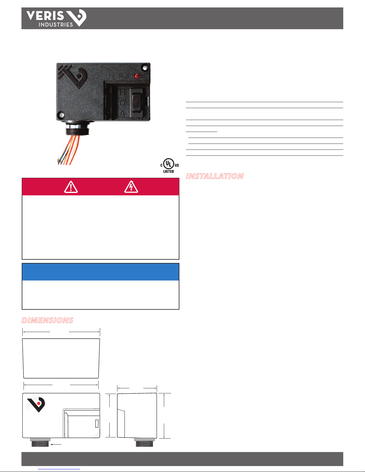
10A SPST Enclosed Relay With HOA Switch
Installer’s Specifications
Operating Temperature -40° to 55°C (-40° to 131°F)
Operating Humidity 10-90% RH, non-condensing
Expected Relay Life Electrical (@ rated current) 100,000 cycles;
Mechanical (unpowered) 10,000,000 cycles
Relay Status LED ON=energized
Wire Specications:
Lead Length 14” (356mm) min.
Gauge UL1015; Coil: 18AWG; Contacts: 16AWG
Insulation Class 600VAC RMS
Agency Approvals UL508 enclosed device listing, pollution degree 2
V101 V101
DIMENSIONS
NOTICE
• This product is not intended for life or safety applications.
• Do not install this product in hazardous or classified locations.
• The installer is responsible for conformance to all applicable codes.
• Mount this product inside a suitable fire and electrical enclosure.
INSTALLATION
Disconnect and lock out all power sources before beginning the
installation.
1. Using the threaded nipple, connect the relay to the desired enclosure through a
knock out hole.
2. Secure with the conduit nut provided.
3. Connect coil wires:
• Choose the coil common lead (white with yellow stripe) and connect it to
the common (-) source termination point.
• Choose either the low voltage (10-30VAC/DC, white with blue stripe) or
high voltage (120VAC, white with black stripe) lead, depending on the
application requirements, and connect it to the (+) source termination
point.*
NOTE: When connecting the control side of this device (#18 wires) to power
line circuits, provide current limiting at 7 amps max.
4. Connect relay contacts:
• Choose the two orange wires (N.O. contact) and connect to the switched
load.
5. Secure the enclosure and reconnect power.
* Isolate or insulate all non-terminated wires according to local electrical code requirements, i.e.
wire nut.
2.0"
(52 mm)
2.5"
(64 mm)
3/4" NPT Nipple
2.3"
(59 mm)
4.0"
(103 mm)
3.8"
(97 mm)
HAZARD OF ELECTRIC SHOCK, EXPLOSION, OR ARC FLASH
• Follow safe electrical work practices. See NFPA 70E in the USA, or applicable local codes.
• This equipment must only be installed and serviced by qualied electrical personnel.
• Read, understand and follow the instructions before installing this product.
• Turn o all power supplying equipment before working on or inside the equipment.
• Use a properly rated voltage sensing device to conrm power is o.
DO NOT DEPEND ON THIS PRODUCT FOR VOLTAGE INDICATION
Failure to follow these instructions will result in death or serious injury.
DANGER
Z203391-0D PAGE 2 ©2012 Veris Industries USA 800.354.8556 or +1.503.598.4564 / suppor[email protected] 05121
Alta Labs, Enercept, Enspector, Hawkeye, Trustat, Veris, and the Veris ‘V’ logo are trademarks or registered trademarks of Veris Industries, L.L.C. in the USA and/or other countries.
TM
V101 INSTALLATION GUIDE
HOA POSITIONS
WIRING EXAMPLE
Nipple mount directly to a panel
Nipple mount to a 2x or 4x electrical box
To Load
To Controls
COIL
CONTACTS
To Load
To Controls
Wire
Nut
C
O
I
L
CONTACTS
WIRING COLOR CODES
CONTACT AND COIL SPECIFICATIONS
Pull in Voltage AC DC
10-30V..................................... 8 9
120V........................................ 78
Drop Out Voltage AC DC
10-30V..................................... 2 3
120V........................................ 18
Voltage Coil Current
AC DC
10V.......................................... 25mA 14mA
24V.......................................... 31mA 16mA
30V.......................................... 39mA 18mA
120V........................................ 22mA -
TYPICAL COIL PERFORMANCE
CONTACT RATINGS
Resistive.............. 10A@250VAC
Motor.................... 1/3HP@120VAC
Gold Flash............. Yes
10-30VAC/DC
120VAC
LOW
wht/blue
COMM
wht/yellow
HI
wht/black
CONTACT OUTPUTCONTROL SYSTEM INPUT
Common
HAND
OFF
AUTO
Up position: contacts are closed.
Middle position: contacts are open.
Down position: control system actuates the contacts.