Verner 13 Specification sheet

EXPERTONHEAT
ENISO9001:2008
OPERATIONAND
INSTALLATIONMANUALFORTHE
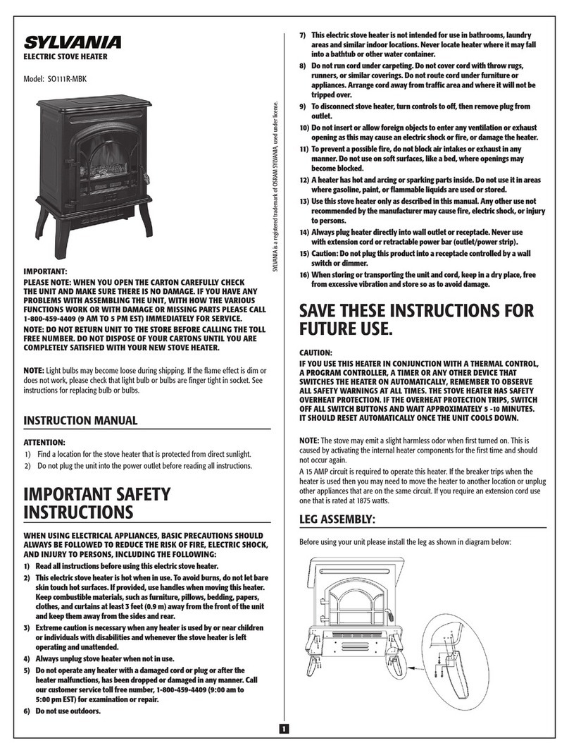
VERNER13/10
Woodburningboilerstove
ProductNumber:
b212.66197.011111
Issuedon:01.11.2011
Translatedon16.09.2013
SoleUKDistributor:
AshburnStoves
www.ashburnstoves.co.uk
08455390364


1|Page
CONTENTS
IMPORTANTINFORMATION....................................................................................................2
INTRODUCTION.......................................................................................................................2
TECHNICALDESCRIPTION........................................................................................................3
BOILERDETAILS.......................................................................................................................4
TECHNICALDETAILS.................................................................................................................6
ASSEMBLYANDINSTALLATION...............................................................................................7
Location.......................................................................................................................................7
Hearth..........................................................................................................................................7
Airsupplytoboiler......................................................................................................................8
Buildingin(forboilerwithrearstoking).....................................................................................9
Connectiontothechimney.......................................................................................................12
Connectiontotheheatingsystem............................................................................................14
Automaticcoolingloopsystem.................................................................................................15
Frontdoorhingereversal..........................................................................................................16
CASINGASSEMBLYINSTRUCTIONS........................................................................................16
OPERATIONINSTRUCTIONS...................................................................................................20
Lightingtheboiler......................................................................................................................20
Stoking.......................................................................................................................................21
Outputcontrol...........................................................................................................................22
Combustioncontrol...................................................................................................................22
Stableheatoperation................................................................................................................23
Fuel............................................................................................................................................23
Ashremoval...............................................................................................................................25
Usingtheboilerforcooking......................................................................................................25
Maintenanceandrepair............................................................................................................26
Dooradjustment........................................................................................................................27
DISPOSALOFPACKAGING.....................................................................................................27
BOILERDISPOSALATTHEENDOFITSLIFE.............................................................................27
SUPPLIEDACCESSORIES.........................................................................................................27
SAFETYINFORMATION..........................................................................................................28
BOILERCONNECTIONEXAMPLES...........................................................................................29
GUARANTEECONDITIONS.....................................................................................................33
SERVICERECORD...................................................................................................................35

2|Page
IMPORTANTINFORMATION
READTHESEINSTRUCTIONSTHOROUGHLYBEFOREINSTALLING,OPERATINGORSERVICING
THISAPPLIANCE.FAILURETODOSOCOULDPUTLIVESATRISK!
ItisarequirementundertheVERNERa.s.warrantysystemthattheinstallationofthestoveis
carriedouteithertolocalauthoritybuildingcontrolapprovalorbyaCompetentPerson
registeredwithaGovernmentapprovedCompetentPersonsScheme.HETASLtdoperatesucha
schemeandalistingoftheirRegisteredCompetentPersonscanbefoundontheirwebsiteat
www.hetas.co.uk.
Theanswertosafeandefficientwoodburningisthroughcorrectinstallationandproper
operationwhichcanonlybeachievedbygoodplanning.Pleasereadthefollowinginstructions
carefullytogetthebestfromyournewpurchase.
TheinteriorboileristestedandapprovedforinstallationandusetoEN13240:2001
INTRODUCTION
TheVERNER13/10interiorboilerisawoodburningroomheaterstovewithawaterheat
exchangergiving10kWoutputtothecentralheatingsystem.Itisdesignedforcontinuous
operationasthemainheatsourcefordwellingspaces,houses,cottages,farmhousesand
similarbuildingswithaheatlossupto13kWandassupplementaryheatingforapplications
withaheatlossover13kW.
Longburningtimes,greateroutputadjustabilityandlowoperationandmaintenance
requirementsallowforveryeasyandcomfortableoperation.Itshighefficiencyguaranteesa
verylowrunningandenvironmentalcost.
Modernhomeshavesuperiorlevelsofinsulationandarefarmoreenergyefficientwhich
makeshomeseasiertoheatandretainheatmuchbetter.Vernerwoodburningappliancesare
carefullydesignedsothattheywillfunctioncorrectlyinmodernenergyefficienthomes.The
moreenergyefficientahouseis,thelessfuelisrequiredtoheatit,meaninglessimpactonthe
environment.
Superiordesignandthehighqualityofconstructionguaranteealonglifespanforyour
investment.
Otheradvantagesarethestableheat(slumber)modethatlastsbetween8to12hours,ahigh
heatoutputratiointothecentralheatingsystem(77%)andlongburningtimeofupto3hours
atfulloutput.
Theboilerisdesignedasacentralheatingappliancewithprimaryairfedtothefuelthroughthe
grate.Thereisalsosecondaryandtertiaryairroutedintothecombustionchamber.
Recommendedfuelsaredrywoodorwoodbriquettes.35cmlonglogswithadiameterupto
20cmcanbeburnedintheboiler.Fossilfuelssuchas,butnotlimitedto,coaloranthraciteare
notsuitableforuseinthisappliance.
Theboilerissuppliedintwomodels:eitherthebasicdesign(withfrontstokingdoorsand
ashpan)orarearstokingmodel(withfrontandrearstokingdoorsandrearashpan).Therear
stokingmodelisdesignedforbuildingintoawallanditisstokedandcleanedfromoutsideof
themainlivingarea.Thisgivesownersthehugeadvantageofkeepingtheirmainlivingareas
freeofdust,sootandsmoke.

3|Page
TECHNICALDESCRIPTION
Theboilerbody–(1)comprisesweldedsteelmetalsheetsof4and5mmthickness.Theheat
exchangerextendsdowntothebaseofthecombustionchamber'ssideandrearwallsgiving
lowerappliancecasingtemperatures.Thetopoftheheatexchangeriscarefullydesignedto
extractthemaximumheatfromthefluegas.Thecombustiongaspassesthroughtwoparallel
channelsofrectangularprofilewhichhousethreemovablecleaningvanes(7)ineachchannel
thatarelinkedtothedamperrod.Acoolingloopisincorporatedintotheupperpartoftheheat
exchangerwithtwoconnectionsattherear(9).
Thecombustionchamberislinedwithmoulded,highquality,ceramicinsulationwhich
incorporatesreinforcingfibresofheatresistantsteel.Theinsulationlinesthecombustion
chamber'srearwall.Theyaregroovedtodirectthepre‐heatedtertiaryair.Thefrontofthe
fireplaceisequippedwithafuelbarmadeofheatresistantsteel(16)tocontainthefuel.
Themovablegrateisoperatedbytheriddlingrod(12)causingtheashtofallandbecollected
bytheashpan.Withtheriddlingrodextended,additionalairpassesthroughthegrate(18)
duringlightingoftheappliance.
Atthetopofthecombustionchamberadamperiscontrolledbythedamperrod(13).During
lighting,thedamperrodisextendedallowingthefluewaystoopenprovidingminimal
restrictionoffluegases.
Therearstokingmodelhasriddlingrodanddamperattherear,allowingittobestokedand
cleanedfromtherear.Theashpanisaccessiblefromtherearonly,withthefrontaperture
blankedoff(31).Thedoorshaveahollowframeandtheairwashwhichkeepstheglassfreeof
sootissuppliedthroughtheframe.Therearetwoholeswithslidersprovidingairwashflowand
thesecanbeadjustedtoincreasetheflowduringlightingorduringdifferentstatesofoutput.
Thelargeceramicglass,withtemperatureresistanceupto800°C,hasaspeciallayerthat
reflectsthermalradiation.Thisincreasestheproportionoftheheatoutputwhichisdirected
intothecentralheatingsystem.Thestokingopeninghasahingedsteelplatealongitsupper
edgewhichpreventssmokespillageintotheroomduringstoking.
Thestokingdoorcanbereversedsothatithingesontheoppositeside.
Heatoutputregulationiscontrolledbyamechanicalthermostaticactuator(6)coupledtoaflue
gastemperaturesensor(21).Thisoperatesaflapontheairintake.Outputisadjustedbya
wheel(27).
Thestableheatregulatorisequippedwithaservomotor(28),whichclosesaflapontheair
intake.Theservomotorisenergised(closingtheflap),ifthefluegastemperaturedropsbelow
thevaluesetonthestableheatthermostat(23)bythestableheatregulationwheel(25),orif
thewatertemperatureexceedsthevalueadjustedontheemergencythermostat(22).Closing
oftheflapisshownbytheretractionoftheindicator(26).Normaloutputcontrolisrestoredby
manuallypullingouttheindicatorwhichwillre‐opentheflap.
Asafevoltageof12Vissuppliedtotheboiler.Thepowersupply(mainsadapter12V‐1A)is
connectedtotheboilerwitha4mlongcablewhichmustnotbeshortened.
Surfacetreatmentofthermallyexposedparts(doors,ashpan,cookingplates)isprovidedbya
heatresistantcoatingofmattblackpaint.Thesurfacetreatmentofotherexternalboilerparts
(sides,frontandtopcovers)isprovidedbypowdercoatedenamel.

4|Page
BOILERDETAILS
SectionalsideviewFrontview‐partiallysectional Rearview
Designwithrearstoking Topview Detailofcontrols

5|Page
1Boilerbody 18Grate
2Frontstokingdoor19Anti‐smokeplate
3Flueconnection 21Fluegastemperaturesensorforoutput
regulation
4Ashpan22Overheatwatertemperaturesensor
5Topcover 23 Fluegastemperaturesensorforstable
heatmode
6Thermostaticheatoutputactuator 25Wheelforadjustmentofstableheat
mode
7Heatexchangercleaningvanes 26Indicatorforstableheatmodestatus
8Waterconnections1¼”BSP27Heatoutputcontrolwheel
9Coolingloopconnections½”BSP 28Stableheatmodeservomotor
10Thermostatmountinglocations ½”BSP 30Rearstokingdoor
11Primaryairsetup(factoryadjusted) 31Additionalaircontrolforappliance
lighting
12Riddlerrod32Rearriddlingrod
13Damperrod33Reardamperrod
14Dataplate34Smallceramicinsulation
15Sidecover35Ashpanaperturecover
16Fuelbars36Windowairwashadjustment
17Warmingplate 37Externalairsupplyconnection

6|Page
TECHNICALDETAILS
Totalratedthermaloutput13kW
Ratedoutputtocentralheating10kW
Ratedoutputtotheroom3kW
Efficiency 87.4%
Fuelconsumptionatratedoutput 3.6kg/hour
Burningdurationoffullfuelload(11kgatratedoutput) 3hours
Combustionchambercapacity100litres
Stokingareacapacity 60litres
Ashpancapacity16litres
Combustiongastemperatureintochimney 250oC
Combustiongasmassflowrate(atratedoutput) 9.5g/s
Totalweight 255kg
Watercapacityofboiler 30litres
Maximumhydraulicpressureloss(70/90oC) 5Pa
Maximumoperationalpressure 2bar
Supplyvoltage(formainsadapter12V‐1A) 230V/50Hz
Electricenergyconsumptionperheatingseason1kWhour
Emissionclassofcarbonmonoxide1
Minimumtransportbodyweight 200kg
Minimumrequiredchimneydraught 15Pa
Masonrychimneyminimumcross‐section 250cm2
Minimumfluesize175mm
Minimumrecommendedflueheight5m
Recommendedfuels woodlogs(moisturecontentupto20%)andwoodenbriquettes

7|Page
ASSEMBLYANDINSTALLATION
Theboilerinstallationmusttobecarriedoutincompliancewiththeoperatingandinstallation
manual.
AllrelevantBritishStandardsandEuropeannormsandstandardsmustbeobservedduring
installation.TheboilermustbeinstalledinaccordancewithBuildingRegulationsandapproved
documents.
Beforeboilerinstallation,theinstallershouldcheckthattheinformationontheboilerdata
platecorrespondswiththeoperationandinstallationmanualandtheapplianceissuitablefor
theintendeduse.Acheckshouldalsobemadefordamagedandmissingpartswhichshouldbe
notifiedtothesupplierbeforeinstallation.
Location
Aminimumclearanceof5mmshouldbemaintainedbetweenthesidesandrearoftheboiler
andnon‐combustiblesurfaces.
Minimumdistancesfromcombustiblesurfaces
800mmtothefront
100mmtothesides
200mmtotherear‐frontstokingmodel
800mmtotherear‐rearstokingmodel
200mmabovethetopcover
3xdiameteroftheun‐insulatedconnectionfluepipe
Seemanufacturer'sinstructionsforclearancesforinsulatedfluepipesandchimneys
Clearancestocombustiblesurfacescanbereducedinsomecircumstances.ConsultDocumentJ
oftheBuildingRegulations.
Theboilerandfluemustbeinstalledtoallowaccessforcleaning.Itisnecessarytoremovethe
warmingplateandapplianceflueconnectortocleanandmaintaintheupperareasoftheheat
exchangerandcleaningvanes.
Hearth
Theboilerstovedoesnotrequireaconstructionalhearth.Howevertocomplywithbuilding
regulationsitmustbelocatedonanon‐flammablehearthofminimum12mmthickness.The
hearthtemperaturedoesnotexceed100oC.Thehearthmustextendaminimumof225mmin
frontand150mmtoeachsideoftheappliance.Thehearthmustprojectaminimumof225mm
attherearoftherearstokingmodel.Itisacceptabletofittheapplianceontopofapurpose
madeglasshearthbutconsiderationshouldbegiventotheapplianceweight.Theinstaller
mustensurethattheflooronwhichtheboileristobemountedhassufficientcarryingcapacity.
Thehearthmustbeflatandlevel.

8|Page
Airsupplytoboiler
Theboilertakescombustionairfromtheroom(approx.30m3/houratratedoutput).
Buildingregulationsstatethatadwellingconstructedpriorto2008shouldhavenatural
provisionofdraughtsufficientforthefirst5kWoftheapplianceratedinput.Adwellingbuilt
after2008willhavemuchstricterguidelinesregardingairtightnessandthereforethefirst5kW
oftheapplianceratedinputmustbeconsideredincombustionaircalculations.
totalfreeairdirectfromoutside
Constructionpriorto20084400mm2
Constructionin2008orafter7150mm2
Thecombustionairventshouldbelocatedinaplacewhereitisunlikelytobeblockedbythe
enduser.Itispreferabletoplacetheventinapositionsoasnottocausedraughtsornuisance.
Ventsmustbeofthenon‐closingtypeandmustnotcontainaflyscreen.
VERNERrecommendsthattheboilertakescombustionairfromtheheatedbuildinginterior
howeveritispossibletoprovidecombustionairdirectlytotheapplianceusinganexternalair
supplykitconsistingofaflexiblepipeandexternalairvent.Inthisway,airforcombustionis
suppliedtotheboilerdirectlyfromoutside.
Weonlyrecommendconnectionofanexternalairsupplyinbuildingsbuilttopassivehouse
standardsorwithcontrolledventilationutilisingheatrecovery.Theonlyexceptiontothisis
wheretheapplianceisfittedinaroomcontaininganextractorfanwhichcouldcausetheflue
systemtooperatepoorly.Theconnectioncanbeprovidedbyanon‐combustibleflexiblehose
of100mmdiameterconnectedtothestoveforaminimumlengthof500mm.Theairduct
mustbedesignedsothatitspressurelossataflueflowof30m3/hourdoesnotexceed3Pa.The
ductcrosssectionmustnotbelessthan75cm2anditslengthshouldnotexceed5m.
Ifitisfoundduringoperationthattheboilersmokesexcessivelywhilststoking,ensurethatthe
flueisuptotemperatureandthedamperrodiswithdrawn.Ifexcessivesmokingcontinues,
thenopenawindowinthesameroomastheboiler.Shouldthesmokingreduceorbe
eliminated,extrapermanentventilationshouldbefittedtotheroom.
Iftheboilerisoperatedtogetherwithanotherappliancerequiringanairsupply,theair
requirementcalculationshouldbecarriedoutassumingbothappliancesareoperatingat
maximumoutput.Extractorfansinthesameoradjacentroomsastheboilershouldbetaken
intoaccount.

9|Page
Buildingin(forboilerwithrearstoking)
Thisboilerismodifiedforwallbuilding‐in.Positioningmustallowforthedisconnectionand
removaloftheboilerfromtheheatingsystemifrequired.
Wallbuilding‐inusingtheoptionalmetalliner
Themetallinerallowstheinstallationoftherearstokingmodelwithinthefabricofthewall.
Thispermitstheappliancetobeoperatedfromanotherroomwhilstthebenefitsofthestove
canbeenjoyedfromthelivingarea.Thelinerissetintoanopeningoftheappropriate
dimensionsandstillallowstheuseofthewarmingplateontopofthestovebutconcealsthe
fluefromsight.Werecommendfixingthelinerapprox.3mmbehindfinishedplasterlevelto
allowtheuseofplasterreinforcingfabric(scrimtape)priortoplasteringlevelwiththe
surroundingwall.
Thelinerisnotdesignedtosupportanystructureandastructurallintelmayberequired.
Theboilerisinsertedintotheframedopeningaccordingtocustomerchoice.Theboilerfront
canprotrudebetween50to220mmandanyresultantgapsarecoveredbytrimpanels
Thelinermustbewellanchoredwhenbuildingintothistypeofconstruction.
Themetallinerisnotsuitableforbuildingintoacombustiblewall,e.g.timberframe.
Themetallinerandtrimpanelscanbepurchasedseparately.
Wallopeningdimensionsfortheliner.
1)Brickwall
A:640mm
B:1650mm
2)Lightweightaeratedconcreteblockwall
A:630mm
B:1645mm

10|Page
Buildingindetailsforthemetalliner
*Braceisonlytemporarilyusedduringconstructionandmustberemovedbeforestove
installation.

11|Page
Dimensionswhenbuildinginusingthecovertrims
1Linerfrontface
2Sidetrim(left)
3Sidetrim(right)
4Coverplatemountingframe
5Coverplate
7Uppertrim

12|Page
Connectiontothechimney
Amajorcauseofchimneyrelatedfiresisfailuretomaintainnecessaryclearances(airspaces)
tocombustiblematerials.Itisoftheutmostimportancethatthechimneyisinstalledonlyin
accordancewiththechimneymanufacturer'sguidelinesandBuildingRegulations.
Toreachtheappliance'sratedoutput,chimneydraughtmustbeaminimumof15Pa.However,
gooddraughtisdesirablebecauseitpreventssmokespillingintotheroomduringstoking.
Allpartsoftheflueandchimneymustbemadeofapprovednon‐combustiblematerials.Any
fluepipeorchimneyinstalledinareasexposedtocoldmustbeinsulated.Theminimum
allowabletemperatureofcombustiongasonemetrebelowtheoutletofthechimneyis90oC.
Thehighefficiencyoftheapplianceresultsinfluegastemperaturesofbelow250oC.Iftheflue
gasistoremainbuoyantthetemperatureinthefluemustbekeptrelativelyhighinorderto
providegoodapplianceperformance.
Thechimneythattheapplianceisconnectedtomustserveonlyoneappliance.
Flueconnectionpipe
Theconnectionfluepipemustbefixedtotheapplianceflueoutlettoensurethatthepipe
cannotbecomedisconnected.
Arecognisedjointingcompoundshouldbeusedtosealtheconnectingfluepipejoints.
Thefluepipesmustbeassembledsocketuppermostinordertoretainanycondensate
producedwithintheflue.
Suitableconnectingfluepipesare:‐
CastironfluepipescomplyingwithBS41:1973(1998)
VitreousenamelledsteelpipecomplyingwithBS6999:1989(1996)
MetalfluepipescomplyingwithBSEN1856‐2:2004
Connectingfluepipesshouldnotbemorethan1.8minlengthandshouldrunverticallyforthe
first600mmbeforeanybend.Thereshouldbenobendfittedofagreateranglethan45
degreesfromvertical.
Theconnectingfluepipeshouldbeasshortaspossibleandshouldbeusedonlytoconnect
appliancestotheirchimneys.Theyshouldnotpassthroughanyroofspace,partition,internal
wallorfloor,excepttopassdirectlyintoachimneythrougheitherawallofthechimneyora
floorsupportingthechimney.
Masonrychimneys
Itisnotnecessarytolineamasonryflue;howeveritmustbeinagoodconditionstructurally
andpassbothasmoketestandflueflowtest.Thechimneycrosssectionalareamustnotbe
lessthan250cm2.Thechimneyheightshouldnotbelessthan5metresandshouldhavean
approvedtermination.Anexistingflueshouldbefreefromobstructionsandsweptbefore
installationoftheappliance.Shouldexcessivedraughtbeencounteredthenafluedraught
stabilisercanbeinstalledhoweverthiswillhaveaneffectcombustionairrequirements,please
consultApprovedDocumentJ.

13|Page
Metalliners
Shouldamasonrychimneyrequireliningthenanapprovedsolidfuellinermustbeused.Itis
recommendedthattheannularspacebetweenthelinerandmasonryshouldbefilledwithan
insulationmaterial.
Pre‐fabricatedmetalchimneys
Attentionmustbegiventochoosingthecorrecttypeofchimneysuitableforsolidfuel.Itmust
beinsulatedtwinwallpipeofstainlesssteelconstruction.
Suitabilityandinstallationdetailsshouldbesoughtfromthechimneymanufacturerand
BuildingRegulations.
Theweightofthechimneymustnotbesupportedbytheappliance.Theconstructionofthe
chimneyshouldbesuchthatitisself‐supporting.
Chimneytermination
Chimneymanufacturers'
guidanceandBuilding
RegulationsdocumentJshould
beadheredtowhendesigning
thefluesystemandin
particularthetermination
whichhasamajorimpacton
thesuccessfulfunctionofthe
chimney.
Pointwherefluepassesthroughweather
surface(notes1,2)Clearancestoflueoutlet
AAtorwithin600mmoftheridgeAtleast600mmabovetheridge
BElsewhereonaroof
(whetherpitchedorflat)
Atleast2300mmhorizontallyfromthe
nearestpointontheweathersurfaceand:
Atleast1000mmabovethehighestpoint
ofintersectionofthechimneyandthe
weathersurface;or
Atleastashighastheridge
C
Below(onapitchedroof)orwithin
2300mmhorizontallytoan
openablerooflight,dormer
windoworotheropening(note3)
Atleast1000mmabovethetopofthe
opening
D
Within2300mmofanadjoiningor
adjacentbuilding,whetherornot
beyondtheboundary(note3)
Atleast600mmaboveanypartofthe
adjacentbuildingwithin2300mm
Notes
Theweathersurfaceisthebuildingexternalsurface,suchasitsroof,tilesorexternal
walls
Aflatroofhasapitchlessthan10o
TheclearancegivenforAorB,asappropriate,willalsoapply
Averticalfluefixedtoanoutsidewallshouldbetreatedasequivalenttoaninsideflue
emergingatthenearestedgefromtheroof
AdjacentBuilding
RegulatedBuilding
Flueoutletpositionsforsolidfuelappliances
Datumfor
horizontal
measurements
Datumfor
vertical
measurements
150mm
max
Thedatumforvertical
measurementsisthepointof
dischargeoftheflue,or
150mmabovetheinsulation,
whichever is the lower

14|Page
Connectiontotheheatingsystem
Therelevantstandardshavetobeconsideredattheprojectdesignstageandsatisfiedwhen
theheatingsystemisinstalled.
Examplesofconnectingtheboilerintotheheatingsystemareshownattheendofthismanual.
Theboilerisdesignedforconnectionintoasystemwhichiseitheropenventedwhichwould
includeafeedandexpansiontank,orasealedsystemwithanexpansionvessel.Themaximum
workingpressureis2bar.Thecoolingloopmustbeconnectedwheninstallingontoasealed
system.
Theapplianceshouldbefittedtoabuildingwithaminimumcalculatedheatlossof10kW.
Theboilerinlet(return)fromtheheatingsystemisconnectedtoeitherofthetwobottom
1¼“BSPconnections.Thesecondinletconnectioncanbeblankedorfittedwithadrainvalve.
Theboileroutlet(flow)intotheheatingsystemcanbefromeitherofthetwoupper1¼“BSP
connections.Theotherconnectionisblankedoff.
Apumpedcirculationsystemhastobepreventedfromoverheating.Thatcanbeachievedas
follows:
1. Byconnectingtheboilertoaheatstoreviaapumpassistedsemigravityprimary
circuit.(Seerecommendedconnection1)1
2. Byusingasuitablyconnectedopenexpansiontank(incaseofpumpfailuretheexcess
heatisdissipatedbythewaterboiling).Werecommendedthatametalheadertank
fittedwithametalfloattotheballtapisused.(Seerecommendedconnection2).
3. Bydesigningapumpedsystemwithpartialgravitycirculationbranch.Itis
advantageoustofitadomestichotwatercylinderintothegravitycirculationsystem.(In
caseofpumpfailurethiswillabsorbtheexcessheat).(Seerecommendedconnection3).
4. Automaticcoolingloopsystem.(Seerecommendedconnection4).
Whendesigningagravitycircuitthecentreoftheheatexchangershouldbetakentobe90cm
abovetheboilerbase.
Theboilercanbeconnecteddirectlytotheheatingsystem–itisnotnecessarytoinstall
thermostaticbackendprotectione.g.Laddermat,providingthatthecirculatingpumpis
controlledbyathermostatfittedtothethermostatconnectionintheboilerorapipe
thermostatfittedtotheflowpipeadjacenttotheboiler.Werecommendthattheswitching
temperatureissetto50‐60°C.
Inthecaseofasealedsystem,a2barpressurereliefvalvemustbefittedwithin1metretothe
outletoftheappliancesheatexchanger.Thepipeworkfromtheheatexchangeroutletmust
risetothepressurereliefvalve.ExpansionvesselsshouldbesizedtoBS7074‐1:1989butasa
ruleofthumbmustnotbelessthan7%ofthetotalheatingsystemwatervolume.
Ifthereisapossibilityoftheappliancefreezingitisacceptabletoaddsuitablecentralheating
antifreeze,e.g.FernoxAlphi11.
Ifonlytheheatingoftheroominwhichtheboilerisinstalledisrequired,thenthatroommust
containsufficientheatemitterstodissipatetheboileroutput.
Werecommendconnectiontoaheatstoreonlywhentherequiredheatoutputintheroomor
areawheretheinteriorboilerissituatedaccountsforatleast30%ofthetotalrequiredheat

15|Page
outputforthedwelling.Thismeansthattheareaorroomwheretheboilerissituatedshould
notsufferfromoverheatingduringextendedburningperiodsnecessarytoreheattheheat
store.
Werecommendconnectingtheboilertotheheatstorebygravitycirculationwhichmustbe
capableofoperatingindependentlyfromanypump.Theheatingsystemflowandreturnare
connectedtotheheatstore.
Itisrecommendedtofitallradiatorswiththermostaticvalves(otherthanonheatleakcircuits)
especiallyintheareaswheretheboilerissituated.Inthiscaseanautomaticbypassvalve
shouldalsobefitted.
Theboilershouldbeinstalledtoallowfortheinspection,serviceandreplacementof
connectionsandcomponentsandmusthaveadraincockfitted.
Thefeedandexpansiontankandassociatedpipeworkshouldbeprotectedfromfreezing.
Thesizeofpipeworkforgravityandpumpedcircuitsshouldbeselectedinaccordancewith
BuildingRegulationsandapprovedcodesofpractice.
Thesystemshouldbedesignedandinstalledtodissipateheatedboilerwaterviaagravityheat
leakcircuitiftheelectricpowershouldfailduringboileroperation.Provisionforthiscanbe
througheithergravityheatingorhotwatercircuitstotallingaminimum20%nominalboiler
heatoutputorbyconnectiontoaheatstorewithaminimum100litresperkWnominalboiler
heatoutput.Ifneithersystemdesignispossiblethentheautomaticcoolingloopsystemmust
beused.
Automaticcoolingloopsystem
Wheninstallingtheboilertoasealedsystemtheautomaticcoolingloopsystemmustbe
connectedineverycase.
Theautomaticcoolingloopmustbeconnectedviaathermostaticsafetyvalvetoacoldwater
mainwithaminimuminputpressureof2bar.Thewatersupplypipeworkmustnotbevalved
otherthanatthemaincoldwaterstoptaptothebuilding.Thewatersupplymustnotbe
dependentonanelectricalpowersupplysuchasahomepressurisationunitorborehole.
Shouldtheapplianceoverheatthethermostaticsafetyvalvewilloperateattemperatures
above95oCandallowcoldwatertoflowthroughthecoolinglooptocooltheheatexchanger.
SuitablethermostaticsafetyvalvesaretheHoneywellT131orWattsSTS20(notsupplied).The
sensorpocketforthethermostaticsafetyvalvemustbefittedintoeitherofthe½”BSP
thermostatconnections(10)intheheatexchangerandthesensormustbeguardedagainst
accidentalremoval.
Thewaterconnectionfromthethermostaticsafetyvalvecanbetoeitheroneofthecooling
loopheatexchangerconnections½”BSP(9),andtheoutlettowasteisconnectedintothe
other.(Eithercanbeusedforinletorforoutlet).
Werecommendthatatestmeasurementoftheflowofcoolingwaterismadeincaseofit
beingrequiredinanemergency.Theflowcanbemeasuredbyoperatingthethermostatic
safetyvalvestestfunctionandrunningthewaterintoacontainerforoneminute.Theflow
shouldbebetween10and15litresperminutewhenthethermostaticvalveisfullyopen
Thesecond½”BSPthermostatconnection(10)isfittedwiththepocketofthethermostatic
sensorforthecirculatingpump.(Alternativelythismaybeblankedoffandaflowpipemounted
thermostatusedinstead).

16|Page
Frontdoorhingereversal
1. Removetheflueandwarmingplatesanddismountthetopcover.
2. Removethesidecovers(Refertocasingassemblyinstructions).
3. Detachthedoorbyopeningandliftingupandlayitcarefullydown,insidepartupwards.
4. Removethe4screwsinthedoorcornersandremoveinnerframeandgasket.
5. Refitthedoorhandlethecorrectwayup.
6. Turntheinnerframethrough180o,refittingthegasketintothegroove,andsecurewiththe
4screws.
7. Rehangthedoorontheoppositeside.
8. Refittheclosingcatchonthecorrectside.
Refittheremainingpartsintheoppositesequence.
Removeandinspectfor
damagethefittingsfrom
theashpanandallthe
casingpartsfromthe
cardboardbox.
CASINGASSEMBLYINSTRUCTIONS

17|Page
1)Routethepowersupplycablealongthelefthandsideoftheboileratfloorlevel,fromthe
rear.
Inserttheconnectorplugintothesocket(seearrowonthepicture)
2)Taketheleftsidecover(1)andattachitbyhookingthefrontofthecoverbehindthehinges
andpressitinanddownattherear,takingcarenottodamagethepowersupplycable.The
pointsattherearofthecovershouldengageintotheholesinthebracketsontherearofthe
boiler.Seepicture.
Attachtherighthandsidecover(2)inthe
sameway.

18|Page
3)Fitthelowerfrontcover(3)overthedamperrodandpushontothespringclipsuntilthe
frontislevelwiththesides.Seepicturesbelow.Fittheupperfrontcover(4)inthesameway.
4)Fitthetopcover(5)ontotheboilerbodybyslidingitrearwardsengagingitunderthe
brackets(arrowed)ontheboilerbody.Thebracketsmayneedadjustingtoprovideasnugfit.
SecureusingtwoM10boltsunderneaththetopfrontcoverthroughtheboilerbody.Before
tighteningthescrewscentralisethetopcovertotheropesealontopoftheboiler.
5)Fitthedamperrod.(Seethepicture.)Fastenwithsplitpinsandwashers.
Frontstokingdesign.
This manual suits for next models
3
Table of contents