Printed in USA © 2023 3 Document 3500129 RevB
General
The highly configurable Brewer Versa Examination Table
is designed to serve patients of all ages, from newborn
to elderly. Versa offers two upholstery top options, a
standard adult and pediatric top, that can be interchanged
as the patient population changes over time. Additionally,
the table can be equipped with a variety of options and
accessories, including patient assist handles, stirrups,
drawer warmer, pelvic tilt, electric receptacle, knee
crutches and more. The ergonomically placed extra-large
side drawer and strategically placed front drawer provides
ample storage space.
The Versa is primarily used in examination rooms
for general examinations and minor procedures. The
manually adjustable backrest and adjustable leg
extension ensure comfort and an ideal fit. Adjustable
positioning creates a safe and convenient patient exam
table for general examinations and procedures.
The upholstery can be covered by paper from the paper
roll holder located behind the table’s headrest. The
stirrups can be extended horizontally to any position up to
16 inches and to four lateral positions. The large anti-skid
patient step offers secure access on and off the table and
the patient assist handles support patient positioning.
Please visit Brewer Company’s website
brewercompany.com/versa-manuals to find
this manual translated into additional languages.
Registering your Brewer product is easy.
Simply go to brewercompany.com/warranty-
registration, fill out the information fields and click send.
By registering your product today, you are better
safeguarding your investment in the future.
Service
If you require assistance with the installation or operation
of your Brewer Table, call the Brewer Customer
Experience Department at (1-800-558-8777). Our trained
staff will attempt to assist you in correcting the problem
directly over the phone. If service is required, a factory
authorized technician may be sent to your location.
Please fill in the following information for use when calling
The Brewer Company or your distributor with questions
regarding your unit. See Figure 1 for model and serial
number location.
Date of Purchase _______________________________
Serial Number __________________________________
Model Number _________________________________
Authorized
Dealer Name __________________________________
Dealer
Phone Number _________________________________
Dealer Address _________________________________
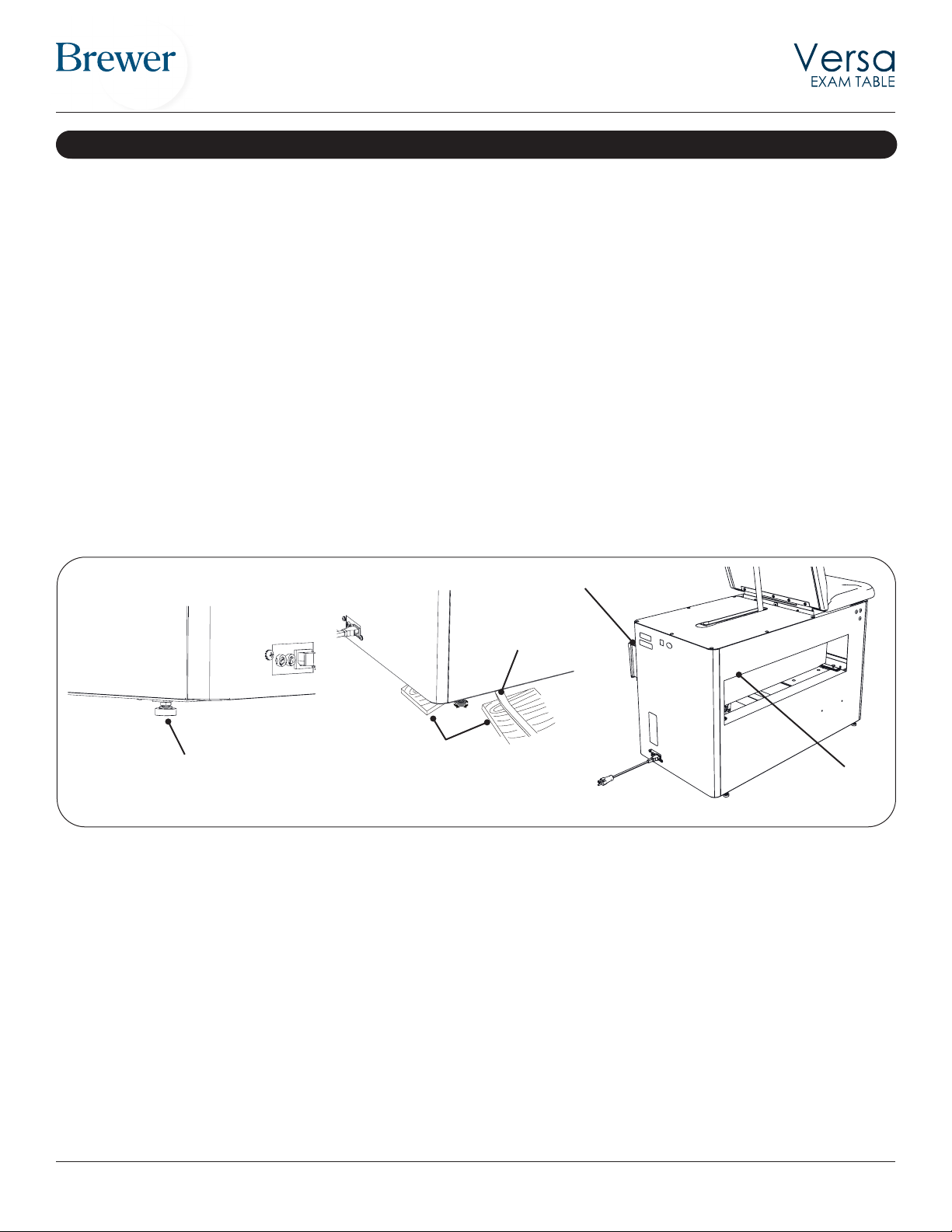
QR Code
Model Number and
Serial Number
Rating Label
Location
Figure 1. Model Number, Serial Number and
Rating Label Locations
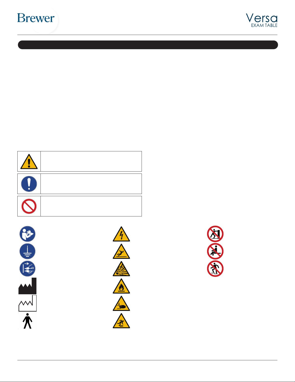
IMPORTANT INFORMATION