versa Quicktalk Go User manual

VERSA QUICKTALK GO SERVICE MANUAL
0
VERSA QUICKTALK GO SERVICE MANUAL

VERSA QUICKTALK GO SERVICE MANUAL
1
Table of Contents
1. Foreword...............................................................................................................................................3
2. Document Revision...............................................................................................................................4
3. Radio Information.................................................................................................................................5
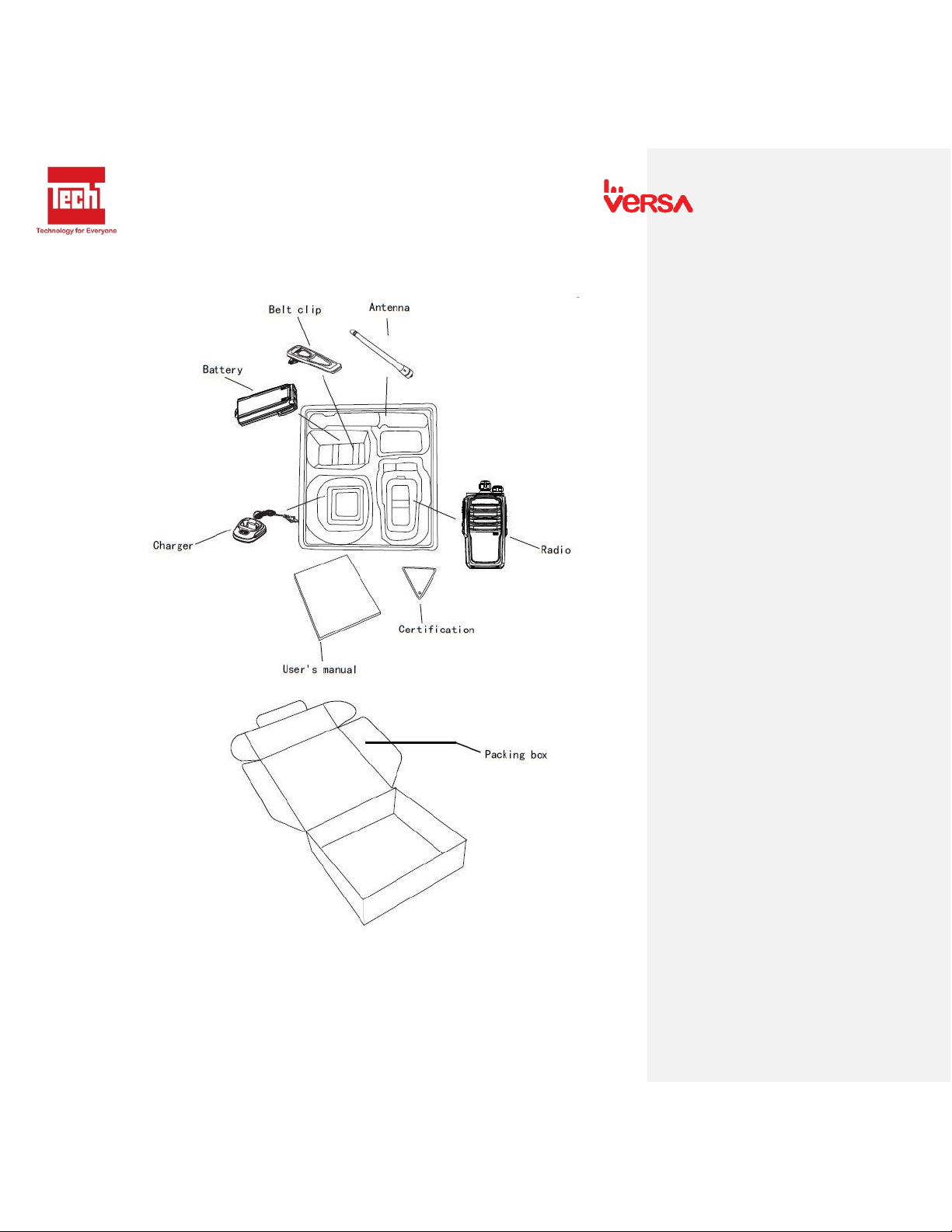
4. Package Layout ..................................................................................................................................... 6
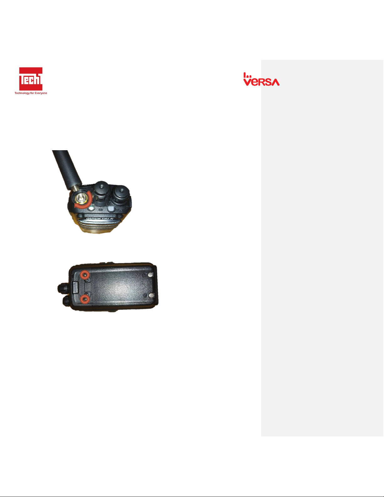
5. Parts of the Radio..................................................................................................................................7
6. Initial Assembly and Preparation..........................................................................................................8
6.1 Charging ........................................................................................................................................8
6.2 Battery Pack ..................................................................................................................................8
6.3 Antenna.........................................................................................................................................9
6.4 Belt Clip......................................................................................................................................... 9
6.5 Earpiece (Optional) .......................................................................................................................9
7. Basic Operation...................................................................................................................................10
7.1 Power on and Adjust volume knob.............................................................................................10
7.2 Channel selector knob ................................................................................................................10
7.3 PTT button...................................................................................................................................10
7.4 Monitor button ........................................................................................................................... 11
7.5 Lamp button................................................................................................................................ 11
8. Features ..............................................................................................................................................12
8.1 Voice Prompt ..............................................................................................................................12
8.2 Jacklight.......................................................................................................................................12
7.3 CTCSS/DCS.........................................................................................................................................12
7.4 Channel Scan.....................................................................................................................................12
7.5 Time-Out-Timer (TOT).......................................................................................................................12
7.6 Low Power Alarm..............................................................................................................................12
7.7 Squelch Level Adjustment.................................................................................................................12
7.8 High/Low Power Selection................................................................................................................12

VERSA QUICKTALK GO SERVICE MANUAL
2
7.9 Dual Watch Operation ......................................................................................................................12
9. Radio Assembly and Disassembly.......................................................................................................13
9.1 Assembly and Disassembly .........................................................................................................13
9.2 Housing .......................................................................................... Error! Bookmark not defined.
9.3 Board and Metal Case.................................................................... Error! Bookmark not defined.
9.4 Battery............................................................................................ Error! Bookmark not defined.
10. Quality Check ..................................................................................................................................18
10.1 Physical Appearance ...................................................................................................................18
10.2 RF Testing....................................................................................................................................18
10.3 Battery and Charger....................................................................................................................18
10.4 Radio Check.................................................................................................................................18
11. Schematic Diagram ......................................................................................................................... 19
12. Block Diagram .................................................................................................................................20
12.1 Front Board .....................................................................................................................................20
12.2 Back Board ......................................................................................................................................21
13. Troubleshooting and Repair..................................................................................................................22
13.1 External Parts..................................................................................................................................22
13.2 Internal Parts...................................................................................................................................23
14. Reprogramming ....................................................................................................................................25
14.1. Initial Setup ....................................................................................................................................25
14.1.1. General Requirements............................................................................................................25
14.1.2. How to install Quicktalk Pro programming software..............................................................25
14.1.3. Install Prolific USB to Serial Comm Port..................................................................................29
14.2. Radio Programming ....................................................................................................................... 31

VERSA QUICKTALK GO SERVICE MANUAL
3
1. Foreword
SCOPE OF THIS MANUAL
This manual is intended for use by experienced technicians
familiar with similar types of commercial grade communications
equipment. It contains all the required service information for the
equipment and current released data.
NOTE BEFORE USING
-DO NOT transmit until all RF connectors are verified secure and
any open connectors are properly terminated.
-SHUT OFF and DO NOT operate this equipment near electric
detonator caps or in an explosive atmosphere.
-This equipment should be serviced by a qualified technician
only.

VERSA QUICKTALK GO SERVICE MANUAL
4
2. Document Revision
DOCUMENTED BY
DESCRIPTION
DATE
Winston Yves L. Esguerra
Initial Release
March 2020

VERSA QUICKTALK GO SERVICE MANUAL
5
3. Radio Information

VERSA QUICKTALK GO SERVICE MANUAL
6
4. Package Layout

VERSA QUICKTALK GO SERVICE MANUAL
7
5. Parts of the Radio

VERSA QUICKTALK GO SERVICE MANUAL
8
6. Initial Assembly and Preparation
6.1 Charging
Before charging the battery, make sure that the transceiver has been turned OFF. To charge the
battery, plug in to AC outlet (110-240Vac) and insert the bottom of the transceiver (with the
battery) into the charger. Orange LED light on the charger indicates that the battery is charging.
Green LED light indicates that the battery is fully charged. The battery reaches its maximum
capacity after 2 to 3 charging cycles.
Note: The battery may be charged either attached or removed from the transceiver. Never
charge the battery at temperature below -10°C (14°F) or above 35°C (95°F).
6.2 Battery Pack
To Attach: Fit the battery at the back of the transceiver and slide the battery. Click sound
indicates that the battery is locked.
To Remove: Make sure the radio is turned OFF. Press down the battery latch at the top of the
belt clip.

VERSA QUICKTALK GO SERVICE MANUAL
9
6.3 Antenna
Connect the antenna to the antenna connector then turn the antenna clockwise to install and
turn counter clockwise to remove antenna.
6.4 Belt Clip
Fit the belt clip at the back of the transceiver. Screw the belt clip.
6.5 Earpiece (Optional)
Open the earmic cover located at the left side of the transceiver. Connect Earpiece.

VERSA QUICKTALK GO SERVICE MANUAL
10
7. Basic Operation
7.1 Power on and Adjust volume knob
- Turn the Power/ Volume knob clockwise. Beep sound indicates that the power is on.
7.2 Channel selector knob
- Rotate CHANNEL knob to choose desired channel. Up to 16 Channels.
7.3 PTT button
- To make a call, Press PTT. Keep mouth 3-4cm away from mic when speaking.
- Release PTT button to receive signals.
- Light Indicator: Steady Red when Transmitting / Steady Green when Receiving.

VERSA QUICKTALK GO SERVICE MANUAL
11
7.4 Monitor button
- When pressed, disable the CTCSS/DCS Code.
- To adjust the sound, Press MON and rotate the Power/ Volume to desired level.
7.5 Lamp button
- Press to turn jacklight ON. Press again to turn jacklight OFF.
Commented [MSG1]: Show MON button

VERSA QUICKTALK GO SERVICE MANUAL
12
8. Features
8.1 Voice Prompt
- You could set a voice prompt in English using PC programming software.
- Voice prompting when selecting channel.
8.2 Jacklight
- Mini flashlight between Channel and Power knob.
7.3 CTCSS/DCS
- Reduces the interference by adding a low frequency.
7.4 Channel Scan
- Scan Channel 1 to 16.
7.5 Time-Out-Timer (TOT)
- Limit the transmission period 0 to 600 seconds.
7.6 Low Power Alarm
- Audio prompt when the battery is low.
7.7 Squelch Level Adjustment
- Adjust the receiver sensitivity.
7.8 High/Low Power Selection
- Adjust the output power of the radio to 1W or 2.5W.
7.9 Dual Watch Operation
- Scan channel 16 and 1 selected channel.

VERSA QUICKTALK GO SERVICE MANUAL
13
9. Radio Assembly and Disassembly
9.1 Assembly and Disassembly
1. Remove antenna. Turn antenna counter clockwise.
2. Remove the battery. Press down the battery latch at the top of the belt clip then pull
the battery.
3. Remove Power/ Volume Knob and Channel Knob. Pull the knob.

VERSA QUICKTALK GO SERVICE MANUAL
14
4. Remove the 2 screwson the metal body. Unscrew by turning counter clockwise.
5. Remove the metal body from the housing. Pull up the metal body using chassis
remover.
6. Remove the round nut screw. Using round nut screwdriver, turn counter clockwise to
remove.

VERSA QUICKTALK GO SERVICE MANUAL
15
7. Remove the screw from the board. Turn counter clockwise to unscrew.
8. Pull mainboard from the metal body.

VERSA QUICKTALK GO SERVICE MANUAL
16
9.2 Exploded View

VERSA QUICKTALK GO SERVICE MANUAL
17

VERSA QUICKTALK GO SERVICE MANUAL
18
10. Quality Check
10.1 Physical Appearance
-Check physical appearance of the radio.
-Housing
-Knobs
-Battery Charger
-Belt clip
-Buttons
-Antenna
10.2 RF Testing
-Measure maximum and minimum receive sensitivity, TX power and VSWR
Test: Maximum and Minimum RX sensitivity, TX power and VSWR
Test Objective: The purpose of this test is to verify if the RX sensitivity, TX power and VSWR is
within the specifications.
Preliminary Steps:
For Receive: Set the frequency of the Signal Generator to the center frequency of Radio.
For Transmit: Set the maximum output power of the radio to the wattmeter.
RECEIVE
FREQUENCY
SENSITIVITY
REMARKS
MAX
MIN
TRANSMIT
FREQUENCY
TX POWER
VXWR
REMARKS
10.3 Battery and Charger
Test: Battery and Charger Voltage Measurement
Test Objective: The purpose of this test is to verify if the battery and charger voltage is within the
specifications.
Preliminary Steps:
For Battery: Set the battery specification to the battery analyzer.
For Charger: Set the multitester to Vdc.
OHMTEST
VOLTAGE
REMARKS
BATTERY
ADAPTOR
CHARGER
REMARKS
CHARGER
10.4 Radio Check
-Test short range communication

VERSA QUICKTALK GO SERVICE MANUAL
19
11. Schematic Diagram
Table of contents
Other versa Two-way Radio manuals