2 INSTALLATION
WARNING! Arc flash and electric shock hazard. Open all local and remote electric power supply
disconnect switches, verify with a voltmeter that power is Off and wear personal protective
equipment per NFPA 70E before working within the electrical control enclosure. Failure to
comply can cause serious injury or death.
WARNING! Risk of electric shock. Can cause equipment damage, injury or death.
Open all local and remote electric power supply disconnect switches and verify with a voltmeter
that power is off before working within any electric connection enclosures.
Service and maintenance work must be performed only by properly trained and qualified
personnel and in accordance with applicable regulations and manufacturers’ specifications.
Opening or removing the covers to any equipment may expose personnel to lethal voltages
within the unit even when it is apparently not operating and the input wiring is disconnected
from the electrical source.
NOTICE
Risk of improper installation. Can cause equipment damage.
Only a qualified service professional should install these products. We recommend that a
Vertiv™ technician perform the installation in large UPS system. Contact Vertiv™ at
https://www.vertivco.com/en-us/support/.
NOTICE
Risk of duplicate node IDs if two or more Liebert IntelliSlot cards are installed. Can cause
network conflicts.
An internal networking conflict will occur within a device when multiple communication cards
with duplicate Node IDs are installed in the device.
Each IntelliSlot card must have a unique node ID. This will not be a problem if only one card is
installed on your system. Duplicate node IDs are easily averted with the procedure detailed in
Installing Multiple Cards in a System on page7.
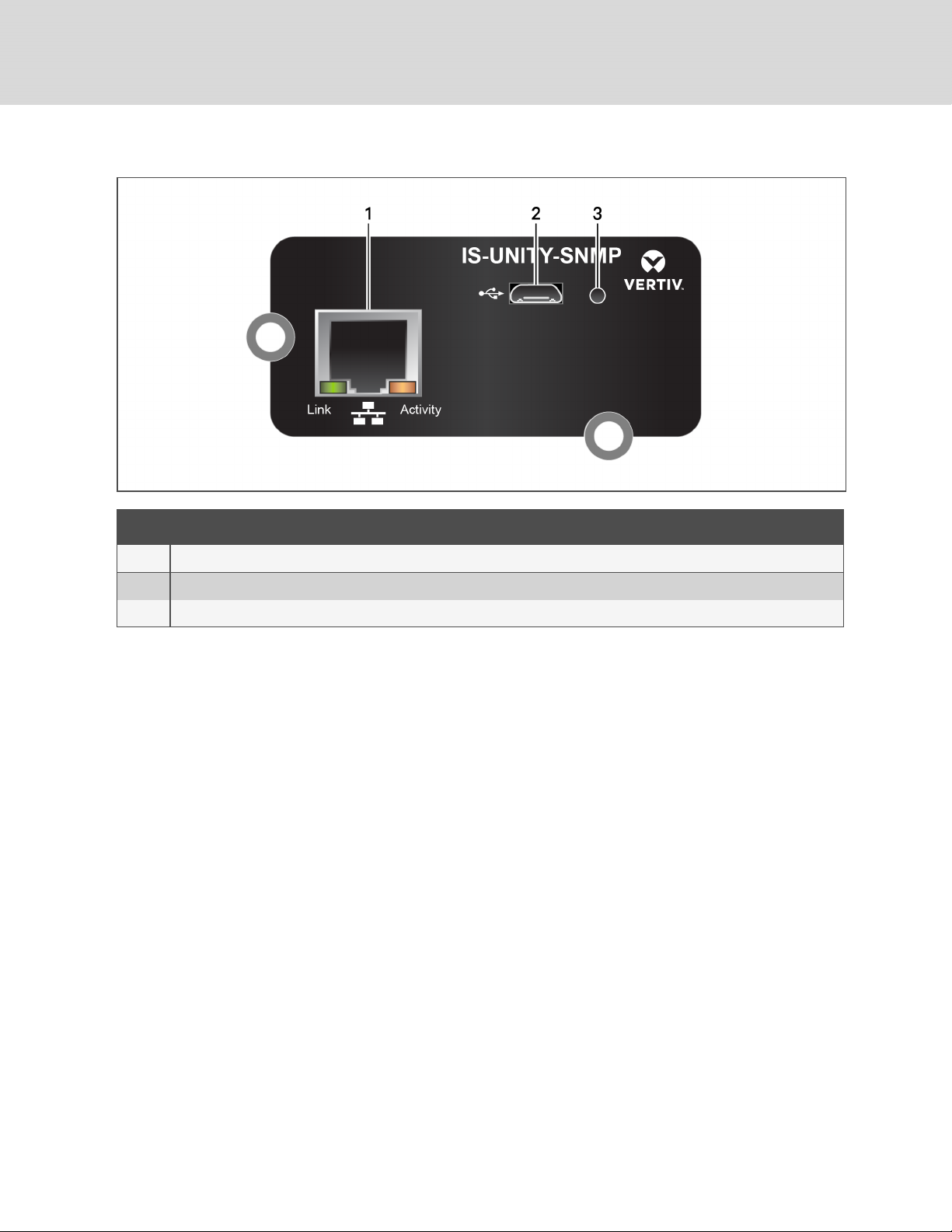
2.1 Installing the Card
The Unity card may be installed at the factory or field-installed.
To perform a field installation:
1. Find the IntelliSlot bay on your Liebert equipment—It may have a plastic cover.
2. Insert the card into the bay.
NOTE: The card will only fit one way in the bay because the circuit board is not centered on the
faceplate. The slot in the bay also is not centered.
3. Secure the card with the screws used for the cover plate.
2 Installation 3