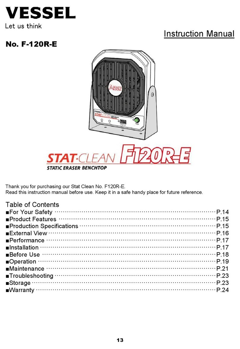
Vessel CF-600 User manual

静電気除去クロスフローファン
№ CF-600
─
〇ご使用の前に、この取扱説明書をお読みください。
〇お読みになった後はいつでも使用できるように大切に保管してください。
目 次
●安全にご使用いただくために ................................................................................................
................................
●製品の特長................................................................................................................................
................................
●製品の仕様................................................................................................................................
................................
●性能エリア図 ................................................................................................................................
................................
●外観図 ................................................................................................................................
................................
●各部名称と機能 ................................................................................................................................
................................
●設置 ................................................................................................................................
................................
●ご使用の前に ................................................................................................................................
................................
●運転 ................................................................................................................................
................................
●保守・点検................................................................................................................................
................................
●異常時の処置・保管................................................................................................
................................
●保証書 ................................................................................................................................
................................
─
取扱説明書
─
目 次
................................
.................... P.2
................................
...................... P.2
................................
...................... P.3
................................
................... P.3
................................
............................... P.4
................................
............ P.4
................................
.................................... P.5
................................
.................. P.6
................................
.................................... P.6
................................
........................ P.7
................................
.................................... P.9
................................
............................... P.10

2
安全にご使用いただくために
安全上のご注意
ご使用の前に、この「安全上のご注意」をよくお読みの上、正しくお使いください。
ここに示した注意事項は、危険の大きさにより次の2段階に区分して表示しています。
警告 取り扱いを誤った場合、死亡または重傷を負う可能性が想定される場合
注意 取り扱いを誤った場合、傷害を負う可能性および物的損害の発生が想定される場合
この記号は、「警告や注意」を促す内容です。
この記号は、行為を「禁止」する内容です。
この記号は、行為を「強制」する内容です。
警告
禁止 防爆を要求する環境、引火性の雰囲気の中で使用しないでください。防爆構造ではありま
せんので爆発や火災のおそれがあります。
禁止 製品を改造、分解することはおやめください。高電圧部品が入っており感電や故障、けがの
おそれがあります。
注意
禁止 急激に温度変化する環境や結露する場所では使用しないでください。故障のおそれがあり
ます。
水濡禁止
水、油、溶剤がかかるような場所や湿気の多い場所で使用しないでください。感電や故障
のおそれがあります。
禁止 除電、除塵以外の目的に使用しないでください。
禁止 本機には、指定の電源アダプタを使用するか、仕様を満たす電源を供給してください。火災
や感電の恐れがあります。
禁止 本体に落下等の衝撃を与えないように取り扱いにご注意ください。
禁止 本書を理解できるまでは、製品の設置、使用、保守をしないでください。
必ず守る 本書は簡単に参照できるように、製品のそばに保管してください。
■製品の特長
特長
コロナ放電式 ACタイプ…小型20kHz巻線トランスを採用、効率よくイオンが生成されます。
クロスフローファン…2つのファンが幅広く均一な風を送り出し、優れた除電性能を実現。軸流ファンに比
べ静音で快適な作業環境を実現します。風量は本体前面のボリュームで無段階に調整いただけます。
メンテナンス性…フロントカバーにスライド式のクリーニングブラシを装着しているため、いつでも針電極の
メンテナンスができます。掃除・交換が簡単なラフフィルターが本体底面に取付けられています。
安全設計…ファンモータ異常停止と高電圧出力停止の監視機能を装備しています。高圧電源に自動
出力停止機能を設けており短絡や過負荷時も安全です。ファンロック(FAN ALARM)・高圧異常(HV
ALARM)の出力端子を利用して、異常を報知させることができます。
低電圧入力…安全なDC24Vの低電圧入力です。自動機等の内部DC電源を利用することが可能で
す。
用途
静電気帯電によるトラブル防止や塵埃付着防止のための除電などにご使用ください。

3
本体
型式 :CF-600
イオン生成方式 :交流(20KHz)コロナ放電式
入力電源 :DC 24 V リップル(p-p)±10%以下
消費電流 :0.9A (max.)
寸法 :H157×W640×D170 (詳細は外観図参照)
質量 :約4.6 kg
風量 :2.5 m
3
/min 最大風量(ファン仕様書による)
騒音 :51.7dBA(本体正面から1mの距離で測定)
オゾン発生量 :0.05 ppm 以下
異常警告 :高電圧異常時(HV ALARM)赤LED、FANロック時(
FAN
保護機能 :ファンモータ回転監視機能(拘束検出)、高電圧出力
シャットダウン
検出)、電源ヒューズ3.15A
使用温度・湿度 :5~40℃ 35~65%RH(ただし、氷結、結露のないこと
)
保存温度・湿度 :0~60℃ 35~85%RH(ただし、氷結、結露のないこと
)
使用距離(推奨) :150~900 mm
設置場所 :屋内
除電時間 :1.5秒以下(正面300mm 風量最大)
イオンバランス :±10V以内(出荷時、測定距離300mm)
フィルター :ラフフィルター
材質 :本体:SPCC、スタンド:SUS304、放電針:インコネル
合金
標準付属品 :取扱説明書(本書)、ACアダプタ、ACケーブル、
クリーニングブラシ
済)、ゴムワッシャ2枚、スタンド2枚、角度調整ノブ2個
電源アダプタ AD24-IT-19
定格入力電圧 :AC 100 V – 240 V (50/60Hz)
定格出力電圧 :DC 24 V 1.9A
使用温度・湿度 :0~40℃ 10~85%RH(ただし、氷結、結露のないこと)
コード長さ :DC出力コード 約1.8m、AC入力コード 約1.8m
※測定値は当社測定環境によるものであり、使用環境により誤差が生
じることがあります
静電気除去性能
除電時間:帯電電位±1000Vを±100Vに減衰させるのに要する時間
帯電物までの距離と除電時間の関係
■製品の仕様
FAN
ALARM)赤LED
シャットダウン
機能(過負荷
)
)
合金
クリーニングブラシ
2個(本体取付
じることがあります
。
■性能エリア図

4
■外観図
外観図
■各部名称と機能
各部名称と機能
※外観図を参照
①ファン異常ランプ : ファンが停止し、拘束を検知した時に
FAN ALARM LED
②高圧異常LED : 高圧出力が停止した時にH.V. ALARM LEDが点灯
します
③風量調整 : ファンの風量を調整するときに使用します。無段階に
調整
④電源ランプ : 電源のON/OFFを確認できます。
⑤電源スイッチ : 電源のON/OFFを切替えることができます。
⑥ラフフィルター
フィルターカバー : ホコリの吸引を防ぐフィルターです。
⑦スタンド調整穴 : 本体の高さを調整するときに使用します。
⑧角度調整ノブ : 本体の角度を調整するときに使用します。
⑨スタンド : 本体を卓上や構造物に取り付けるときに使用します。
⑩DC24V電源端子 : 入力電源DC24V用の電源コネクタです。
⑪アラーム出力 : 警報信号を外部出力することができます。
⑫アース端子 : グラウンドアースに接地させるための端子です。
⑬クリーニングブラシ : 針電極に付着した埃やゴミを取り除く時に使用します。
⑭放電針 : 高電圧が印加され、イオンを生成します。
⑮イオン吹き出し口 : 放電針で生成されたイオンがここから送り出されます。
FAN ALARM LED
が点灯します。
します
。
調整
できます。

5
注意
必ず守る 振動の無い、強固で安定した所に固定してください。落下等
により
因となります。
必ず守る 設置環境は本体仕様の「使用温度・湿度」を守ってください。
製品
ります。
必ず守る 必ずアース線を接続してください。アースが接続されていないと
故障
あります。
禁止
次の場所では使用しないでください。爆発や火災、感電、故障
のおそれがあります
防爆を要求する環境や引火性の雰囲気
本体に著しい振動や衝撃が加わる場所
仕様に示された範囲を超える高温多湿な場所
結露する場所・急激な温度変化のある場所
ホコリ・粉塵・煙が多い場所・水・油・薬品等がかかる場所
強電界・強磁界が発生する場所
1. スタンドの取り付け
付属している角度調整ノブ、スタンド、ゴムワッシャを取り出し、スタンドに取り
付けます。
取り付ける順番は下記の通りになります(右図参照)。
“本体” ⇒ ”ゴムワッシャ” ⇒ ”スタンド” ⇒ ”角度調整ノブ”
2. 装置の固定
卓上で使用するとき
不安定な台の上などには置かないでください。落下により破損・故障の原因
になります
壁や構造物に取り付けて使用するとき
除電範囲を考慮して位置を決めてください。取り付け穴を利用して構造物やセル台
に
の角度調整ノブを緩めると本体の角度の調整が可能です。調整後は確実に
角度調整
品とワークの間に障害物が入らないようにしてください。底面のラフフィルターを塞
ぐような
ださい。※スタンドの底面には絶縁のためのゴム足を取り付けています。
スタンドをボルトで
外して使用してください
3. 電源の準備
ACアダプタを使用するとき
専用のACアダプタをご使用ください。
外部からの電源供給を行うとき
付属のACアダプタを使用せず、外部から電源を供給することができま
す。
図のようにモレックス製のコネクタで配線してください。
4. 接地
専用のACアダプタは、アース端子をもった電源コンセントへ接続してくだ
さい。外部からの電源供給を行うとき、グラウンドは必ず接地してくださ
い。これらが難しい場合、本体背面のアース端子を接地させてくださ
い。
■設置
により
、製品の破損や故障の原
製品
の劣化・故障の原因とな
故障
の原因となるおそれが
のおそれがあります
。
になります
。
に
固定できます。本体左右
角度調整
ノブを締めてください。製
ぐような
取り付けをしないでく
スタンドをボルトで
固定する際には取り

6
■ご使用の前に
注意
必ず守る 異常が見られたときは直ちに使用を中止してください。
禁止 高温のものに近づけたりしないでください。
禁止 放電針の接地短絡テストやスパークテストは決しておこなわないでください。イオンバランス
の性能に悪影響を与える場合があります。
1. 日常点検
使用する前に異常がないか点検してください。
メンテナンスは保守・点検のページを参照してください。
放電針の汚れ
ラフフィルターの汚れ
機器の損傷、部品のゆるみ
結露、水滴の付着など
クリーニングブラシの汚れ
故障や異常のあるときは、事故防止のため必ず販売店に点検修理を依頼してください。
■運転
運転
1. 運転開始
電源スイッチ(POWER)を[ I ]に合わせると、電源ランプが「緑色」に点灯し運転が開始されます。
※電源スイッチをONにした時(FAN ALARM)が瞬間的に「赤色」点灯することがありますが、異常ではありませ
ん。
2. 運転停止
電源スイッチ(POWER)を[ 〇 ]に合わせると、電源が切れ運転が停止します。
3. 風量調整
風量調整(FAN SPEED)ボリュームを、細めのマイナスドライバーなどで回すと、風量を無段階に調整できま
す。
※トリマーを強く回したり、調整限界以上に回そうとすると破損する可能性があります。
警告LED
1. 高圧異常
内蔵の高圧トランスユニットが負荷オーバーを検出し、出力をシャットダウンした場合、前面の「HV ALARM」
LEDが赤く点灯します。「HV ALARM」が点灯したときは、すぐ電源スイッチを押して電源を切ってください。放電
針に異物が付着している場合には、清掃して、再度電源を入れ、「HV ALARM」が点かないことを確認してくだ
さい。電源を入れたとき、再度「HV ALARM」が点灯する場合は、事故防止のため必ず販売店に点検修理を
依頼してください。

7
2. ファンアラーム
内蔵のファンがロックし異常を検出した場合、前面の「FAN ALARM」LEDが赤く
点灯
LEDが点灯したときは、すぐ電源スイッチを押して電源を切ってください。ファンに
異物
は、異物を取り出し、再度電源を入れ、「FAN ALARM」LEDが点灯しないことを
確認
たとき、再度「FAN ALARM」LEDが点灯する場合は、事故防止のため必ず販売店
に
さい。
警報信号を外部出力する場合
警報信号を外部出力することでお客様が取り付けられたライト等の外部報知装置を
作動
接続例
(別途電源を使用)
注意
電源を抜く
点検の作業時は電源プラグを抜いてください。感電や故障
のおそれがあります
禁止 洗剤や溶剤で拭いたりしないでください。ひび割れ・感電や故障
のおそれがあります
水濡禁止
水をかけないでください。感電や故障のおそれがあります。
点検する 点検は定期的におこなってください。
1. 本体の汚れ
本体の汚れは、乾いた柔らかい布で拭いてください。
開口部についたほこりなどは、掃除機で吸い取ってください。
シンナー等の溶剤類および洗剤は絶対に使用しないでください。
2. 放電針の掃除
長時間使用した場合、放電針に塵埃が付着し、除電性能の低下や塵埃の飛散の
原因
推奨:1週間に1度。
25mA(max)
24V(max)
25
24V(max)
■運転
点灯
します。「FAN ALARM」
異物
が噛み込んでいる場合
確認
してください。電源を入れ
に
点検修理を依頼してくだ
作動
させることができます。
■保守・点検
のおそれがあります
。
のおそれがあります
。
原因
となります。
25
mA(max)
24V(max)

8
■保守・点検
清掃手順
①電源スイッチをOFFにし、運転を停止してください。
②本体に装着しているブラシを左右
にスライドさせてブラッシ
ングします。
※クリーニングブラシに付着した塵埃は取り除いてください。
3. 針電極、クリーニングブラシの交換修理
針電極の交換修理
放電針に損耗、折れ、曲がりなどがある場合は、交換修理をお
買
い求めの販売店にご依頼ください。
クリーニングブラシの交換
クリーニングブラシの汚れが落ちない場合や毛先が広がってしまった場合は、
交換部品
にご依頼ください。
クリーニングブラシの交換手順
①CF-600の電源を切ります。
②クリーニングブラシを90度回転させて引き抜きます。
③クリーニングブラシを取り付ける時はその逆の手順で取り付けます。
注意
清掃する 放電針及びイオン吹き出し口の汚れにより、除電能力の低下や
塵埃
使用環境に合わせて必ず清掃または交換をおこなってください。
警告
禁止 針電極が破損している場合には、使用を中止し、交換、修理
してください
4. ラフフィルターの掃除/交換
設置場所やご使用状況によってラフフィルターの汚れ度合いは異なります。
除電性能
にはまず、ラフフィルターを掃除してください。ラフフィルター清掃の際は必ず運転を
停止
グをコンセントから抜くか、ACアダプタのコネクタを本体から抜いてください。本体が傷
んだり
ないよう布などを敷いて保護してください。
清掃手順
①フィルターカバーを外す。
②ラフフィルターを取り外す。
③流水で洗浄してください。
④洗浄後は水分を切り、十分に乾燥させてから装着
してください。
※ラフフィルターの汚れが落ちない場合や、傷みが激しい
ときはラフフィルターを交換してください(別売ラフフィル
ター CF-300Fをご使用ください)。
交換部品
ラフフィルター :CF-300F クリーニングブラシ :CF-
300B
交換部品
をお買い求めの販売店
塵埃
の飛散が発生します。
してください
。
除電性能
や風量が落ちてきたとき
停止
し、ACアダプタのプラ
んだり
、設備が傷んだりし
300B

9
■異常時の処置
注意
禁止
次のような場合は使用しないでください。火災や感電のおそれがあります。
落下や衝撃によって損傷している。
電源スイッチを押しても風が出ない。
コードが痛んだり熱くなったりしている。
コンセントへの差し込みがゆるい。
電源オフ 異常時には電源スイッチをオフにし、電源コネクタを抜いてください。
分解禁止 分解は絶対におこなわないでください。
不良や異常のままで使用した場合、製品の故障や事故の原因となりますので、すみやかに修理を依頼してくだ
さい。修理はお買い上げの販売店にご相談ください。
■保管
注意
禁止
次のような場所には保管しないでください。故障のおそれがあります。
本体に著しい振動や衝撃が加わる場所
仕様に示された範囲を超える高温多湿な場所
結露する場所
急激な温度変化のある場所
可燃性の溶剤や粉塵等、引火や爆発のおそれのある場所
ホコリ・粉塵・煙が多い場所
水・油・薬品等がかかる場所
強電界・強磁界が発生する場所
お願い
以下のような場合、事故防止のため必ず販売店に点検修理を依頼してください。
電源スイッチを入れても電源ランプがつかない。
ファンが回らない。
使用中本体を動かすと、風が出たり出なかったりする。
コードの一部が異常に熱い。
アダプタが異常に熱い。
使用時に異常な音や振動がある。
放電針先端でスパークが見られる(正常な動作ではスパーク放電は見られません)。

10
■保証書
お買い上げいただき誠にありがとうございました。
保証期間内に取扱説明書、本体ラベルなどの注意書きに従って正常な状態で使用していて故障した場合に
は、本書の記載内容に基づいて無償修理いたします。
修理・点検等は、お買い上げの販売店にご依頼ください。
保証期間中でも次のような場合には有償修理となります。
1)誤った使用方法、取り扱い上の不注意によって生じた損傷や故障
2)不当な修理や改造によって生じた損傷や故障
3)火災、地震、水害、落雷その他の天災地変、異常電圧などによって生じた損傷や故障
4)お買い上げ後の移動や輸送によって生じた損傷や故障
5)本書の紛失、所定事項の未記入または字句を書き換えられた場合
本書は再発行いたしませんので紛失しないよう大切に保管してください。
この保証書は、本製品の故障に対する無償修理または交換を保証するものであって、本製品の使用ま
たは使用不能によって生じた損害に対して当社が責任を負うものではありません。
この保証書は、明示した期間、条件のもとにおいて無償修理をお約束するものです。したがってこの保証
書によってお客様の法律上の権利を制限するものではございません。
型式 CF-600
保証期間 お買い上げ日より1年間 弊社では製品シリアルナンバーにて出荷日の管理を
おこなっております。
お客様 お名前
ご住所 〒
電話番号
販売店 店名/住所/電話番号

11
STATIC ERASER CROSS FLOW FAN
№ CF-600-E
Instruction Manual
Thank you for purchasing our Stat Clean No.CF600-E.
Read this instruction manual before use. Keep it in a safe handy place for future reference.
Table of Contents
For Your Safety········································· P.12
Product Features ······································ P.12
Product Specifications································ P.13
Performance ············································ P.13
External View ··········································· P.14
Names and Functions ································ P.14
Installation ··············································· P.15
Before Use ·············································· P.16
Operation ················································ P.16
Maintenance ············································ P.17
Troubleshooting & Storage·························· P.19
Instruction Manual
Read this instruction manual before use. Keep it in a safe handy place for future reference.

12
■
For Your
Safe
t
y
Safety Precautions
Carefully read these Safety Precautions before use. Observe the precautions indicated herein
to ensure safety.
Safety precautions in this instruction manual are categorized into two types by the degree of
danger associated with each of the followings. Based on danger analyses performed by
VESSEL, all precautions in this instruction manual are of the CAUTION level.
If the equipment is used in a manner not specified by the manufacturer, the protection provided
by the equipment may be impaired.
WARNING Indicates that improper handling can lead to serious injury or even death.
CAUTION(S)
Indicates that improper handling can lead to minor injury and property
damage.
This symbol indicates a WARNING or CAUTION.
This symbol indicates a prohibited action.
This symbol indicates a mandatory required action
WARNING
PROHIBITED
This product is NOT for explosion-proofing. DO NOT use in the situation requires
explosion-proof or flammable atmospheres. Explosion or fire may occur.
DO NOT
DISASSEMBLE
Do not disassemble this product. There is high voltage charged parts inside may
causes electrical shock, wound and / or malfunction of the product.
CAUTIONS
PROHIBITED
Do not place on environments with sharp changing of temperature. That may
cause breakdown or malfunction of this product.
DO NOT WET
Do not place on splash of water, oil, solvents. That may cause electric shock or
breakdown.
PROHIBITED
Do not use this product for anything other than static elimination or dust removal.
PROHIBITED
Do not use without included power supply or specified in the specifications. Those
may cause fire or electric shock.
PROHIBITED
Handle with care to avoid an impact. Keep away from falling.
REMEMBER Keep this instruction manual in a safe handy place for future reference.
■
Product Features
Product Features
AC-TYPE CORONA DISCHARGE…Compact 20KHz coil transformer inside.
CROSS-FLOW FAN INSTALLED…Wide and uniform air blow. Front cover designed for
performance. Low driving noise for the best working environment. Stepless airflow adjuster.
EASY MAINTAINANCE…A slide-type cleaning brush on the front cover for quick cleaning of
needle electrode. Easily to clean / replaceable rough filter installed on the bottom side.
SAFETY…Fan lock / HVT (high voltage transformer) overload are always watched. HVT has
automatic shutdown function when overload. Alarm sigs output terminal for external devices.
LOW VOLTAGE INPUT…Low voltage input 24V DC Power supply unit included. User side
power supply can be used by general connector (Molex®).
APPLICATIONS
Solution of troubles / problems caused by static electricity.

13
■
Product Specifications
Ionizer
Model : No.CF600-E
Ion generation method : High voltage AC (20KHz) corona discharge
Input voltage : 24VDC±10%
Consumption current : 0.9A (max)
Dimensions : H157×W640×D170(including stand)mm
Weight : 4.6㎏
Fan speed : 2.5㎥/min(Max. fan speed)
Noise emission : 51.7 dB(A) Max. fan speed(Measured at 1m)
Ozone generation : 0.05ppm or less
Warning output : High voltage alarm (Red LED),
Fan lock alarm(Red LED)
Protective function : Fan motor rotation monitoring function (Detecting rotation lock)
High-voltage output shut down function(overload detection)
Power fuse 3.15A
Working ambient
temperature / humidity :5~40℃/ 35~65%RH (No dewing or freezing)
Ambient storage
temperature / humidity :0~60℃ 35~85%RH(No dewing or freezing)
Distance from target
area(recommended) :150~900mm (Installation location: Non-hazardous indoor location)
Static electricity
removal time : Refer to the items in the performance chart.
Ion balance : Within ±10V (At 300mm ,at the time of shipment)
Air filter : Rough filter
Material
: Casing ... SPCC, Stand…SUS304
: Needle electrode... Inconel
Adapter No.AD24-IT19E
Rated input voltage :100-240V AC (50/60Hz) 1.9A
Rated output voltage :24V DC 1.9A
Working
temperature /humidity :0~40℃ 10~85%RH(No dewing or freezing)
*The measurement values were obtained under the VESSEL measurement environment, so error
could be induced depending on the operation environment.
■
Performance
Diagram of capacity area
Static electricity removal performance
Static electricity removal time: Time required to reduce charge electric potential from
±1000 V to ±100 V.
Relation between the distance to the charged object and the static electricity removal time
A
rea
A/F Max.
2.9m/s at
x, y = 0, 300mm
Time (Sec.) from
±1000V to ±100V
Equipment: Trek158
A/F Min.
2.5m/s at
x, y = 0, 300mm
Time (Sec.) from
±1000V to ±100V
Equipment: Trek158
<2Sec. <4Sec. <6Sec.
<8Sec.
<10Sec.
<2Sec. <4Sec. <6Sec.
<8Sec.
<10Sec.
<12Sec.

14
■
External View
■
Names and Functions
①Fan malfunction LED
: The FAN ALARM LED illuminates if the fan stops and fan lock is
detected.
②HVT* output warning
LED
: The H.V. ALARM LED illuminates if the high-
pressure
③Airflow adjuster : Adjusting the airflow. Stepless.
④Power LED : Check that the power is turned ON/OFF.
⑤Power switch : Used for turning the power ON/OFF.
⑥Rough filter
Filter cover
: A filter to prevent dust suction.
⑦Stand adjusting hole
: Used for adjusting the height of the body.
⑧Angle adjusting knob
: Used for adjusting the angle of the body.
⑨Stand
: Used for installing the body on a table or a structure.
⑩Power connector : A connector for input power of 24 V DC.
⑪Alarm output : Used for external output of alarm signals.
⑫Ground terminal : A terminal for grounding connection.
⑬Cleaning brush
: Used to remove dust or dirt adhering to the needle electrode.
⑭Needle electrode : High voltage is applied to generate ions.
⑮Ion air outlet :
The ions generated by the discharge needle are sent out from here.
*High Voltage Transformer
: The FAN ALARM LED illuminates if the fan stops and fan lock is
pressure
output stops.
: Used for installing the body on a table or a structure.
: Used to remove dust or dirt adhering to the needle electrode.
The ions generated by the discharge needle are sent out from here.

15
CAUTIONS
REMEMBER
Install CF600
-E securely.CF600-E can be damaged or
malfunction
dropped.
REMEMBER Install CF600-E on environments
withstanding the product specification
Adverse environments cause product deterioration and breakdown.
REMEMBER Be sure to connect the grounding wire.
A failure may result if this unit is not
properly grounded.
PROHIBITED
Do not useCF600-E base on following environments.
Adverse environments can result in explosion, fire, electric shock and accident.
*Where explosion-proofing is required.
*Where flammable atmospheres found.
*Where temperature and humidity are outside specified
ranges
*Where dewing or sharp temperature fluctuations occurs.
*Where there is heavy dust or smoke.
*Where possibly wet by water, oil, chemicals, etc.
*Where strong electric or magnetic fields are generated.
1. Attaching the stand
Attach the angle adjusting knob, stand, rubber washer, and stand to
the body.Assembling order(shown in the figure).
Body ⇒Rubber washer ⇒Stand ⇒Angle adjusting knob
2. Fix the product
When Used on a Desktop
CF600-E can be used on the desktop. Do not locate on unstable tables, etc.
damaged and malfunctioned if it falls.
When Mounted on a Wall or Structure
Select a location and height in consideration of CF600-E
's static electricity removal range
information regarding the static electricity removal range, refer to
the section
Use the mounting holes in the bottom of the stand
to secure it to the structure or cell base
the dimension drawing, refer to the section Exterior view).
The angle can be adjusted using the angle adjust
ing knob located on the left and right sides of
the stand. Securely tighten these knobs after confirming the angle.
Do not install this unit in dusty, hot or humid places or where possibly wet by water and
Keep objects from getting in-between CF600-E and the target area.
Before installing CF600-E, check the strength of supporting structure.
3. Supply power
Insert the included special AC adapter connector into the jack on the back o
f
the body.
User-side power supply
Power can be externally supplied to the unit without using
the provided AC
adapter. Carry out wiring with a Molex connector as shown in the figure.
Power Supply Adapter
Use the power adapter(AD24-IT19E)
which is specifically designed for use
of CF600-E. The AC adapter plug is a 2-pronged plug.
Connect this to a
power outlet that has a ground terminal.
4. Connection of grounding wire
Plug this unit into a power receptacle which has a ground terminal.
Be sure to connect the ground connector. If
no such power receptacles are
available, ground the unit with a wire
connected to the ground terminal of the
unit.
■
Installation
malfunction
ed if it is
withstanding the product specification
.
Adverse environments cause product deterioration and breakdown.
A failure may result if this unit is not
Adverse environments can result in explosion, fire, electric shock and accident.
ranges
.
CF600-E can be
's static electricity removal range
(For
the section
Performance).
to secure it to the structure or cell base
(For
ing knob located on the left and right sides of
Do not install this unit in dusty, hot or humid places or where possibly wet by water and
oil.

16
■
Before Use
CAUTIONS
REMEMBER If noticing anything strange, stop using this product immediately.
PROHIBITED Keep away from sources of heat.
PROHIBITED Do not test the electrode wires for grounding, short-circuiting or sparking. These
tests can adversely affect ion balance.
1. Daily Checks
Check CF600-E for inspection before use. Refer “Maintenance” pages.
Dust on electrodes
Contamination of the front cover
Dirty filter
Disconnection of the grounding wire
Loose connector
Damaged or loose parts
Adhering condensation or water droplets
Dust on cleaning brush
If damage or trouble is detected, contact the supplier for servicing.
■
Operation
1. TURNING ON THE UNIT
Turn the power switch (POWER) to the [I] position. The power light illuminates, and the operation will
start.
2. TURNING OFF THE UNIT
Turn the power switch (POWER) to the [O] position. The power light goes off and the operation will
stop.
3. AIRFLOW ADJUSTMENT
The airflow can be adjusted continuously by turning the airflow adjustment (FAN SPEED) rotary
control using a thin flat-tip screwdriver.
ALARM LED
1. H.V. ALARM
When the integrated piezoelectric transformer detects overload and shuts down the output, “HV
ALARM” LED on the front face lights up and the operation is stopped. If the alarm lights up,
immediately disconnect the connector to shut off the electric power. If a foreign matter adheres on the
discharge needle, clean the needle and turn on the power again to check that the alarm does not light
on. If the alarm lights up again when turning on the power, always ask the dealer for the inspection
and repair to prevent accidents.

17
2. FAN ALARM
The "FAN ALARM" LED, which is located on the front face, illuminates in red if the built
locked and a malfunction is detected.
When the "FAN ALARM" LED illuminates, immediately press
the power switch to the OFF position.
If a foreign object is caught in the fan, remove it and turn the
power switch to the ON position again to see if the "FAN ALARM" LED does not illuminate.
"FAN ALARM" LED illuminates again when the power is turned on, always have the
and repaired at the dealer to prevent an accident.
When alarm signal is output externally
With external output of alarm signal, warning devices such as lamps can be activated.
Connection Example
CAUTIONS
UNPLUG
POWER CABLE
Before making checks, unplug the power cable. Working with the power on can
result in electric shock and breakdown.
PROHIBITED Do not wipe with detergent or solvent. It may cause
cracking and
shock or breakdown.
DO NOT WET
Do not wet. Contact with moisture can result in electric shock or breakdown.
CHECK Periodically check.
1. Casing Cleaning
To clean the casing, wipe with a dry soft cloth. Suck up dust from opening
section
cleaner. Do not wipe it with solvents such as thinner, or detergent.
2. CLEANING THE NEEDLE ELECTRODE
When the unit is used for a long period of time, dust or dirt adheres to the needle electrode, which
causes the deterioration of antistatic performance or dust/dirt dispersion.
Recommendation: needle electrodes shall be cleaned a week.
25mA(max)
24V(max)
25mA
(max
24V(max)
■
Operation
The "FAN ALARM" LED, which is located on the front face, illuminates in red if the built
-in fan is
When the "FAN ALARM" LED illuminates, immediately press
If a foreign object is caught in the fan, remove it and turn the
power switch to the ON position again to see if the "FAN ALARM" LED does not illuminate.
If the
"FAN ALARM" LED illuminates again when the power is turned on, always have the
unit inspected
With external output of alarm signal, warning devices such as lamps can be activated.
Before making checks, unplug the power cable. Working with the power on can
cracking and
result in electric
Do not wet. Contact with moisture can result in electric shock or breakdown.
section
s with a vacuum
When the unit is used for a long period of time, dust or dirt adheres to the needle electrode, which
■
Maintenance
(max
)

18
Cleaning procedure
1) Turn the power switch to the OFF position to stop the
operation.
2) Slide the brush installed on the unit to both
ends to clean
the needle electrode.
* Remove dust adhering of cleaning brush.
3. REPAIRING OR REPLACING THE
NEEDLE ELECTRODE
If the cle
aning brush becomes extremely dirty or the needle
electrode is damaged, broken or bent, the components
must be replaced.
For repair and replacement of the parts,
contact the dealer where the product was purchased.
CAUTION
CLEANING
If the needle electrode or Ion air outlet
is dirty, it could lower the static erasing
performance or cause dust to fly around. Be sure
to clean the contaminated parts
according to your service condition.
WARNING
PROHIBITED
If HV ask us to have it replace the needle electrode unit
is broken or dropped out,
stop the operation and replace it with a new one. It
can lead to an electric shock
or injury.
4. Filter cleaning/replacement
Contamination degree of the filter depends on installation place and usage conditions.
erasing function or airflow decreases, clean the filter first. During the filter cle
aning, stop the
operation, pull out the AC adapter plug from the receptacle or the AC adapter connecter from the
body.
Spread a cloth or the like on the table to protect the body or the devices from the damage.
Cleaning procedure
①Remove the filter cover.
②Remove the filter.
③Rinse the filter with running water.
④After the rinse, drain excess water and dry the
filter thoroughly before the installation.
*If filter contamination cannot be removed or damage
is serious, replace the filter (Use the optional filter
CF-600F).
Accessories
Rough filter:CF-300F Cleaning brush:CF-300B
■
Maintenance
is dirty, it could lower the static erasing
to clean the contaminated parts
is broken or dropped out,
can lead to an electric shock
Contamination degree of the filter depends on installation place and usage conditions.
If static
aning, stop the
operation, pull out the AC adapter plug from the receptacle or the AC adapter connecter from the
Spread a cloth or the like on the table to protect the body or the devices from the damage.

19
■
Troubleshooting
&
Storage
CAUTIONS
PROHIBITED
Do not useCF600-E in the following situations. It may result in fire or electric
shock.
Damaged by falling or shock
No air blow though the power switch of the eraser is in the ON position
Power code is damaged or hot
Power plug is loosely connected to electrical outlet
UNPLUG
POWER CABLE
If trouble occurs with CF600-E, turn the power switch OFF and unplug the power
cable.
Do not continue using the unit in improper or abnormal condition, or otherwise a product damage or
accident may result. If trouble occurs, promptly request servicing from your dealer.
CAUTIONS
PROHIBITED
Do not store in the following places. Adverse environments can cause product
breakdown.
Exposed to vibrations or shock
Temperature and humidity are outside specified ranges
Dewing
Sharp change of Temperature
Possibility of ignition or explosion of flammable solvents, dust, etc.
Heavy dust or smoke
Where possibly wet by water, oil, chemicals, etc.
Where strong electric or magnetic fields are generated
In the following cases, contact the supplier for servicing.
Power lamp does not light when the power switch is in the ON position.
No fan works.
Intermittent air blow when moving the product slightly.
Power cable is excessively hot.
Power supply unit is excessively hot.
Abnormal noises or vibrates.
Lighting / sparks at needle electrode tips (there must be NO SPARK in normal operation).

20
LIMITED WARRANTY:
VESSEL expressly warrants that for a period of one (1) year from the date of purchase, VESSEL
static erasers will be free of defects in material (parts) and workmanship (labour). Within the warranty
period, Defects occurring will be repaired or products will be replaced at VESSEL's option and
expense, if VESSEL receives notice during the warranty period. Defective products must be returned
to VESSEL Osaka Japan with proof of purchase date. And if your unit is out of warranty, VESSEL will
quote repair charges necessary to ship your unit freight prepaid to where you have originally
purchased.
WARRANTY EXCLUSIONS:
THE FOREGOING EXPRESS WARRANTY IS MADE IN LIEU OF ALL OTHER PRODUCT
WARRANTIES, EXPRESSED AND IMPLIED, INCLUDING FITNESS AND MERCHANTABILITY
AND FITNESS FOR A PARTICULAR PURPOSE WHICH ARE SPECIFICALLY DISCLAIMED.
The express warranty will not apply to defects or damage due to accidents, neglect, misuse,
alterations, operator error, or failure to properly maintain, clean, or repair products.
LIMIT OF LIABILITY:
This electronic static eraser uses high voltage corona discharge and should not be used in or near
flammable or explosive environments. In no event will VESSEL or any seller is responsible or liable
for any injury, loss or damage, direct or consequential, whether based in tort or contract arising out of
the use of or the inability to use the product. Fulfillment of VESSEL's warranty obligations will be
Customer's exclusive remedy and VESSEL's and Seller's limit of liability for any breach of warranty or
otherwise. Before using this unit, users shall determine the suitability of the product for their intended
use, and users assume all risk and liability whatsoever in connection therewith.
Model CF600-E
Warranty (1) year from the date of purchase
Customer Name
Address
Tel. No.
Dealer Name/Address/Tel. No.
17-25, Fukae-Kita 2-chome,
Higashinari-ku, Osaka 537-0001 Japan
Tel : +81 6 6976 7778 Fax : +81 6 6972 9441
URL : www.vessel.co.jp
Printed in Japan
Ver.3 Published on 2020.3.13
This manual suits for next models
1
Table of contents
Other Vessel Fan manuals
Popular Fan manuals by other brands

Vortice
Vortice NORDIK AIR DESIGN 140-17 Instruction booklet

Ortech
Ortech SDF200 quick start guide

Deta
Deta 4600 Installation instructions manual

Ruck Ventilatoren
Ruck Ventilatoren MPC D 30 Series Assembly instruction

enervent
enervent eWind Pegasos installation instructions

Broan
Broan XB50L installation guide

Progress Lighting
Progress Lighting AirPro P2586 installation manual

Trebs
Trebs Comfort Air manual

Rotheigner
Rotheigner Air Quiet 100NF Original instructions

Hunter
Hunter 50235 installation manual

Greenheck
Greenheck XG-5700 Installation, operation and maintenance manual

Monte Carlo Fan Company
Monte Carlo Fan Company 5LCR52 Series installation instructions