VHT Special 12 User manual

12-20 Watt Hand-Wired Vacuum Tube Guitar Amplier
User Manual
VHT SPECIAL 12/20RT

IMPORTANT SAFETY INSTRUCTIONS
1) Read these instructions.
2) Keep these instructions.
3) Heed all warnings.
4) Follow all instructions.
5) Do not use this amplifier near water.
6) Clean only with dry cloth.
7) Do not block any ventilation openings. Install in accordance with the manufacturer’s instructions.
8) Do not install near any heat sources such as radiators, heat registers, stoves, or other apparatus (including amplifiers)
that produce heat.
9) Do not defeat the safety purpose of the polarized or grounding-type plug. A polarized plug has two blades with one
wider than the other. A grounding type plug has two blades and a third grounding prong. The wide blade or the third prong
are provided for your safety. If the provided plug does not fit into your outlet, consult an electrician for replacement of the
obsolete outlet.
10) Protect the power cord from being walked on or pinched particularly at plugs, convenience receptacles, and the point
where they exit from the amplifier.
12) Unplug this amplifier during lightning storms or when unused for long periods of time.
13) Refer all servicing to qualified service personnel. Servicing is required when the amplifier has been damaged in any way,
such as power-supply cord or plug is damaged, liquid has been spilled or objects have fallen into the amplifier, the amplifier
has been exposed to rain or moisture, does not operate normally, or has been dropped.
14) The amplifier shall not be exposed to dripping or splashing and no objects filled with liquids, shall be placed on the
amplifier.
15) This amplifier shall be connected to a mains socket outlet with a protective earthing/ground connection.
16) The mains/power plug or amplifier coupler is the disconnect device which must remain readily operable.
WARNING: To reduce the risk of fire or electric shock, do not expose this amplifier to rain or moisture.
OVERVIEW....................................................1
FEATURES.....................................................2
CONTROL PANEL FUNCTIONS.....................3-4
REAR PANEL FUNCTIONS.............................5-6
TONE CONTROL GRAPHS.............................7-8
DEPTH CONTROL GRAPH...............................9
TEXTURE SWITCH GRAPH............................10
FX RETURN - DEPTH CONTROL GRAPH.........11
FX RETURN -TEXTURE SWITCH GRAPH........12
BOOSTCONTROLGRAPH...............................13
BLOCK DIAGRAM..........................................14
SCHEMATIC..................................................15
TECHNICAL SPECIFICATIONS......................16
TABLE OF CONTENTS

VHT SPECIAL 12/20RT
THE PEDAL-FRIENDLY AMP WITH SELECTABLE POWER RANGES
PLUS ALL-TUBE SPRING REVERB AND TREMOLO
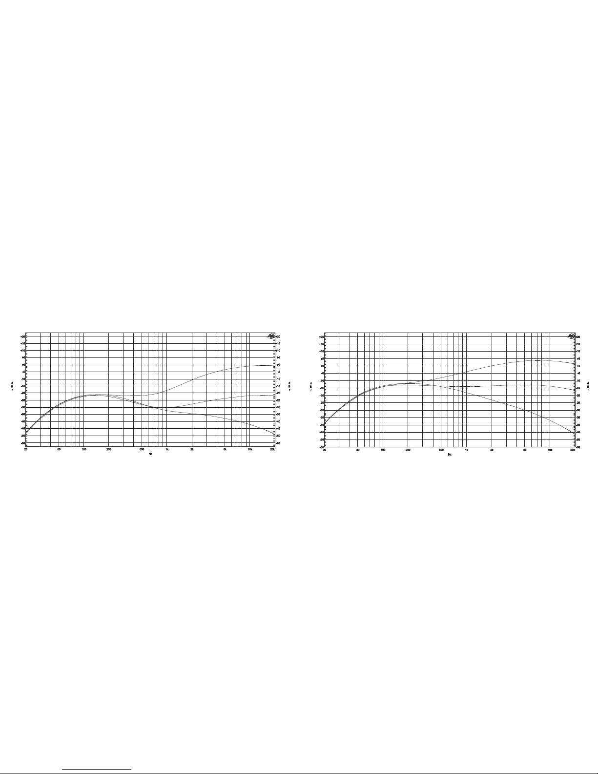
The VHT Special 12/20RT adds tube-driven spring reverb and tube tremolo to the pedal-friendly Special 12/20 platform. Like
the Special 12/20, the 12/20RT features a unique preamp specically designed to excel with pedals and multi-effects units,
with a pedal-friendly all-tube buffered effects loop with send and return level controls. And like the 12/20, the 12/20RT also
accepts a wide range of output tube types, with two power ranges complemented by an adjustable Watts control and a Pen-
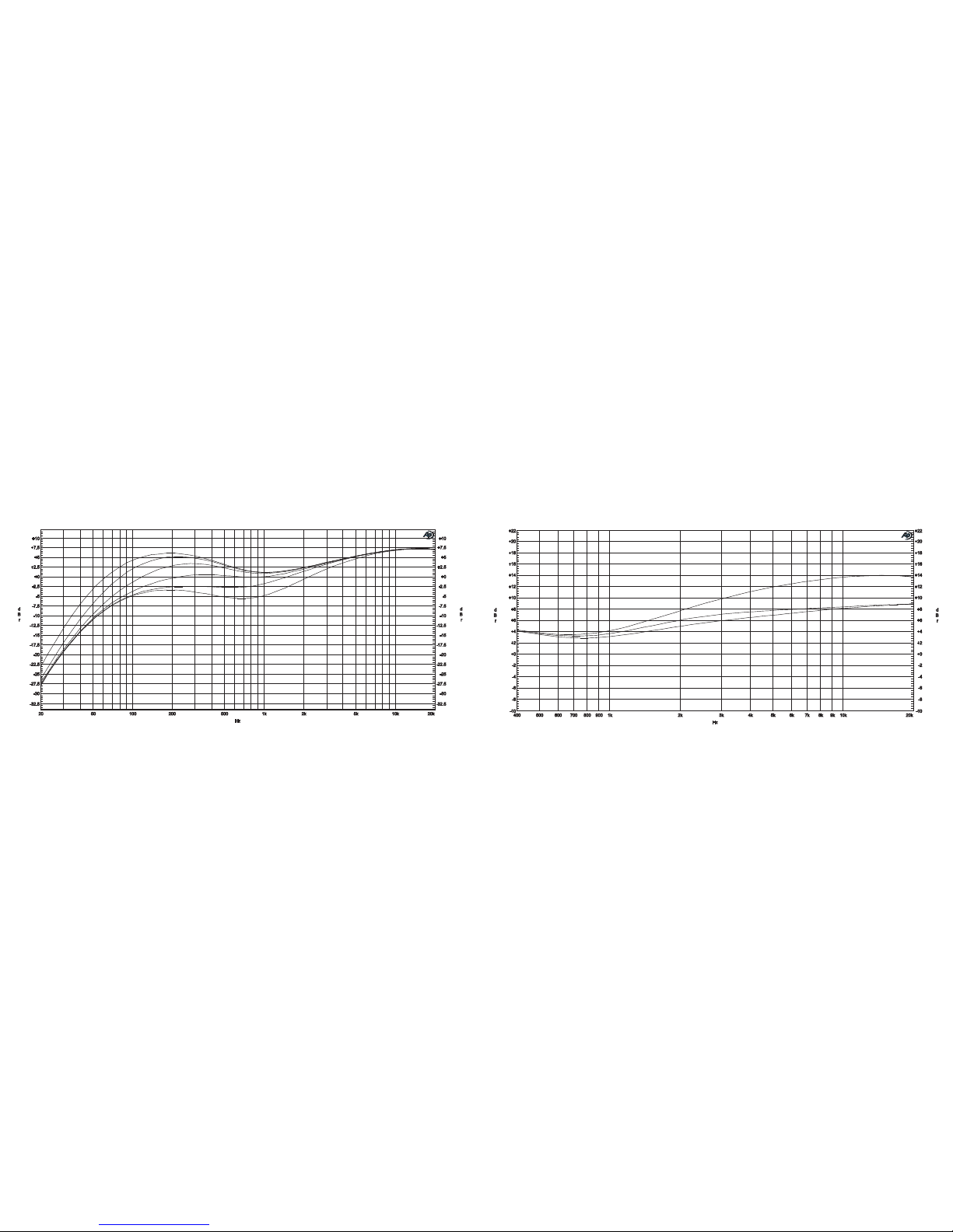
tode/Triode switch. The Special 12/20RT also features VHT’s unique Depth and Texture controls, a convenient built-in 9-volt
DC pedal power supply, and an international mains voltage selector switch.
Like the Special 12/20, the Special 12/20RT’s preamp was designed to bring the most out of every effects pedal and multi-
effects unit with enhanced clarity, detail, and controlled tube compression. Its low-impedance buffered effects-loop send can
effortlessly drive the most difcult pedals without tone or signal loss. Thanks to its variable send and return level controls,
the 12/20RT’s effects loop can accommodate a wide range of pedal, multi-effects units and rack effects. The 12/20RT’s Re-
verb, Tremolo, Depth and Texture controls are post effects loop, so multi-effects users can plug directly into the effect return
and still benet from the post-effects tube reverb and tremolo, while also ne-tuning the output stage characteristics with
the Depth and Texture controls.
To optimize the amp for a wide variety of output tubes, the VHT Special 12/20RT offers two output-power ranges; safely
located behind the rear panel, a special voltage range switch provides the proper voltages for 6V6 or EL84 output tubes (in
12-watt low-voltage/low-power mode). The high voltage 20-watt setting provides the ideal voltages for higher-power 6L6
or EL34 output tubes. The Special 12/20RT ships with a pair of 6V6 output tubes (VHT 6V6-to-EL84 socket adapters are
required for operation with EL84 tubes). In addition, the Special 12/20RT’s variable Watts control can reduce the maximum
output power to less than one watt for whisper-quiet volume levels.
VHT — THE WORLD LEADER IN AFFORDABLE HANDWIRED AMPLIFICATION
VHT SPECIAL 12/20RT FEATURES
Special Pedal-Friendly Preamp Design
Tube-Driven Effects Loop with Line Out Jack
Effects Send and Return Level Controls
9-Volt DC Pedal Power Supply
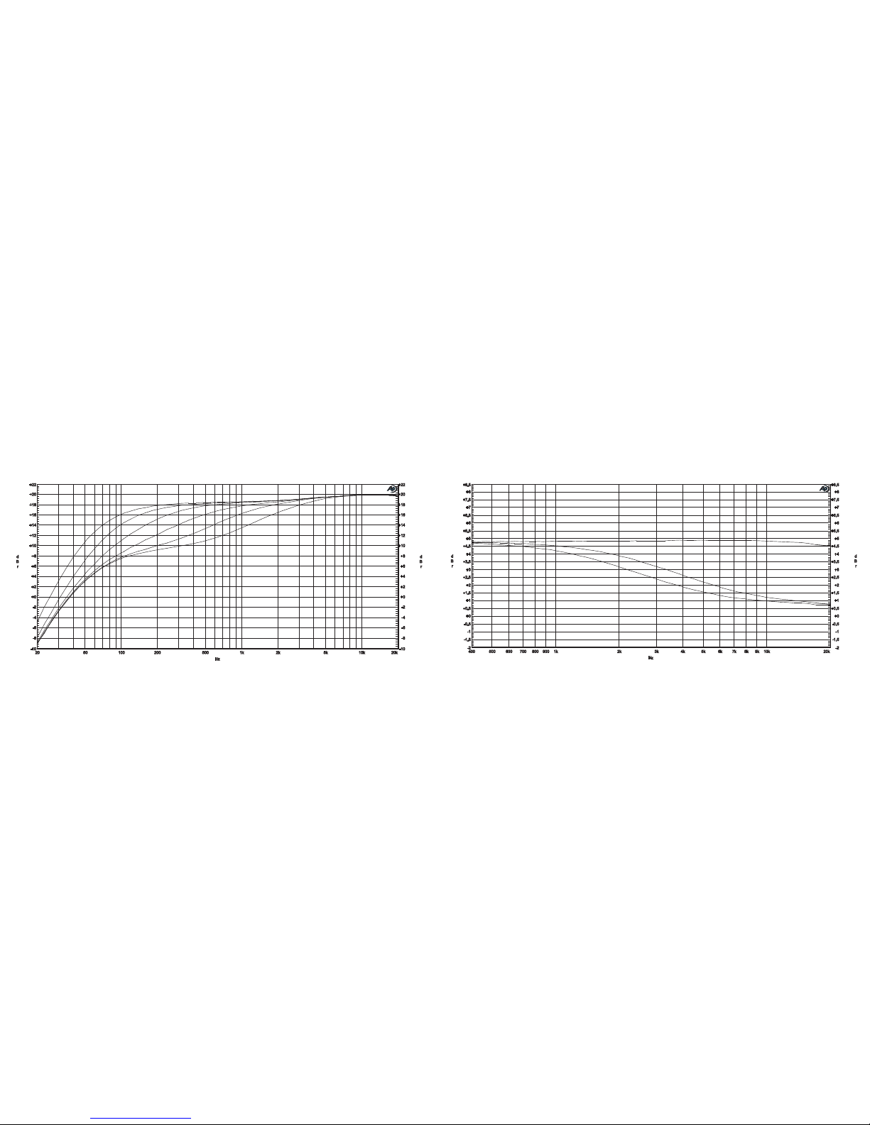
6V6 Tube-Driven Spring Reverb with Deep Switch
Tube Tremolo with Slow/Fast Range Switch
Switchable 12/20 Max Output
Variable Watts Control
Pentode/Triode Switch
6-Position Depth Control
3-Position Texture Switch
Footswitchable Push/Pull Boost
Switchable 4, 8 or 16 Ohm Speaker Outputs
International Voltage Switch
Four 12AX7 Tubes
One 6V6 Reverb Driver Tube
Two 6V6 Output Tubes
Accepts EL84 Output Tubes*
Also accepts 6L6 or EL34 Output Tubes
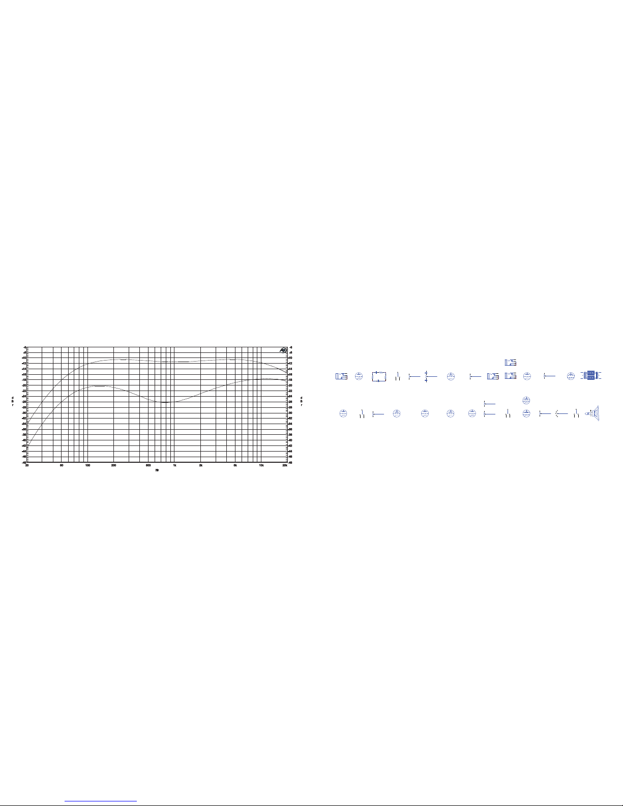
Mod-Friendly Handwired Eyelet-Board Construction
2-Button Reverb/Tremolo Footswitch (Included)
1-Button Boost Footswitch (Included)
12” VHT ChromeBack Speaker, 60-watt, 16 ohm (Combo Only)
*With VHT 6V6-to-EL84 Socket Adapters
2
1

CONTROL PANEL FEATURES CONTINUED
5. Depth Control: This 6-position rotary switch selects the output tubes’ low-frequency roll-off point. Set fully clockwise for
the deepest low-frequency extension. Lower settings (counterclockwise) expose more midrange texture and detail; the low-
est settings emphasize more presence and bite.
6. Texture Switch: This 3-position rocker switch selects the output’s high-frequency roll-off point and also inuences the
midrange texture. The middle position provides maximum top-end extension and the most harmonically complex texture;
the left position provides subtle high-frequency roll-off for a slightly smoother texture; the right position rolls-off more high
frequencies for the smoothest texture.
7. Tremolo: This control adjusts the intensity and depth of the tremolo effect. The Tremolo can be switched on or off with
the 2-button Reverb/Tremolo footswitch.
8. Slow/Fast Switch: This switch selects the tremolo circuit’s range.
9. Speed: This control selects the tremolo speed.
10. Reverb: This control adjusts the intensity of the Reverb effect. The Reverb can be switched on or off with the 2-button
Reverb/Tremolo footswitch.
11. Pull Deep: Pull this knob to add more low-end depth to the reverb signal.
12. Tone Control: This control adjusts the balance of the high and low frequencies.
13. Volume Control: Turning this knob clockwise increases the preamp drive and overall sound level.
14. Pull Boost: Pull this knob to partially bypass the internal tone shaping/voicing circuitry, which boosts the preamp gain
and increases the midrange emphasis. This feature can also be accessed by the footswitch.
15. Input: Pedal-friendly 1-megohm input impedance.
4
SLOW/FAST
DEEP
12 13
6 8
1 2 3 4 579 14 15
10 11
1. Power Switch: This switch turns the amplier on or off.
2. Pentode/Standby/Triode: The Triode setting reduces the amplier’s maximum output power to approximately one-half
of the Pentode setting. Triode setting produces a richer and smoother tone, with earlier breakup than the Pentode setting.
The middle position is Standby mode.
3. Watts Control: The Watts control adjusts the output tube’s operating voltage and maximum output power. Maximum
output power ranges from less-than 1 watt (fully counterclockwise) to 12 or 20 watts (fully clockwise).
4. Jewel Light: This light will be illuminated when the Power Switch is in the On position; the jewel light will be off when
the Power switch is in the Off position.
CONTROL PANEL FEATURES
3

1 2 3 4 567
12AX7 12AX7 12AX7 12AX7
6V6 6V6 6V6 Internal Speaker
16 ohms
6L6, EL34
HIGH VOLT
6V6, EL84
LOW VOLT
8
REAR PANEL FEATURES REAR PANEL FEATURES CONTINUED
1. Foot Switch Jacks: Plug the 1-button Boost footswitch into the lower jack. Plug the 2-button reverb/Tremolo footswitch
into the upper button.
NOTE: THE BOOST FOOTSWITCH WILL ONLY FUNCTION WHEN THE VOLUME KNOB IS IN THE PULLED POSITION.
2. DC Out: Plug the included 9-volt DC power supply cable into this jack to power your pedal(s) or pedal board. The LED
will illuminate at all times when powered. If the LED is not illuminated, check the internal DC Out fuse.
3. Effects Loop Send and Return Jacks: The post-preamp Effects Loop can accommodate a wide range of effects. The
send level is dependent on the preamp gain. High preamp gain levels may overdrive some sensitive guitar-level effects ped-
als. The Return jack has a pedal-friendly 1 megohm input impedance.
4. Line Out Jack: The preamp Line Out is in parallel with the Effects Loop Send and Return jacks, it can be used to send a
tube-buffered low-impedance (unbalanced) signal to other equipment such as mixing consoles or other ampliers. Multiple
VHT Special 12/20RT, Special 12/20 or Special 6 Ultra ampliers can be linked by connecting the Line Out jack to the Effects
Return of the second amplier. Several Special series ampliers can be linked in this manner, with the rst amplier’s pre-
amp serving as the master preamp for all additional ampliers.
5. Impedance Selector: This 3-position slide switch selects the appropriate output impedance to match your speaker cabi-
net’s impedance.
6. Speaker Output Jacks: These two jacks are wired in parallel. The Special 12/20RT combo has a 16-ohm speaker that
is connected to the internal speaker jack. The combo’s speaker remains connected when using the external Speaker Output
jacks. When using the combo with an additional 16 ohm speaker cabinet, switch the Impedance selector to 8 ohms.
7. Power IEC Receptacle/Line Voltage Selector: Use the included power cord with this unit in accordance with the AC
line voltage and frequency ratings listed on this manual and rear panel of this amplier. Your amplier will ship with the cor-
rect voltage for your region; when traveling to different countries, remove the clear plastic protector and ip the switch to
the appropriate voltage. For lowest noise and safest operation, always provide the amplier with proper AC grounding.
8. 12/20-Watt High/Low Power Voltage Selector: Located behind the rear panel, this switch selects the appropriate
maximum voltage for each output tube type. Set it to the 20-watt High-Volt position when using 6L6 or EL34 output tubes.
Set it to the 12-watt Low Volt position when using 6V6 or EL84 output tubes. (EL84 output tubes require 6V6-to-EL84 tube
socket adapters.)
56

TONE CONTROL — NO BOOST
-55
+20
-50
-45
-40
-35
-30
-25
-20
-15
-10
-5
+0
+5
+10
+15
d
B
r
20 20k50 100 200 500 1k 2k 5k 10k
Hz
-55
+20
-50
-45
-40
-35
-30
-25
-20
-15
-10
-5
+0
+5
+10
+15
d
B
r
TONE CONTROL — PULL BOOST
-55
+20
-50
-45
-40
-35
-30
-25
-20
-15
-10
-5
+0
+5
+10
+15
d
B
r
20 20k50 100 200 500 1k 2k 5k 10k
Hz
-55
+20
-50
-45
-40
-35
-30
-25
-20
-15
-10
-5
+0
+5
+10
+15
d
B
r
7 8

DEPTH CONTROL — PREAMP INPUT (NO BOOST)
-32.5
+10
-30
-27.5
-25
-22.5
-20
-17.5
-15
-12.5
-10
-7.5
-5
-2.5
+0
+2.5
+5
+7.5
d
B
r
20 20k50 100 200 500 1k 2k 5k 10k
Hz
-32.5
+10
-30
-27.5
-25
-22.5
-20
-17.5
-15
-12.5
-10
-7.5
-5
-2.5
+0
+2.5
+5
+7.5
d
B
r
TEXTURE SWITCH — PREAMP INPUT (NO BOOST)
-10
+22
-8
-6
-4
-2
+0
+2
+4
+6
+8
+10
+12
+14
+16
+18
+20
d
B
r
400 20k500 600 700 800 900 1k 2k 3k 4k 5k 6k 7k 8k 9k 10k
Hz
-10
+22
-8
-6
-4
-2
+0
+2
+4
+6
+8
+10
+12
+14
+16
+18
+20
d
B
r
9 10

DEPTH CONTROL — EFFECTS RETURN INPUT
-10
+22
-8
-6
-4
-2
+0
+2
+4
+6
+8
+10
+12
+14
+16
+18
+20
d
B
r
20 20k50 100 200 500 1k 2k 5k 10k
Hz
-10
+22
-8
-6
-4
-2
+0
+2
+4
+6
+8
+10
+12
+14
+16
+18
+20
d
B
r
TEXTURE SWITCH — EFFECTS RETURN INPUT
-2
+8.5
-1.5
-1
-0.5
+0
+0.5
+1
+1.5
+2
+2.5
+3
+3.5
+4
+4.5
+5
+5.5
+6
+6.5
+7
+7.5
+8
d
B
r
400 20k500 600 700 800 900 1k 2k 3k 4k 5k 6k 7k 8k 9k 10k
Hz
-2
+8.5
-1.5
-1
-0.5
+0
+0.5
+1
+1.5
+2
+2.5
+3
+3.5
+4
+4.5
+5
+5.5
+6
+6.5
+7
+7.5
+8
d
B
r
11 12

Input Stage
Input Eects Loop Buer
Eects Return
Send Return
Line Out
Watts Texture Speaker
Pull Boost Volume Tone
Tone Stack
Depth
Send Level Return Level
Voltage Amplier
Cathode Follower
Phase Splitter
Output Tubes
Reverb Driver
Pull Deep ReverbReverb Return
Spring
Tremolo
Fast/Slow
6V6
6V6
6V6
12AX7 12AX7
12AX7 12AX7 12AX7 12AX7
12AX7
12AX7
Speed
Tremolo
BLOCK DIAGRAM
-48
-6
-46
-44
-42
-40
-38
-36
-34
-32
-30
-28
-26
-24
-22
-20
-18
-16
-14
-12
-10
-8
d
20 20k50 100 200 500 1k 2k 5k 10k
Hz
-48
-6
-46
-44
-42
-40
-38
-36
-34
-32
-30
-28
-26
-24
-22
-20
-18
-16
-14
-12
-10
-8
d
B
r
-48
-6
-46
-44
-42
-40
-38
-36
-34
-32
-30
-28
-26
-24
-22
-20
-18
-16
-14
-12
-10
-8
d
B
r
BOOST — ON/OFF
14
13

1 2 3 4 5 6 87
A
B
C
D
8
7654321
D
C
B
A
Title
Number RevisionSize
A3
Date: 21-Sep-2011 Sheet1 of 1
T
T NC
G NC
G
JK2
CLEAN
R2
33K
R1
1M
C2
101/500V
6
7
8
V1B
12AX7
C1
103/500V
R4
1K5
R3
100K
B+5
C4
221/500V Mica
C5
104/400V
C6
473/400V
R5
100K
R6
180K
R7
33K
R8
33K
R9
6K8
R10
68K
T
T NC
G NC
G
JK3
FOOT SWITCH
S1/VR2
1
2
3
VR1 1M
C7
471/500V Mica
C9
103/630V
Push/Pull Pot
Push = Closed (Clean)
Pull = Open (Boost)
1
2
3
VR2
1M
1
2
3
V1A
12AX7
R11
470KR12
1K5
R13
100K
R14
1K5
R15
1K5
C10
224/400V
T
T NC
G NC
G
JK4
SEND
T
T NC
G NC
G
JK5
RETURN
B+5
R23 3M3
R18
220K
R19
1K5
6
7
8
V2B
12AX7
B+4
C11
103/500V
C20
472/400V
Ceramic
Ceramic
CLEAN TONE
Ceramic
VHTSpecial 12/20RT
Rev1.0
C8
472/400V
T
T NC
G NC
G
JK6
LINEOUT
80mVAC
TP4
80mVAC
TP5
80mVAC
TP6
30mVAC
TP1
1V DC
TP2
65VDC
TP3
0.7VDC
TP7
R70
10K/3W
C52
47u/500V
C53
104/630V
R32
56K
R34
1K5
1
2
3
V5A
12AX7
B+3
C33
223/400V
C34
223/400V
R38
220K
R37
220K
R36
5K6
R54
1K 5W
D3 1N4007
D4
1N4007
S2
POWER SWITCH
RED
BROWN 0V
GREEN
GREEN
BLACK
BLACK
WHITE
WHITE
WHITE
YELLOW/GREEN
J3
J5
J4
J6
D1
IN4007
D2 IN4007
C43 8.2n/1KV
C44 8.2n/1KV
C46 8.2n/1KV
C45 8.2n/1KV
F1
T2A/250VSLO BLO
BLACK
T1
RT1
NTC(10R/5A)
NF72-10D15
AC
IEC
R62
220K
C47
100u/350V
R64
470KR65
100K
R66
100K
R69
33K/3W
C51
47u/500V
C49
47u/500V
C50
47u/500V
T2
RED
BLUE
BLACK 0ohm
B+1
YELLOW 4ohm
BROWN 8ohm
ORANGE 16ohm
1
2
3
VR8B
1M
G
DS
Q1
FQP9N90C
B+3
R67
10R 5W R68
1K 3W
ZD1
12V1W
B+2
R40
1M
R41
1M
R42
1M
R43
1M
R44
1M
R45
1M
12" 16 OHMS
S1A S1B S1C S1D S1E S 1F
C21
474/100V
C22
1u/100V
C24
4u7/63V
C25
10u/63V
C26
22u/63V
DEPTH
2P-6T ROTARY SWITCH
3
5
8
4
V6A
6V6GT
B+4
FILM FILM
B+1
T
T NC
G NC
G
JK7
EXT SPK1
T
T NC
G NC
G
JK8
EXT SPK2
320VDC
TP14
212V DC
TP18
218V DC
TP17
308V to 29V DC
TP15
303V to 29V DC
TP16
S4
C35
2u2/100V(I)
C36
3u3/100V(II)
TEXTURE
FILM FILM
R56
15R 10W
C57
0.1/630V
T
T NC
G NC
G
JK9
INTERNALSPK
S5
DP3T
4 OHM
8 OHM
16OHM
F3
T0.5A/250V
WATTS
BROWN
3
5
8
4
V7A
6V6GT
R39
5K6
R35
56K
R33
1M
R55
1K 5W
R46
470R 5W
B+2
F2
T8A/250VSLO BLO
V1
12AX7
V6
6V6GT
V7
6V6GT
V2
12AX7
29.2V DC
TP11
68VDC
TP13
294V DC
TP10
10V AC @ 8ohm
TP19
ON
ON
STBY
S3A
STB ON/ON
S3B
S3C
STBY
TRIODE
PENTODE
4 5 4 5 2 2
7 7
9 9
6.8V
12VC56
470u/16V
T
T NC
JK1
9V DC OUT
R73
100R
R74
100R
R72
220R
D10
LED(RED)
D5
1N4007
D6
1N4007
D8
1N4007
D7
1N4007
OUT
G
IN
U1
7809
R47
1M
R48
1M
R49
1M
R50
1M
R51
1M
R52
1M
S2A S2B S2C S2D S2E S 2F
C27
474/100V
C28
1u/100V
C30
4u7/63V
C31
10u/63V
C32
22u/63V
FILM FILM
R53
470R 5W
V3_8
V4_8
V3_8
V4_8
D9
IN4007
C42
0.1/630V
S6
EL34/6V6GT
ORANGE
YELLOW
265V
310V
17V
17V
100V
100V
S7
DP3T
234V
117V
100V
BLUE
WHITE
ORANGE
BROWN
RED
YELLOW
1
2
3
VR3
100KA
1
2
3
VR4
250KA
R17
33K
R16
1M
R28
100K
SEND
LEVEL
RETURN
LEVEL
121V DC
TP20
1
2
3
V4A
12AX7
6
7
8
V4B
12AX7
R31
100K
R30
1K5
C16 10PF
C13
103/630VR29 100R
B+5
V3
12AX7
4 5
9
R71
10K/3W
C54
47u/500V
C55
104/630V
B+5
212V DC
TP18
B+
0.7VDC
TP7
C12
4u7/63V
F4
T1A/250VSLO BLO
D11
LED (RED)
R75
220R
C23
2u2/63V
C29
2u2/63V
C48
100u/350V
R63
220K
R57
180K
R58
330K
R59
47K
R61
2K2
6
7
8
V5B
12AX7
1
2
3
VR6
B500K Speed
1
2
3
VR7
B250K Depth
C37
473/630V
C38
473/630V
C39
104/630V
C40
104/630V
C41
22uF/25V
S2B
Tremolo
R60
220K
B+3
0.6~1.6V
V5
6V6GT
2
7
V4
12AX7
4 5
9
R20
220KR21
470R 5W
C14
222/400V
C15
22uF/63V
Reverb
Transformer
B+2
Red
Blue
2.2V
3
5
8
4
V3A
6V6GT
R22
1K 5W
R24
100K
R27
220K
R25
220K
R26
1K5
1
2
3
V2A
12AX7
1
2
3
VR5
B100K Reverb
C17
332/630V
B+4
REVERB TANK
C18
4u7/63V
C3
4u7/63V
C19
4u7/63V
1
2
3
VR8A
A1M
S2A
Reverb
VR5-SW
Reverb DEEP
C17*
472/630V
R57
1M
FAST/SLOW
TECHNICAL SPECIFICATIONS
Name/Model: VHT Special 12/20 — 12-20 watt hand-wired vacuum tube
guitar amplier
Power Requirements & Consumption: 100/115VAC, 50/60Hz; 120VAC, 60Hz;
220/230/240/VAC, 50/60Hz
Maximum Output Power: 12-20 watts (depending on output tube type and Volt setting)
Speaker (combo only): One 12” VHT ChromeBack (60-watts, 16 ohms)
Amp Type: All-tube hand-wired push/pull cathode biased output stage
Tubes: Four 12AX7; three 6V6
Controls: Volume (with Pull-Boost), Tone, Reverb (with Pull-Deep),
Tremolo Speed, Tremolo Fast/Slow Range,
Tremolo Intensity and Depth, Texture, Depth, Watts,
Pentode/Triode, Effects Send Level, Effects Return Level,
High/Low Volts
Cabinet: Finger jointed birch plywood
Cosmetics: Black vinyl, white piping, and black grille cloth
Dimensions (H x W x D): Combo: 19’’ x 19.5’’ x 10.5” (475mm x 495mm x 265mm)
Head: 11” x 19.5’’ x 8.5’’ (280mm x 495mm x 215mm)
Net Weight: Head: 28 lbs. (12.5 KG)
Combo: 43 lbs. (19.5 KG)
16
15

LIMITED WARRANTY INFORMATION
This amplifier is warranted, to the original Purchaser, to be free from defects in material and workmanship for
a period of five (5) years, excluding the tubes and speaker, which are warranted for ninety (90) days, from the
original date of purchase.
The manufacturer shall, at its option, either repair or replace the defective product if the product is returned to
the original place of purchase. If any product returned is not defective within this warranty, the manufacturer
shall so advise the Purchaser and thereafter shall dispose of said product in accordance with the Purchaser’s
instructions and at the Purchaser’s cost. This warranty is not transferable by the Purchaser.
The warranty shall not apply to wearable parts, these items include, but are not limited to, amplifier knobs, feet, and
handles.
The warranty shall not apply, if the product has been misused or damaged as a result of neglect, abuse, alteration,
improper handling, unauthorized repair or modification, accident or causes external to the product, such as, but
not limited to, excessive heat or humidity.
The manufacturer’s sole and exclusive maximum liability for any claim by the Purchaser shall not exceed
the wholesale value of the product. In no event shall the manufacturer be liable for any indirect, incidental,
collateral, exemplary, or consequential damages of losses arising out of the Purchaser’s purchase of the product. The
above limitations may not apply in some states (U.S.), international regions or countries.
VHT
AMPLIFICATION
HANDWIRED IN CHINA
Other manuals for Special 12
1
This manual suits for next models
1
Other VHT Musical Instrument Amplifier manuals