Viavi Observer Gigastor GS-8P-384T Manual

GS-8P-384T
Hardware Installation
21 Jan 2020

2 — © 2020 Viavi Solutions (21 Jan 2020)
GS-8P-384T
GS-8P-384T technical specifications
The technical specifications for this product are shown below.
System -
Deployment Multi-10 Gb data center
Base storage 384 TB
Max storage 768 TB
Lights Out Management (LOM) Yes
Redundant OS drive Yes
OS drive hot swappable Yes
OS drive size 1 TB
RAID drive hot swappable Yes
RAID version 50
Rail kit (Model 22113260) Yes
Operating system Windows 2012 R2
Physical -
Height 20U (4 x 5U)
Width 19 in
Depth 26 in
Weight (mounted) 1416 lbs
Weight (handling) 80 lbs
Media -
Monitoring interfaces 8
Speed 1/10 Gb
Accepted transceivers 2SFP/SFP+
Performance -
Aggregate performance 40 Gbps
Power -
Redundant power supply Yes
Input frequency 50/60Hz
Input voltage 100V-240V Auto Select
Operational current (amps) 14.3A
BTU 5391 BTU/hr
Operational voltage 120V
Power dissipation (watts) 1716W
Relative humidity (non-
condensing)
20-80%
Temperature (operating) 50°F - 95°F / 10°C - 35°C
Temperature (storage) -4°F - 149°F / -20°C - 65°C
1. If applicable, mounted weight includes any rail kits.
2. SFP may be any of Copper 10/100/1000, 1Gb SX/LX. SFP+ may be any of
10Gb SR/LR. QSPF+ may be any 40Gb SR/LR/BiDi/Universal.
Parts list
Each appliance comes packed in a box or several boxes.
The boxes contain the various components necessary for a
successful installation.
The boxes are not numbered as listed here. The numbers merely
represent how many boxes you should expect and what is
contained in each one.
♦Box 1
●1 Head unit
●1 Rail kit
10-32 screws (4)
6mm screws (4)
Rails (2)
●2 Power supply cables
●1 Ethernet cable
●2 keys for lock
●1 USB drive containing restore image
●1 Product Activation Information envelope
containing the product license
●1 Quick Start Guide
●SFP transceivers (if ordered)
♦Box 2
●24 RAID drives labeled A1-1-A1-24.
●TAP media kit(s) (if ordered)
♦For each JBOD (3), a box that contains:
●1 JBOD Unit
●1 Rail Kit
●2 Power supply cables
●Mini-SAS cable(s)
♦A box that contains the RAID drives for each JBOD (3) :
●24 RAID drives labeled A2-1-A2-24.
●24 RAID drives labeled B1-1-B1-24.
●24 RAID drives labeled C1-1-C1-24.
Before installing, ensure you received all of the parts required
for your system.

3 — Quick start for experienced installers
Quick start for experienced installers
First time installers should use the information on the next page.

4 — © 2020 Viavi Solutions (21 Jan 2020)
GS-8P-384T installation
Getting your appliance installed is the first step to greater
visibility of your network. This topic covers installing your
appliance in the cabinet and connecting it to your network.
Caution: Do not attempt in-cabinet repairs of your
appliance. The appliance is very heavy! Always use
a server lift or work with a partner to install or
remove the appliance from the cabinet to perform any
maintenance.
1. Take the appliance and all other components out of the
packing materials.
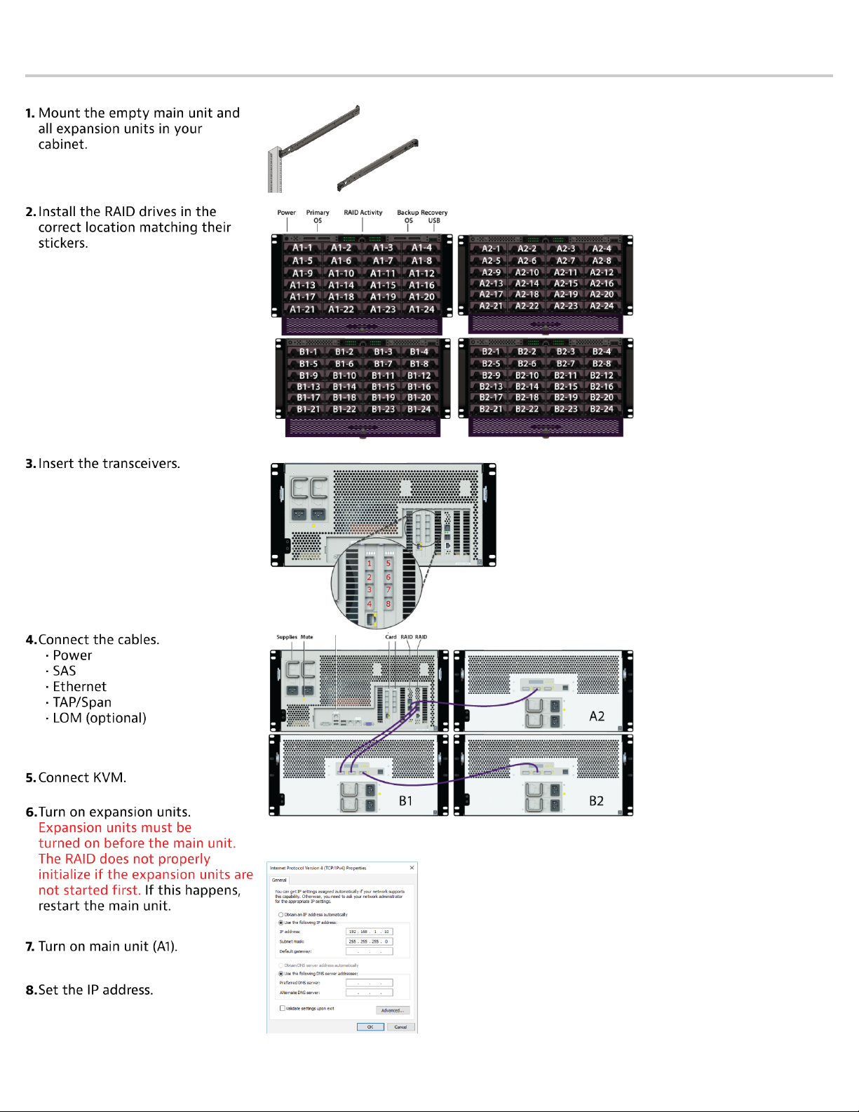
2. Attach the official rail kits to your server rack or cabinet.
3. Install the empty head unit (A1) into your server rack or
cabinet.
4. Install the empty JBOD unit(s) into your cabinet. Use a
server lift if necessary. Do not remove the RAID drives from
the chassis. Do not connect the power cables yet!
6. Using the SAS cables, connect the RAID ports from the
JBOD unit(s) to the head unit and to other JBOD unit(s).
See image on previous page.
Close inspection of the RAID ports on the JBOD unit(s) show
two ports labeled OUT and one port labeled IN. All ports are
bi-directional. Our recommendation is to use the left two
ports as IN and the rightmost port as OUT.
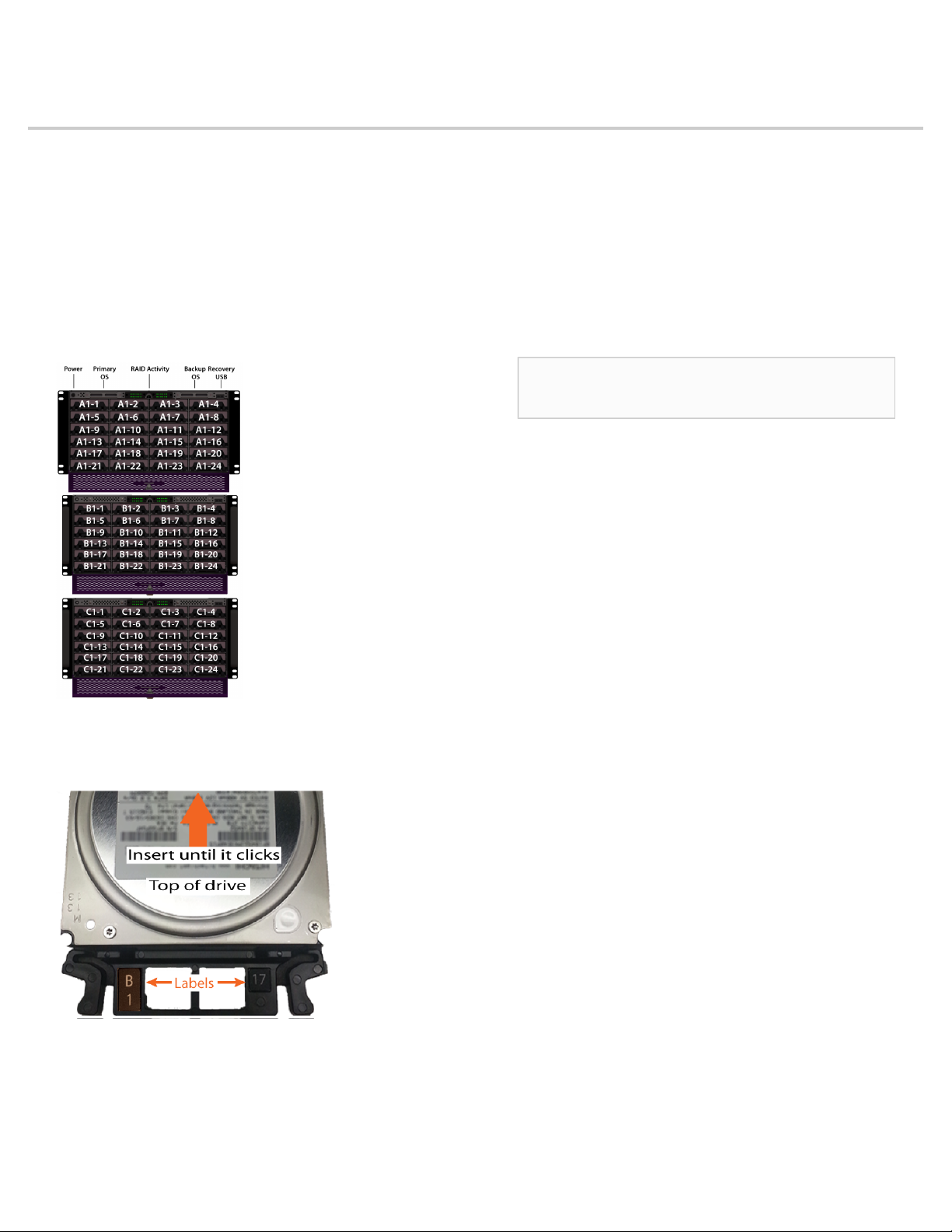
7. Install the RAID drives (page 5) into your appliance.
The RAID is pre-built at the factory for you and each drive
must be installed in a very specific location.
8. Connect all power cables for each JBOD unit. Do not turn on
yet!
9. Using an Ethernet cable, connect the 10/100/1000 port to
the network.
Connecting the 10/100/1000 port allows you to use
Windows Remote Desktop or other tools to control or
configure Windows or Windows applications, such as
Observer Analyzer.
10. (Optional) Connect an Ethernet cable from your router or
switch to the LOM or IPMI port.
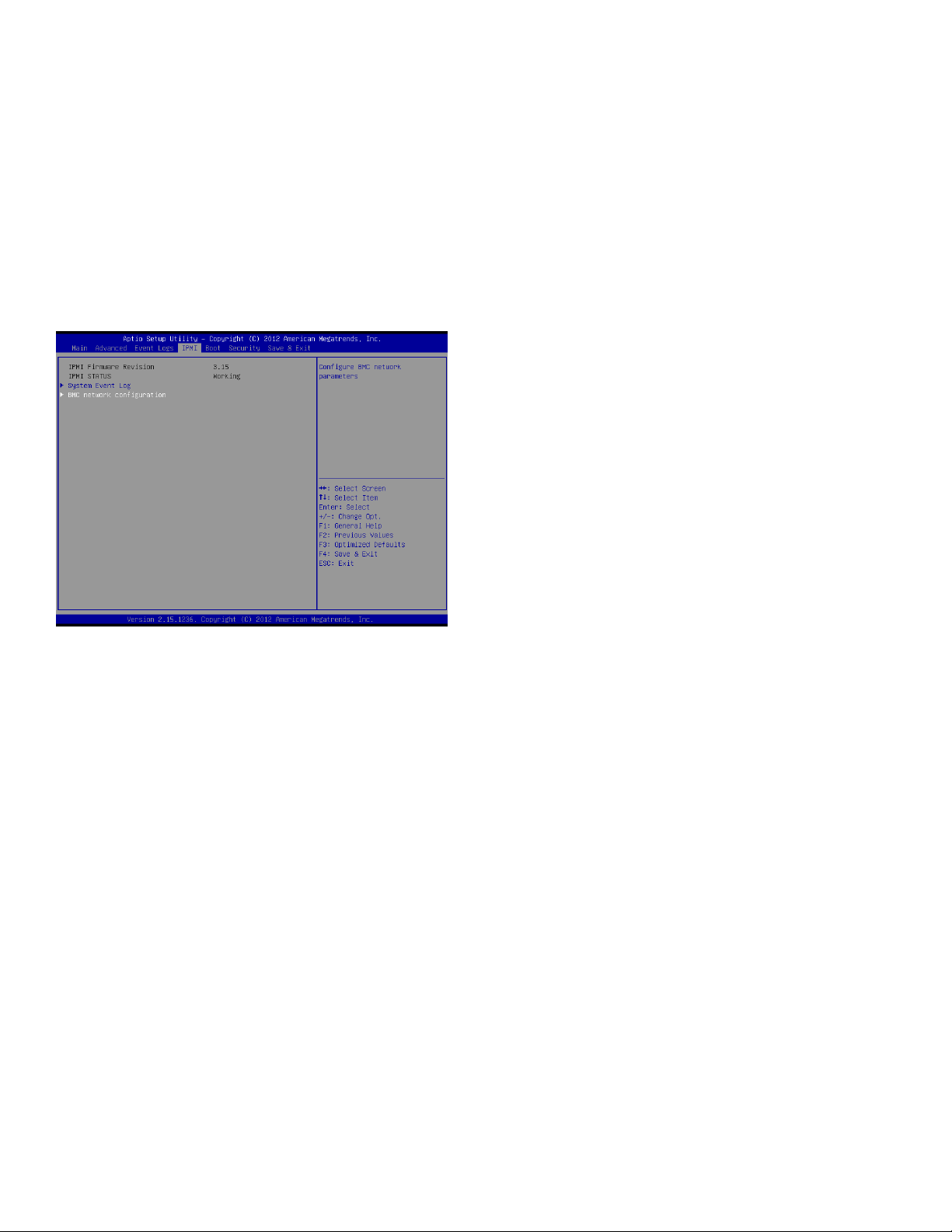
(Optional) A Lights Out Management or IPMI port
provides you a dedicated management channel for device
maintenance. It allows you to monitor, start, stop, and
manage your appliance remotely regardless of whether the
appliance is powered on.
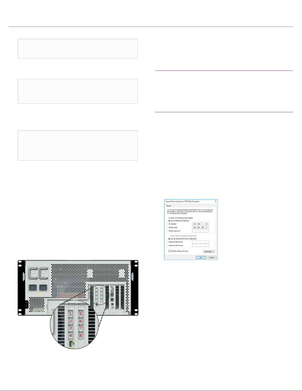
11. Install SFP transceivers (page 6)1 into the open slots on
the back of the capture card(s).
12. If you are connecting to SPAN/mirror ports of a network
switch: connect a straight-through Ethernet cable from the
SPAN/mirror ports on your switch to the SFP transceivers on
the capture card.
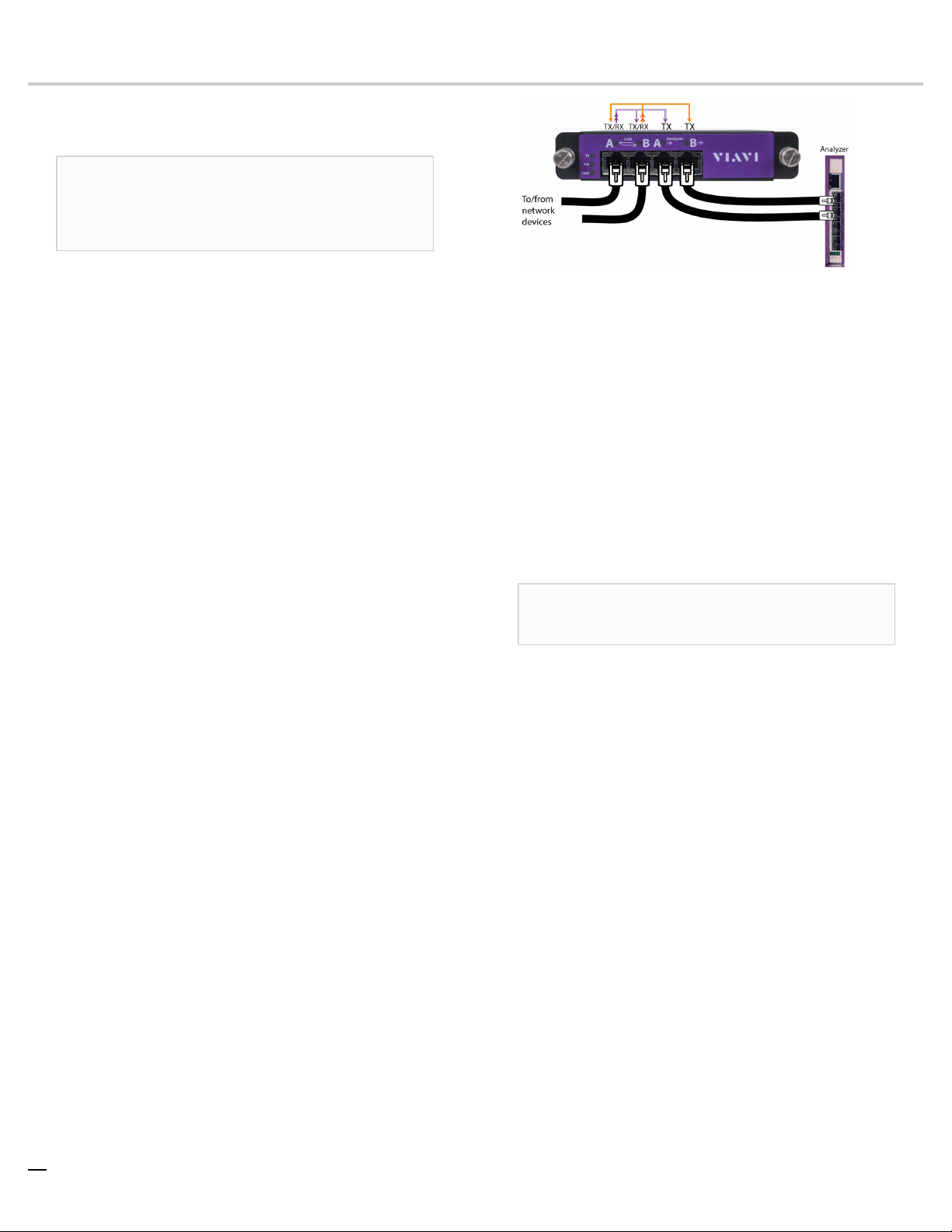
13. If you are connecting to a network TAP (sold separately):
a. Connect the TX port from your server, firewall, router,
or switch to the Link A port on the TAP.
b. Connect the TX port from your other switch to the Link
B port on the TAP.
c. Use two analyzer cables to connect the analyzer port
on the TAP to the SFP transceivers in the capture card.
d. If you have more than one TAP to connect, repeat the
process for each TAP.
14. Connect a monitor, keyboard, and mouse to the hardware
appliance.
You can use a KVM switch if desired. (The KVM must
be compatible with the operating system used on the
appliance.) The user input devices or KVM switch are
only temporarily needed to set the IP address, so you can
disconnect them after the IP address is set.
15. Turn on all JBOD unit(s).
Caution: The drive does not properly initialize if the
JBOD unit(s) are not started first. If this happens, restart
the head unit.
16. Turn on the head unit (A1) and wait for the RAID to initialize.
17. In Windows, change the IP address for the 10/100/1000
port (shown as OnBoard LAN 2 in Network Connections
in Windows) using information supplied to you by your
network administrator.
The default IP address (192.168.1.10) is printed on a
sticker attached to the top of the appliance.
18. Ensure the time zone settings match your environment.
19. (Optional) Change the LOM port in the BIOS using a static
IP address provided by your network administrator.
20. Double-click the Observer icon on the Desktop to start
Observer.
Next, give the 10/100/1000 IP address and LOM port address, if
using, to the Observer administrator. They need the addresses
to add this GigaStor probe to Observer to capture network
traffic with a probe instance.
Your hardware appliance is installed and on your network.
Next, give the ETH0 IP address and IPMI port address, if using,
to the Observer administrator. They need the addresses to add
this GigaStor probe to Observer to capture network traffic with
a probe instance.
1.SFP, SFP+, QSFP+, and QSFP28 transceivers are sold separately.

5 — Installing the drives in your Observer Platform appliance
Installing the drives in your
Observer Platform appliance
Failure to install the drives in the proper location will result in
poor read and write performance until the RAID array volume is
rebuilt.
Follow these instructions to install the drives correctly before
starting the appliance.
Stickers on each drive identify which slot it should be installed in.
The drive labeled 1 must be installed in the upper left slot of the
appliance.
1. Make sure that the appliance is turned off.
2. Locate the drives that comprise the array. The drives are
labeled to show you where they should be installed in the
drive cage. (Image may not exactly match your product.)
3. Gently insert each drive by squeezing the tabs and sliding
the drive into place until the tabs can engage the slots on
both sides of the drive. Do not use force!
Slightly lift the drive tabs to ease insertion.
4. Repeat until all of the drives are installed as labeled.
You should push each drive slightly to ensure that it is fully
seated. Additionally, you may want to visually inspect all of
the drives from the side to verify that they are all sitting at
the same approximate depth. Check any that are protruding
while the system is turned off.
5. Turn on the system, and check that every activity LED light
is lit. If not, turn off the system, reinsert the corresponding
drive into its cage, and confirm that it clicks into place.
How to handle hard drives properly
Be especially careful when handling and installing the hard
drives. Proper handling is paramount to the longevity of the
drive. The internal mechanism of the hard drive can be seriously
damaged if the hard drive is subjected to forces outside its
environmental specifications.
Caution: When transporting the hard drive, always use
an anti-static bag and the shock-absorbing packaging in
which the hard drive was delivered to you.
♦Always handle only one drive at a time.
♦Always have one hand under the tray to support the
weight of the drive when removing or inserting it.
♦Always hold the hard drive by grasping the long sides
that have mounting holes.
♦Always use an anti-static mat and wrist strap when
handling the hard drive.
♦Never stack hard drives on top of each other.
♦Never hit the hard drives in any way.
♦Never touch the components on the circuit board
assembly.
♦Never cover the small hole on top of the hard drive.
♦Never place the hard drive near equipment that
produces strong magnetic fields.
♦Avoid moving any hard drive that is turned on and
operating.
♦Avoid exposing the hard drive to extreme changes in
temperature to minimize the risk of condensation.
♦If the temperature difference between the storage
location and installation location exceeds 50°F/10°C, for
temperature acclimation purposes, leave the hard drive
in the new location overnight (or at least two hours)
before turning it on.

6 — © 2020 Viavi Solutions (21 Jan 2020)
Startup and shutdown (GS models)
Start: Turn on all JBOD unit(s) before turning on the head unit.
Caution: The drive does not properly initialize if the
JBOD unit(s) are not started first. If this happens, restart
the head unit.
Stop: Turn off the head unit using a clean operating system
shutdown before the JBOD unit(s). Always wait for the head
unit to power off before turning off the JBOD unit(s).
Caution: Shutting down a JBOD unit with the head
unit powered on leaves the RAID array in a confused
state. If this happens, 1) turn off the head unit, 2) turn
on JBOD unit(s), and 3) restart head unit.
How to install the SFPs
This product uses hot-swappable SFPs, but you should
disconnect any cables before changing the SFP modules.
Caution: Wear a grounding strap when handling SFPs
to avoid damaging them or other components. Avoid
exposure to laser radiation from optical components by
keeping the dust plugs installed until you are ready to
install the cables.
There are numbers etched into the back plate of each Gen3
capture card along the top (Figure 5). These etched numbers
represent the port number assignments from top to bottom.
For example, port 1 is at the top and port 4 at the bottom. This
helps you determine the port number that any SFP is plugged
into. If you need to connect the probe to a monitoring interface
(TAP or SPAN/mirror) different from that shipped with the unit,
simply obtain the necessary SFP for your application and insert
the desired interface.
♦The Gen3 capture card allows for mixing any 1 Gb and
10 Gb transceivers (SFP and SFP+ respectively).
♦Your transceivers can be inserted into any open port
and in any order.
♦You can hot-swap the connected transceivers at
any time, but it is recommended you then re-launch
Observer Analyzer so that the new speeds can be
identified.
How to set the IP address
Set the IP address of the hardware appliance while you still
have physical access to it, such as immediately after it is racked
and cabled. Setting the IP address ensures the hardware
appliance has a visible and permanent network presence.
Prerequisite(s):
♦A KVM switch or keyboard, monitor, and mouse are
connected. The user input devices or KVM switch are
only temporarily needed to set the IP address, so you
can disconnect them after the IP address is set.
♦The IP, subnet, and gateway or router addresses are
available and known to you.
1. Log in to the Windows operating system using the
Administrator account and its default password admin.
You can change the Administrator account password after
logging in. See the Windows documentation if necessary.
2. In Windows, choose Start > Control Panel > Network and
Sharing Center > Change adapter settings.
3. Right-click OnBoard LAN 2 and choose Properties.
OnBoard LAN 2 is the 10/100/1000 port on the right when
viewing the back of the system. OnBoard LAN 1 is the
Ethernet port on the left and is disabled by default.
4. Select Internet Protocol Version 4 (TCP/IPv4), and click
Properties.
5. Set the IP address, subnet mask, router or gateway, and
DNS server for your environment and click OK.
6. Click OK again to close the Properties dialog for that
network connection.
You interact with the hardware appliance through the Apex UI.
1. Navigate to https://hostname where hostname is the IP
address or DNS name for the appliance.
2. Log into the interface using the username admin and
default password admin.

7 — Configuring the LOM or IPMI port
Configuring the LOM or IPMI port
Your appliance comes with an on-board LOM or IPMI port that
provides you a dedicated management channel for device
maintenance. It allows you to monitor, start, stop, and manage
your appliance remotely regardless of whether the appliance is
powered on.
If you want to use Lights Out Management features, you
must first configure the IP address for the IPMI port from the
BIOS. Then, you should change the administrator password to
something different than the default.
1. Connect an Ethernet cable from your router or switch to the
IPMI or LOM port.
2. When starting your appliance, press Delete during POST to
enter the BIOS setup.
3. In the BIOS, choose IPMI > BMC network configuration.
4. Set Update IPMI LAN configuration to Yes.
5. Set Configuration Address source to Static.
6. Configure the Station IP address, Subnet mask, and
Router address.
These values must be valid and usable on your network!
7. Press F4 to save your changes and to exit the BIOS setup.
The system automatically shuts down and restarts.
Now you can log on to the IPMI web interface and change
the default password.
8. To change the default password, open a web browser to
http://<IpAddressOfIPMIport>, and log on with the user
name ADMIN and password ADMIN in caps.
IpAddressOfIPMIport is the station IP address you
configured in step 6. The user name and password boxes are
always case-sensitive.
9. Choose Configuration > Users, and select the second user
account (ADMIN account).
10. Click Modify User, and change the password.
You configured the IPMI port and changed the default
password.

8 — © 2020 Viavi Solutions (21 Jan 2020)
How to troubleshoot start-up issues
Very rarely a system may not start up or boot correctly. There
are a number of hardware or software reasons why that may
occur.
There are many steps that you can do to diagnose a system that
is not starting before contacting the company for assistance.
1. Does the appliance start?
●If no, see troubleshooting PSU about information
related to the power supply units.
●If yes, continue.
2. Does the appliance load the BIOS?
●If yes, continue.
●If no, contact Technical Support. You are done.
3. Does the Windows operating system start without errors?
●If yes, log into Windows using the user credentials for
the system. You are done.
●If no, continue.
4. Do you see any error messages in Windows?
●If yes, note the error message and contact Technical
Support. The issue may be related to the RAID card; skip
to step 10.
●If no, continue.
5. Are the RAID drives at fault?
See troubleshooting RAID drives.
a. Restart the appliance.
●If Windows loads, confirm you can log in. Continue.
●If Windows does not load, continue.
6. Are the RAID drives still at fault?
See troubleshooting RAID drives.
a. Turn off the appliance.
b. Disconnect every RAID drive by pulling out the drive
slightly—but not removing it entirely—from the
system.
c. Start the appliance.
●If Windows loads, confirm you can log in. Continue.
●If Windows does not load, continue.
7. Are the RAID drives still at fault?
a. Turn off the appliance.
b. Reseat every RAID drive.
c. Start the appliance.
●If Windows starts without error and you can log in,
then the issue was an anomaly with the RAID that was
resolved by reseating the drives. You are done.
●If Windows still shows an error, continue.
8. Is the operating system drive at fault?
See troubleshooting OS drives.
a. Turn off the appliance.
b. Remove the operating system drive and reinsert it.
c. Start the appliance.
●If Windows starts without error and you can log in, you
are done.
●If there are still errors, then it is likely that the
operating system drive is corrupted. Continue.
9. Is the operating system drive corrupted?
a. Follow the instructions in perform a factory reset.
●If Windows starts without error, the operating system
drive was slightly corrupted but the restore process
resolved the issue. You will need to install any Windows
and Observer Platform software updates. You are done.
●If there are still errors, the operating system drive is
faulty. Contact Technical Support for a replacement.
10. Is the RAID card at fault?
If you are seeing errors related to the RAID card during start
up an audible alarm will sound. Contact Technical Support.
Scan this code for more troubleshooting information.
Technical Support
Please contact technical support if your issues are not
represented or you need further help.
North America +1 800 526 7919
South America +1 800 526 7919
EMEA +44 1 959 569 880
APAC +44 1 959 569 880
All Other Regions viavisolutions.com/contacts
email nisupport@viavisolutions.com (North/
South America)
uknisupport@viavisolutions.com
(EMEA/APAC)
Support hours are 7:00 A.M. to 7:00 P.M. CST/CDT (for North
and South America) and 8:00 A.M. to 5:00 P.M GMT (EMEA and
APAC).
Table of contents
Popular Firewall manuals by other brands

Cisco
Cisco Small Business RV220W Administration guide

Lanner
Lanner HTCA-6600 user manual

Fortinet
Fortinet FortiGate FortiGate-100A install guide

NETGEAR
NETGEAR FVS318 - ProSafe VPN Firewall Router Reference manual

Fortinet
Fortinet FortiGate FortiGate-500A install guide

IBM
IBM Proventia Management SiteProtector SP2001 quick start guide

Cisco
Cisco 5510 - ASA SSL / IPsec VPN Edition Getting started guide

Cisco
Cisco Small Business RV215W quick start guide

McAfee
McAfee INTRUSHIELD 1400 datasheet

PaloAlto Networks
PaloAlto Networks PA-7000 Series Hardware reference guide

Hirschmann
Hirschmann EAGLE mGuard Series Description and operating instruction

HotBrick
HotBrick VPN 800/8 F user guide