Vicon V5.7-34.2AC User guide
INSTRUCTIONS FOR
1
NOTES
1
SH;;;i
KV.SEC.1
INSTALLATION AND OPERATION
V5.7-34.2AC MOTORIZED ZOOM LENS WITH AUTOIRIS
1. INTRODUCTION
The information in this instruction man-
ual covers the installation, operation, and
maintenance of the V5.7-34.2AC Motor-
ized Zoom Lens.
This unit must be installed y qualified
personnel using approved materials in
conformance with national, state, and lo-
cal electrical codes. Read these instruc-
tions completely before attempting to
install or operate this unit.
The V5.7-34.2AC lens features motor-
ized zoom and focus plus electronic cir-
cuitry for automatic iris control, as well
s a neutral-density spot filter. The lens
provides optimum viewing contrast re-
gardless of light conditions or brightness
variations within the scene.
This lens is powered with 8.516 VDC
power from the camera.
2. INSTALLATION
NOTE: The front element of a zoom
lens moves in and out as the lens focus is
changed. The closest focusing position
corresponds to the greatest extension of
the lens. When installing a lens in a
Do not exceed the maximum recommended housing, make sure that the lens is
jidy
distances between a lens and its control unit.
extended. Allow
l/4-inch
(0.6 cm) of
clear space between the extended lens
and the window.
Product specifications subject to change without notice.
Vicon part no. 8006-8759-00-00
VICON INDUSTRIES INC.
89 ARKAY DRIVE, HAUPPAUGE, NY 11788
TEL:
516-952-CCTV
(2288) TOLL FREE: l-800-645-91 16 FAX: 516-951
-CCTV
(2288)
VICON (U.K.) TEL:
44/
(0)
1489/566300
INFOFAX: i-800-287-1 207
CAUTION: Control units having the
Athree-position distance
switWch
MUST NOT be set for longer than
recommended distances or the lens
may be seriously damaged.
CAUTION: Do not mount an autoiris
Al
ens on a camera which is installed
on a autopanning unit. Such use
will cause excessive wear, as the
iris mechanism constantly compen-
sates for diflerent light levels.
2.1 Mounting the Lens
1. Screw the lens firmly into the
CS-
mount on the camera. Once the lens is
attached to the camera, the lens orien-
tation may be adjusted.
the square portion of the lens case is
to one side or the other.
3. If the lens is not oriented correctly,
rotate it in either direction against the
2. If the lens is too tall in its upright
position to be easily installed on a
mount or in a housing, rotate it so that
friction clutch in the lens mount to
obtain the best installation angle.
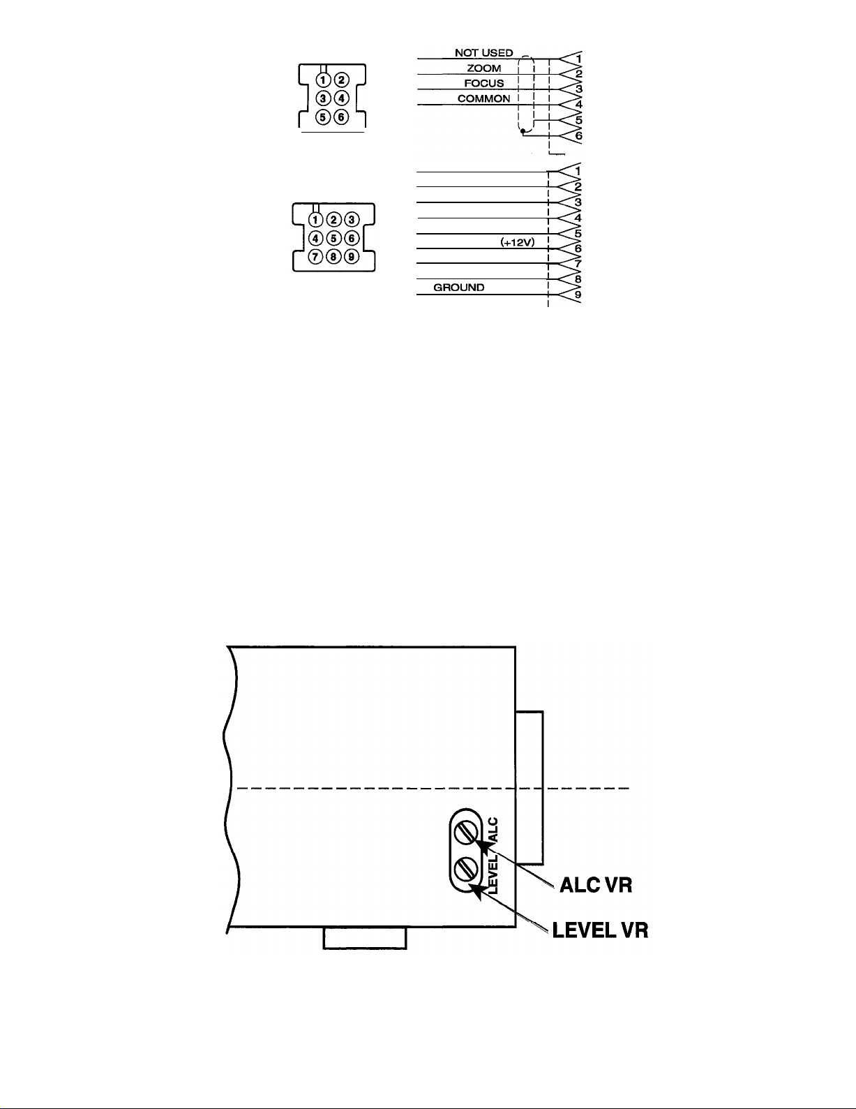
2.2 Wiring the Autoiris (AC) Lens
On AC lenses, the autoiris cable attaches
as the black (common) conductor. If the
directly to the camera and does not have
autoiris
cable has four conductors, the
a connector. The cable controlling the green conductor is not used and may be
autoiris
drive in AC lenses may consist cut off. Connect cables from the lens
of three or four conductors and a shield. control to the mating connector in the
For proper operation, the shield of this accessory pack according to Figure 1.
cable MUST be grounded to the same pin
Refer to the Circuit Diagram (Figure 3).
2.3 Focusing and Adjusting Procedure
The following procedure should be used
to obtain the best results in setting optical
and mechanical focus.
1.
Adjust the zoom function to the maxi-
mum telephoto setting, then focus on
a convenient distant object. Readjust
the zoom to the maximum wide angle
setting and check the focus. The focus
should remain reasonably sharp. If it
does not, the back focus (mechanical
focus) of the camera must be adjusted
according to steps 2 and 3.
2
X759-498

2.
Adjust the back focus by positioning 3. Zoom in to the maximum telephoto
the camera 25-50 feet (7.6-15 m) from position and focus the lens. Zoom out,
a flat vertical surface suitable for
fo-
watching the focus on the monitor. If
cusing. (A textured wall or a page of the image goes out of focus. Repeat
a newspaper are good focusing
tar-
the process until optimum focus is
gets.) Open the iris to its maximum. If obtained. Lock the back focus mecha-
the lens has au autoiris, reduce the
nism in place.
lighting to open the iris up to its maxi-
mum. This is necessary to obtain the
most accurate back focus adjustment.
2.4 Autoiris Adjustment
Autoiris
(AC) zoom lenses must be ad-
justed for optimum picture quality. Al-
though the automatic light control (ALC)
adjustment is provided on the lens, the
level control is preset at the factory and
should not be readjusted unless other
methods of optimizing the picture are
unsuccessful.
Before making any attempt to adjust the
lens, perform the following monitor
setup procedure: turn the BRIGHTNESS
and CONTRAST controls on the monitor
fully counterclockwise, then turn them
back to approximately midscale. These
controls vary from monitor to monitor,
but these settings are adequate for initial
adjustment.
2.4.1 Automatic Light Control (ALC)
This control adjusts the contrast level of
the picture. The limits of the adjustment
are labeled P (peak) and A (average), and
the control is set at average at the factory.
When making an adjustment, turn the
potentiometer a little at a time. If the
contrast is too strong, turn the potenti-
ometer clockwise, toward P; if the con-
trast is too weak, turn the potentiometer
counterclockwise, toward A.
2.4.2 Video Level (LEVEL)
The level control is preset at the factory
for optimum performance, so normally
no adjustment is required. Adjusting this
control when it is not necessary may spoil
the picture quality. If all other adjust-
ments fail to produce a satisfactory pic-
ture, adjust the LEVEL potentiometer.
The adjustment limits are low (L) and
high (H).
X759-498

Shipping Instructions
Jse the following procedure when
eturning a unit to the factory:
1. Call or write Vicon for a Return
Authorization (R.A.) at one of
the locations listed below. Re-
cord the name of the Vicon em-
ployee who issued the R.A.
VICON INDUSTRIES INC.
89 Arkay Drive
Hauppauge, NY 11788
5 16-952-CCTV (2288)
l-800-645-9116
2. Attach a sheet of paper to the
unit with the following informa-
tion:
a. Name and address of the
company returning the unit
b. Name of the Vicon employee
who issued the R.A.
c. R.A. number
d. Brief description of the
installation
For service or returns from
countries in Europe, contact
e. Complete description of the
problem and circumstances
under which it occurs
VICON INDUSTRIES (U.K.)
LTD
Brunel Way
Fareham,
PO 15 5TX
United Kingdom
44/(O)
1489/566300
Fax:
44/(O)
1489/566322
f. Unit’s original date of pur-
chase, if still under warranty
3. Pack the unit carefully. Use the
original shipping carton or its
equivalent for maximum
protec-
tion.
4. Mark the R.A. number on the
outside of the carton on the ship-
ping label.
4X759-498
AC LENS
VIEW
OF WIRING SIDE
LENS WITH PRESET
VIEW OF WIRING SIDE
NOT USED
ZOOM
FOCUS
LENS COMMON
ERROR RETURN
ERROR SUP (+12V)
ZOOM WIPER
FOCUS WIPER
GROUND (SHIELD)
Figure 1
Connector Diagram, AC Lenses
Figure 2
Lens Adjustment Location
X759-498

Preset Potentiometer
Supply (+) 1PURPLE
Focus Error
1
BLUE
Copyright
0
1998 Vicon Industries Inc. All rights
reserved.
1
RED
+9
VDC
Figure 3
Circuit Diagrams
Vicon and its logo are registered trademarks of
Vicon Industries Inc.
6
X759-498
Table of contents
Other Vicon Camera Lens manuals


Popular Camera Lens manuals by other brands


Sony
Sony VCL-ST30 operating instructions

Canon
Canon FD 35 - 70 mm instructions

Sony
Sony SAL-85F14Z - 85mm f1.4 Carl Zeiss Planar T Coated Telephoto... operating instructions

ARRI
ARRI Lenses brochure

Panasonic
Panasonic LUMIX G X Vario 45-175mm f/4.0-5.6 operating instructions

Nikon
Nikon AF-S VR 24-120 f/3.5-5.6G IF-ED instruction manual


