CONTENTS
Pages
FEATURES
AND
FUNCTIONS ......................................... .8
-
10
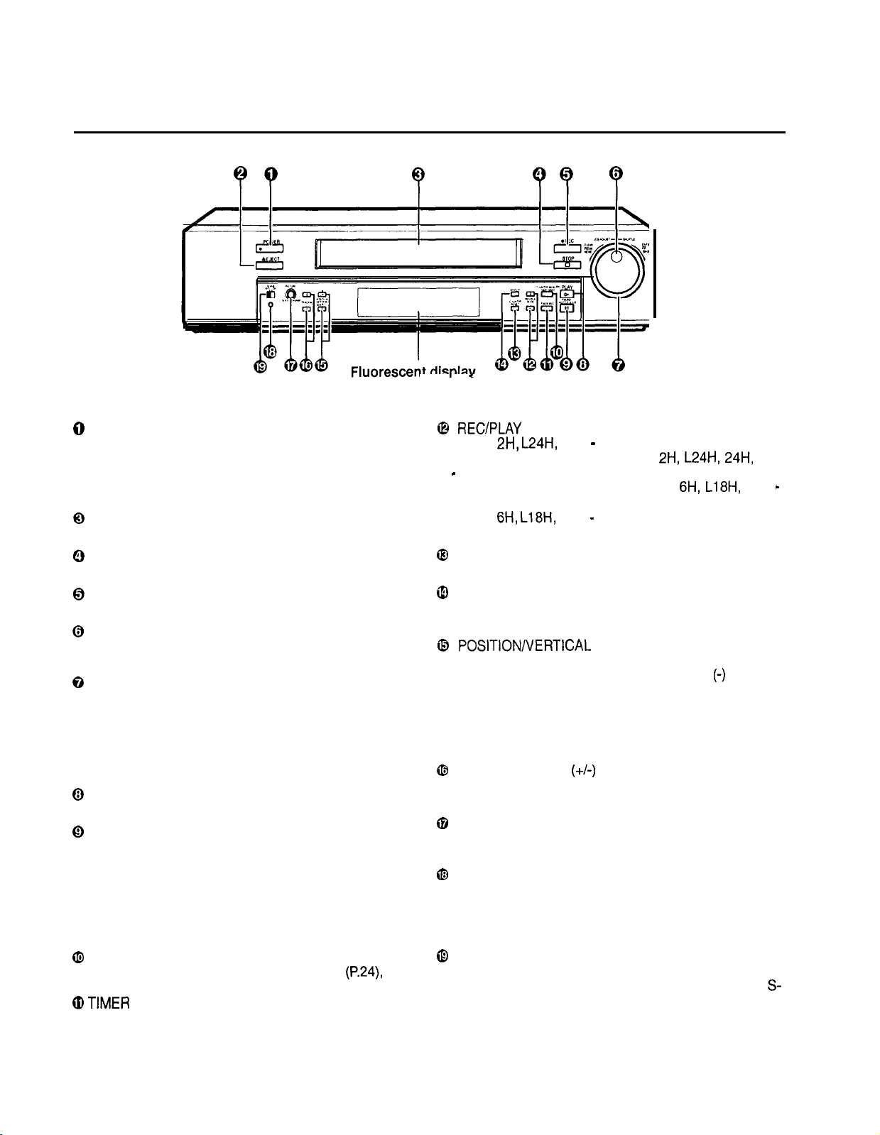
Front view
.............................................................................. .8
Fluorescent display
................................................................ .9
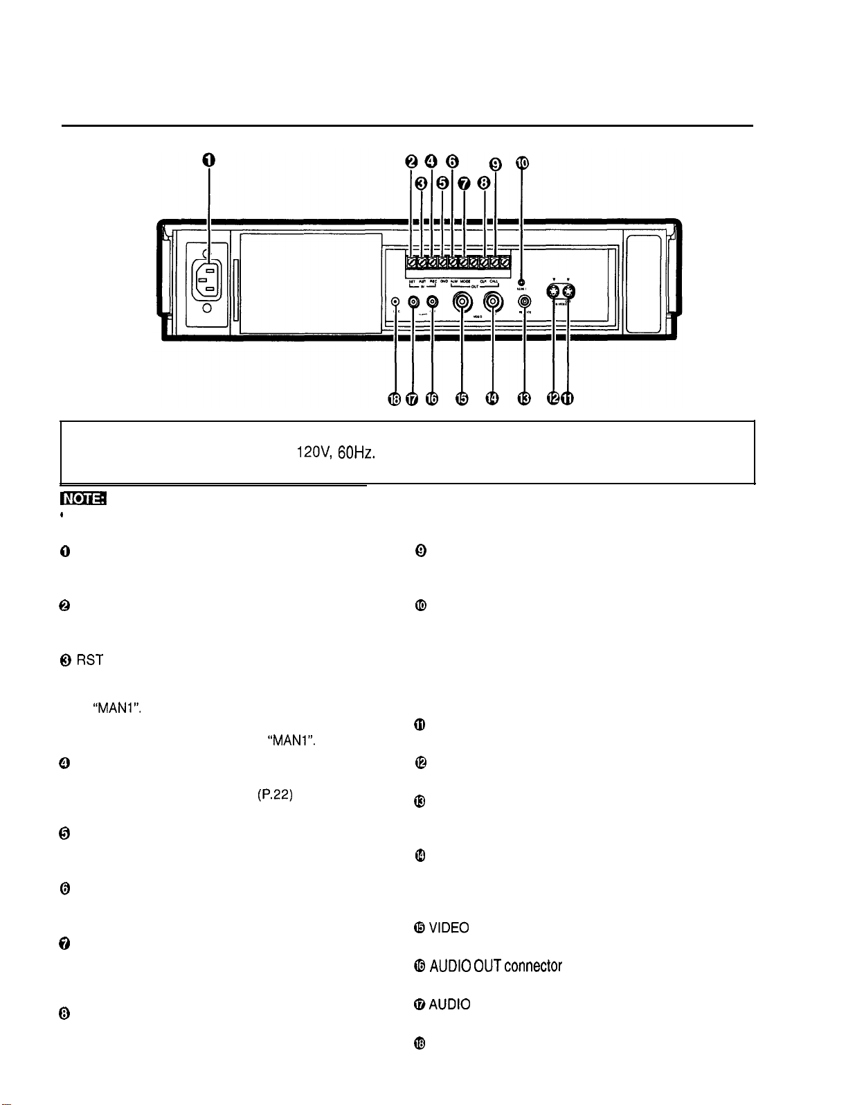
Rearview
..............................................................................
10
CONNECTING
WITH
OTHER
EQUIPMENT
...........................
11
SETTING
THE MENUS
.....................................................
12 -17
SETTING THE
PRESENT TIME
18
-
......................................
19
LOADING AND UNLOADING THE CASSETTE TAPE
..........
20
MANUAL RECORDING ....................................................
21 -23
Audio recording..
..................................................................
.21
Repeat recording
.................................................................
.22
Series recording
..................................................................
.22
Oneshot recording
..............................................................
.23
Synchronous recording
........................................................
.23
ADDITIONAL FEATURES .......................................................
24
Counter memory
..................................................................
.24
Tape counter
........................................................................
.24
Counter reset
.......................................................................
.24
Memory back-up in case of power failure
............................
.24
Recording after
a
power failure
............................................
.24
Power failure time display
.....................................................
24
Pages
Elapsed time display
............................................................
.24
TIMER
RECORDING .......................................................
.25
-
26
ALARM
RECORDING
.27
-
.....................................................
29
Alarm recording connection
.................................................
.27
External time clock adjustment
............................................
.27
Setting for alarm recording
..................................................
.28
Emergency recording..
.........................................................
.28
Alarm record time display
....................................................
.29
Locating the start of alarm recordings
.................................
.29
PLAYBACK
..............................................................................
30
Audio playback..
...................................................................
.30
SPECIAL EFFECTS PLAYBACK ............................................
31
ADJUSTMENT DURING PLAYBACK
....................................
.32
Tracking adjustment..
...........................................................
.32
Picture quality adjustment..
..................................................
.32
Vertical adjustment
..............................................................
.32
WARNING DISPLAY
................................................................
33
BEFORE CALLING FOR SERVICE ........................................
34
CONTROL INPUT/OUTPUT SIGNALS AND CIRCUITS.. 35
-
36
SPECIFICATIONS
...................................................................
37
FEATURES
Up to 960 hours of recording: an ideal video system for automated security and surveillance systems.
This time lapse VCR is designed especially for industrial, educational and security recording. In addition to ordinary 2-hour and 6-hour
recording modes, it has time lapse modes that permit recording of 18,24, 48, 72,96, 120, 168, 240, 360,480, 720 or 960 hours. The
recording mode can be extended up to 64,800 hours (for T-120 tape) if you choose one-shot recording with a 3 minute interval time.
Frame-by-frame playback and high-speed playback of longer recordings are also available. This adds up to a powerful surveillance
system for banks, buildings, traffic and parking lots, as well as a convenient scientific tool for observation of plant growth, animal
behavior and other time-intensive processes.
-
Audio Recording Record Check
When recording in 2H, 6H or L(linear)l8H. L24H mode, audio is
played back only during their respective modes.
S-VHS mode
This mode has higher resolution and picture quality than normal
VHS mode when using S-VHS tapes.
S-VHS ET mode
S-VHS ET recording using VHS tapes has closer picture quality to
the S-VHS recording (over 400 lines of resolution).
High Density Recording
-
H*D<EP>
High Density recording records 3x more fields than Normal Density
(SP). It reduces the time interval between pictures, providing more
pictures and smoother time lapse recording.
Tape Remaining Indicator
A bar indicator shows how much tape is left and/or that the tape
has approximately three minutes (in 2H mode) left.
Automatic Head Clog Detection and Cleaning
For continuous smooth operation, the VCR automatically detects
and cleans up foreign matter while recording, simultaneously
sensing the output from the video heads.
Easy Setting using a Monitor
The on-screen menus simplify setting-up procedures, These
menus can be selected even without the input of a video signal.
Easy Cueing with Alarm Recording
Index signals are added automatically al the beginning of “alarm
recording” for easy cueing. You can confirm the Alarm starting
time in the playback video on the monitor or with the Alarm list
using the Maintenance menu.
Time Date Search System
You can locate a specific Hour, Minute and Date to accurately find
an image on tape.
External Time Clock Adjustment
The on-screen time clock can be reset to the nearest hour by
applying a signal to the RST(RESET) IN terminal at the rear of the
VCR.
Correct recording can be confirmed by pressing the PLAY button
during recording.
Automatic Head Azimuth Selection
This VCR can automatically select playback heads for normal VHS
compatible Time Lapse recordings, or older Time Lapse recordings
made using two Same Azimuth video heads. Same Azimuth Time
Lapse recordings use VHS cassettes but cannot be played normally
by VHS compatible VCRs.
Full Lock Mode
Locking prevents the VCR from being operated by an unauthorized
third party.
Special Playback Features
These include still images, speed search, reverse playback, frama-
by-frame viewing in both directions, slow motion and high speed
viewing.
JOG DiallSHUlTLE Rlng
Use to search for the desired image. You can adjust the playback
speed with the SHUTTLE ring and search for an image frame by
frame with the JOG dial.
Recording Options
This versatile system offers a variety of recording options, including
daily and weekly timer recording, repeat and alarm recording.
Protection against Power Failures
Recording data including date, time and timer set-up, are stored
in backup memory, so the system can resume recording after a
power failure. The time of the failure is displayed on the monitor.
Digital <ELAPSED TIME> Display
The Elapsed Time of recording and playback is stored in a non-
volatile memory IC. The elapsed time display should be used as a
guide as to when periodic maintenance should be carried out.
Tape Use Counter
Displays how many times you have repeatedly recorded on a tape.
This is helpful for deciding when it is necessary to replace a tape.
Daylight Saving Time Setting
Daylight
saving time setting is available.
The clock can be put
forward
by one
hour by setting the menu.
7