R
Victaulic Company of America
Phone: 1-800-PICK-VIC (1-800-742-5842)
Fax: 610-250-8817
Victaulic Company of Canada
Phone: 416-675-5575
Fax: 416-675-5565
Victaulic America Latina
Phone: 610-559-3300
Fax: 610-559-3608
Victaulic Asia Pacific
Phone: 65-6235-3035
Fax: 65-6235-0535
Victaulic Europe
Phone: 32-9-381-1500
Fax: 32-9-380-4438
VICTAULIC®IS AN ISO 9001 CERTIFIED COMPANY
Style 441
Stainless Steel Vic-Flange
®
Adapter
2 - 6" (60,3 - 168,3 mm)
Installation Instructions
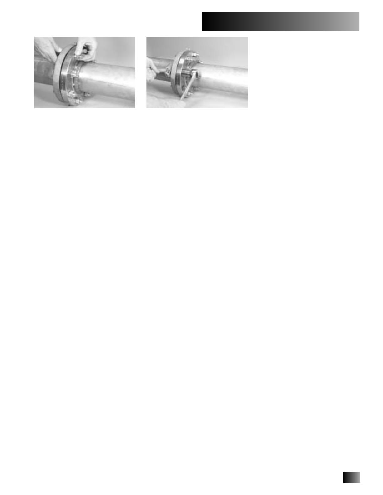
1.
The outside surface of the pipe (from
the pipe end to the groove) must be
smooth and free from indentations, pro-
jections, and roll marks to provide a
leak-tight seal for the gasket. All rust,
loose scale, oil, grease, and dirt must be
removed.
2.
The gray area of the mating face (Fig-
ure 1) must be free from gouges, undu-
lations, or deformities of any type for
proper sealing.
•Read and understand all installation instructions before attempting to install any
Victaulic piping products.
•Wear hardhat, safety glasses, and foot protection.
Failure to follow these instructions could result in serious personal injury, property
damage, and/or product damage.
•Depressurize and drain piping systems before attempting to install, remove, or
adjust any Victaulic piping products.
Failure to follow these instructions could result in serious personal injury and/or
property damage.
PIPE SIZE Sealing Surface
inches/
mm
Nominal
Diameter
in/
mm
Actual
Out. Dia.
in/
mm
“A” Max. “B” Max.
2 2.375 2.40 3.40
50 60,3 61 86
2
¹⁄₂
2.875 2.90 3.90
65 73,0 74 99
3 3.500 3.50 4.50
80 88,9 89 114
4 4.500 4.50 5.50
100 114,3 114 140
6 6.625 6.60 7.80
150 168,3 168 198
The following instructions are a guide for the proper installation of Victaulic Style 441 Stain-
less Steel Vic-Flange Adapters. Proper installation requires pipe that is prepared and grooved
in accordance with the latest Victaulic specifications.
•The Style 441 is designed for use with Class 150 raised-face flanges, in accordance with
ANSI B16.5. When a Style 441 is used with a flat-faced flange, the raised projections on
the outside edge and around the mating holes of the flange adapter must be ground flush
to the body. The shaded areas on the sketch to the left identify the projections that need
to be ground flush on both segments.
•The Style 441 cannot be used, unless it mounts flush to the mating flange; therefore,
flange washers, or anything else that prevents flush mounting, cannot be used.
• The Style 441 must not be used as anchor points for tie rods across non-restrained joints.
•The Style 441 must not be used against rubber coated surfaces or with wafer or lug-type
valves, or when the flange adapter does not mount flush with the mating flange.
•Because of the outside flange dimension, the Style 441 must not be used 90° to one
another on a standard fitting.
IMPORTANT
INFORMATION
PIPE AND MATING
FACE PREPARATION
ALWAYS VERIFY THAT THE GASKET IS SUITABLE FOR THE INTENDED SERVICE. Refer to publication 05.01 for complete information.
Figure 1
A
B
I-441
3307 Rev.B 8/02 © Copyright 2002, Victaulic ® Registered Trademark of Victaulic Printed in U.S.A Z000441000