20010790 / 07.01.2020 / 8 - 22
D. Installation
1. Installation
1.1 Check and follow all the points of paragraph C.2 “ATEX requirements” on page 6.
1.2 The pumps can be supplied in various ways:
⇒bare shaft pump: Select a coupling, coupling cover and ATEX standard motor adequate for the
performance of the pump, install them according to the instructions of the various
manufacturers.
⇒Pump on base prepared for a certain motor: Read in the attached technical sheet which motor
is going to be used. Install it according to the instructions of the coupling and of the motor itself.
⇒Bi-Block pump (code .BB.) without motor: Read in the attached technical sheet which motor is
going to be used. Install it according to paragraph H "Coupling for Bi-Block Pumps", page 20
and the motor instructions.
⇒Pump with motor: The pump is ready to be installed in a plant.
⇒Pump already assembled in a system: The installation was carried out by the installer. Please
follow the installer’s instructions. Please go to chapter D.2 “First start-up”, page 9
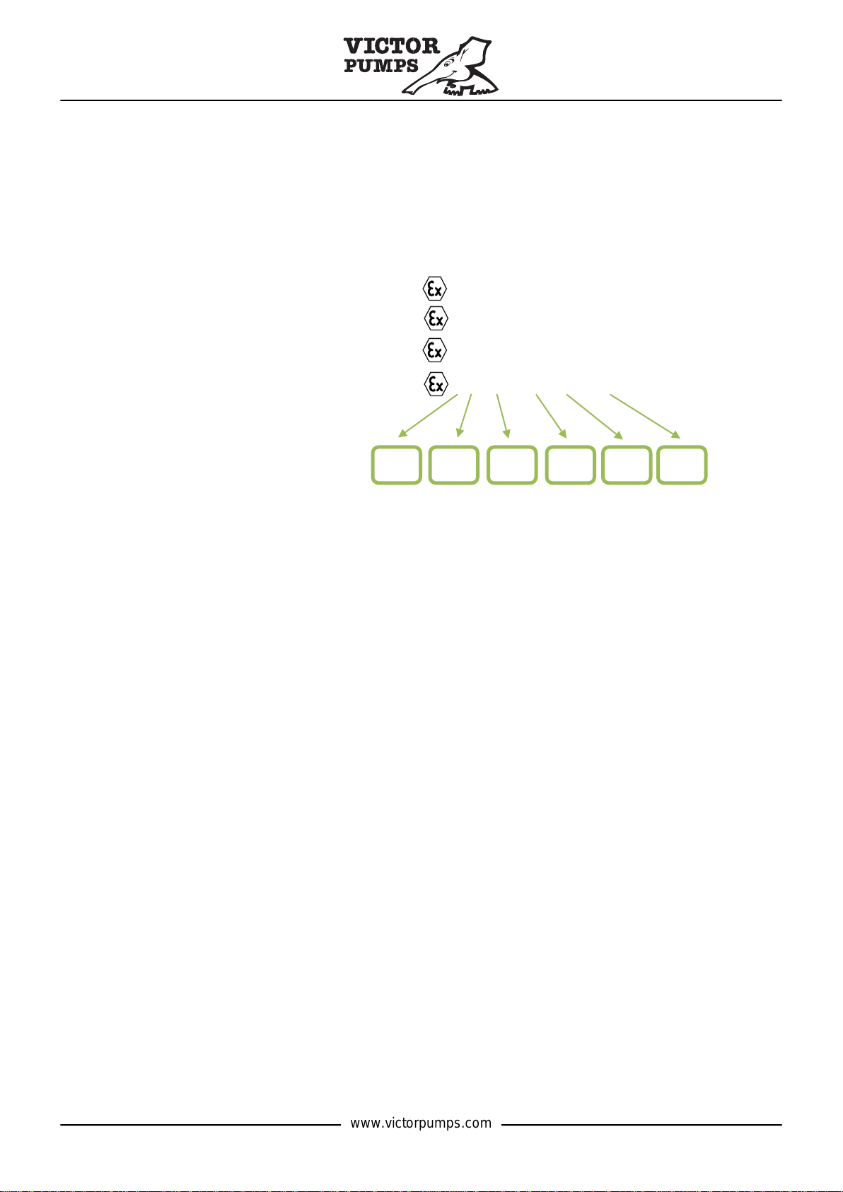
1.3 Please take into consideration the existing ATEX regulations as well as the local ones for installing
the pump in a system. The following ATEX certificates are required for a pump with motor:
⇒Pump
⇒Coupling (in Bi-Block pumps it is already included in the pump certificate).
⇒Motor
⇒Temperature sensor (if any).
The sum of these certificates must meet the system requirements.
1.4 The pumps are supplied with a protective liquid. The liquid is medicinal liquid (food) paraffin. In the
event that this liquid can contaminate the pumped product, wash the pump before installing it and
then fill it with the product to be pumped.
CAUTION The pumps should never be tested or washed with water because they might be damaged.
1.5 Place the pump on a level surface, as close as possible to the surface of the liquid to be pumped,
in an easy-to-reach position for maintenance.
1.6 The diameter of the suction pipe should be at least equal to that of the pump inlet and should be
as short as possible. Avoid unnecessary bends, elbows or bottlenecks. Liquid gases can be
pumped only in submerged pipes.
1.7 To easily install the pump, it may be useful to rotate the pump casing. Unscrew the screws of the
rear cover and rotate the pump casing. Refer to the paragraph D.2.5 on page 10 for the correct
position of the safety valve. To invert the position of the safety valve, unscrew the valve 4 screws
and screw them in again in the reverse position.
CAUTION Never rotate the casing of chocolate or magnetic pumps. This might damage the pump. If
necessary, contact your supplier for alternative suggestions.
1.8 We recommend the installation of a filter in the suction pipe/hose, near the mouth, in order to protect
the pump from the presence of foreign parts, welding residues, iron splinters, etc.
1.9 The size of the delivery pipe/hose must be appropriately calculated in order to reduce power losses
due to high friction. High pressures can reduce the life of the pump, especially if the liquid contains
abrasive substances.
1.10 Make sure that the weight of the pipes/hoses does not load on the pump casing. Check the
alignment of the flexible coupling.
1.11 If the pump is equipped with a non-return valve in the delivery line and is set at a pressure higher
than 2 bar, the pump cannot self-prime, since the air inside it cannot escape from the non-return
valve. In this case, fit the pump with an air-relief valve between the pump and the valve.
1.12 The safety valve (by-pass), available upon request, protects the pump casing and the pipes/hoses
in case the pump works with the delivery line closed or blocked. If the pump is used in both suction
directions, a double safety valve is available.