VICTOR TALKING MACHINE Victor Radio User manual

INSTR"UCTIONS
Victor
Radio
and
Victor Radio
with
Elect
roLa
auoa r[[ r8a, c. ] "r. m,
VICTOR TALKING MACHINE DIVISION
RADIO.VICTOR CORPORATIONOF AMERICA
CAMDEN, N. J., U.8. A.
'HISI'rAsTEil$vOtCE'
t

INSTR"UCTNONS
Victor
Radio
and,
Victor Radio
with
Elect
rola
IRAOE
MAR{SiEC. U. S. PAT.
OfF.
ti-iJ :
/,'/,;
o //; c'
/ ur-'r<-U-z
a/
.HIS MASJDR'SVOICE'
VICTOR TALKING MACHINE DIVISION
RADIO-VICTOR
CORPORATION
OF AMERICA
CAMDEN, N. J., U. S.A.

CONTENTS
P"gc
DESCRIPTION_____-_ ______3 .
INSTALLATION____- ________5
Equipment--- --------- 5
Removing
ShippingBlocks- -------------- 5
Installing
Radiotrons- ---------- 5
Installing
Selector
Larnp-------- ------------- --- 5
Connections
to Antenna
andGround-- ----------- 5
Connections
to Power
Supply---- -------- 5
Adjusting
Hum Controls ---------------- 6
Rearranging
Radiotrons-, --------------- 6
Harmonic
Modulator---- -------- 6
Mounting Turntable---- ------ 7
Regulating
Speed-- -------- 7
RADIO OPERATION-_- .---- 7
LOGGING STATIONS--- ----..---- 8
ELECTROLA OPERATTON _----------_----- 8
GENERAL INFORMATION---. ----,.9
Antenna- ---------- 9
Ground- -------10
Radiotrons___ -__--10 .
Careof Cabinet---- -----10
Careof Records------ -----ll
ElectricPickup- -----------ll
Lubricating
Motor- -------12
Failurein Operation-- -------------12
Service------------- ------.-----.12

DESCRIPTION
The mcst outstanding developments
in the fields
of radio
and record reproduction are offered in the new Victor Radio
and Victor Radio with Electrola.
Embodied in thesenew instruments are all the features
which are essential
to the listener's
completeenjoyment and
appreciation-quality musical reproduction, simplicity and
economy
of operation, and a high degree
of sensitivityand
selectivity.
The reproducing system comprisesthe radio unit, the
power-amplifier,
and the electro
dynamic reproducer. In the
combination Radio with Electrola the electricpickup is used
to translate
into electrical
energy
the mechanical
vibrations
of
the needle
in the recordgrooves. Unsurpassed
tone quality
and controllable
volume without distortion
for both radio and
recordreproductionareobtainedthrough the power-amplifier
and electro
dynamic reproducer.
All power for operationis obtained from the electric
light
line, and is controlled by a small snap switch on the radio
panel.
The tuning range of the instrument covers the entire
broadcast
band of 550to 1500
kilocycles
(545
to 200meters).

(- ( X -'7- l;)r.,,/ ,'/ .z ,l'1'
1tz
.1) Pr
IMPORTANT
The purpose of this book is to assist you in the
installation, operation, and care of the instrument.
The instructions should be read carefully before instal-
-f":;;,
*t!r ''
/ rs.
I '
*ltv14/\'
|Jx-2gv-,,.
IJX'z4W.ffn'"^*,L'
|Jx226ki;
);
power
plugv
*t7_,,
Electric
Pickup
Electro
Dvnamic
UX-226
Connections
' Reproduier ControlModulator
Fig. l-Back View of Instrument, Showin! Location of Radiotrons
in Radio and Power-Amplifier Units.
"Aa . \F
v' L ',.
I
I
Amplifier
Unit
/\rtrtL-l\tTE
'a
lag {or:it
l,;- lL
c ."J/-,r

INSTALLATION
l. Equipmeqt-All cquipment is supplied with the
exception
of the Radiotrons,tvhich are requlredasfollows:
6 Radiotrons
UX-226
1Radiotron
UY-227 2 Radiotrons
UX-245
I Radiotron
UX-280
. 2...Re.move
Shipping Blocks-Remove the various ship_
ping blo-cks
used
to supportthe radio,
the powerunit, and the
electro
dynamic reproducer.
--_-3,^lnstafling Radiotrons-Re{erring to Fig. l, insertthc
IJY-227 and the UX-226 Radiotronsinlheir io.k"t, in the
radiosetas shown. Insert the additional
Radiotrons
in the
power-amplifier
unit asshown
at the bottom of Fie. l.
4. Installing Selector Lamp-Remove theco,ier
overtlie
metalcompartment
in back
o{ the selector
scale.
T.his
cover
has.a
sprilg clip andcanbe removed
readily.place
the selec_
tor lamp in its socket,
a_ndreplace
thecovcr,
takingcare
that
it is fitted properly
sothat it will not rattle.
5. Connections to Antenna and Ground-Connect
the lead-in wire from thc antenna to the antenna bindirrg
post on the back of the radio set. Connectthe srouni
wire.
to the ground binding post. The successful
operaiionof
the ins.trument
islargelv
dependent
upona good
antenna
and
ground.
Seepages
9and
l0 for
adcscription
o.-f
the
best
anrenna
and ground
to beused.
6. Connections to Power Supply-Connect one end of
the powersupply cord ro the pou'er-implifierunit attachment
plug,(see
Fig. l) and the oiher end bf this cordto a lamo
socl<et
or'any other convenient
electrical
outlet of the prop"',
rating. Neaer
connect
the
powercord to a direct
currenr
i;rrLil.
2r^t^o
o! alternati^ng
current circuit of any ratingexcept
105to
120.volts,
50
to60cy'cles.*
If thereisiny doubtablout
thepower
rating,
consultyour locall-lectric
Light andPower
Company.
Turn the polver
switch,
shown;n Fig. 2, to the
right, and
note that all Radiotrons arelighted. The IJY-227 Ridiotron
will light brightly only near the top, while the other Radio-
trons will light with a dull glow. When certain
that all the
Radiotrons light propcrll', place
the metal cover,
furnished
in the_-gu^tirt
package
of the instruments with Elcctrola, over
the UY-227 Radiotron,forcing
the cover into the IJy-227
opening
in the metal
panel.
.lSpecial
instruments are availablefor operation on 105
to 120
volts, 25
to 40 cycles,
alternating current.

c0lilR0L ANI)
VtRllltRC0NTn0[svlllcH scA
Fig. 2-Radio Panel
7. Adjusting Hum Controls-With the power still
turned on, placethe transfer switch, shown in Fig. 2, in the
recordpositionto the right. With a small screw
driver,,
turn
the UX-226 hum control in the power-amplifier
unit, shown
in Fig. 1,slightly in either directionas
required
until the hum
of the instrument is a minimum. Turn the transferswitchto
the left to the radio position and alsoturn the radio volume
control to the left. With a small screw
driver, turn the UY-
227hum control in the radio set (see Fig 1) to the right or
left asrequireduntil the hum is a minimum.
Improved reception
and reduction
of hum may sometime,s
be effettedby reversing
the prongsof the power supply cord.
This can be done by removing the power plug, turning it
through a half circle,and reinserting
it.
Excessive
hum may sometimes
be causedby one gf the
Radiotrons not functioning properly,
particularly theUY-227.
A new Radiotron should
be tried i{ this conditionis noted.
8. Rearranging Radiotrons-Improved reception can
sometimes
be effectedby rearranging
the RadiotronsUX-226
iri their various sockets
in the radio set and listeningto the
reproductionuntil the best combination is found.
9. Harmonic Modulator-The harmonic modulator,
which controlsemphasis
on the basssection
of the scale,
can
be regulated to suit individual preference
or the acoustic
qualitiesof an unusual room. This control, shownin Fig. I'
is set in the factory for the best reproduction
over the entire
musical range, and should not ordinarily require further
6
lJ
I
N

adjustment. It can be regulated,
small screw driver, the bass being
advanced to the right.
however,
by turning with
increased
asthe control is
10.
MountingTurntable-In thecombination
Radiowith
Electrola move the electric pickup arm to the right as far
as possible.
Holding the turntable in both hands,
carefully
lower it over the turntable spindle. Make certain that the
slotin the turntableis
engagedu-ith
the pin in the spindle.
11. Regulating Speed-Regulate the speed
of the turn-
table to 78 revolutions per minute rvith the electric pickup
andneedle
on the record.
This can
bedonebv placing
i piece
of paper
under
theedgeof the recordon theturntabli, count-
ing the number of revolutions
for one minute, and turning
the speed
regulator
screw,
shownin Fig.3,rvith.a
smallscreri
driver until the proper
speedof 78 revolutionsper minute is
obtained. RADIO OPERATION
Referringto Fig. 2 for locationof the controls:
l. Snap
thepou'er
srvitch
to therightto the"on" position.
2. Turn the trans{crsn'itch to the left to the "Radio"
position.
3. Turn the radio volume control about half way to
the right.
4. After approximately30 seconds
from the time the
p.owej
s."vitch
is first turned on (this interval is required for
the Radiotronsto heatproperly),
move the station selector
lever
over
the scale,
lifting the leverslightly
rvhile
it isbeing
moved,
until a station
isheard.
5. If no station
isheard,
it may bethat nolocalor po\ver-
ful stationsare
broadcastinq,
in '"vhich
case
thevolume
iontrol
should
beadvanced
to the iighr to maximum,
and the station
selectorlever
again
moved
over
thescale
untila
stationis
heard.
It will benotcd
tl.ratthestation
selector
isreadily
oDerated
as
alever_,
and
that thefine
vernier
adjustment
iso6tained
by
turning.
the vernier
controlknob slightly to the right or left
as
requrred.
6. Adjust thc vernicr control for maximum volume by
turningthe knobto the right or le{t.
7. Regulate
to the desired
volume
by meansof the radio
volume
control.
8. Aftcr bccoming morc familiar rr'ith the simple and
rapid tuning operation,
it uill be possible
to slidethe station
selectorleverto any desired
kilocl'cleposition
of the dial to

tlectric Speed Motor
Record
PickupRegulator
StartingVolu-me
Switch
Control
Fig. 3-Electrola Playin$,
Compartment
receivea station which is known to be broadcasting and which
is n'ithin receiving range of the instrument.
9. When it is desired to discontinue operation, snap the
po\\rer switch to the left.
LOGGING STATIONS
The oositions on the sclector scale at which difrerent
stations are receivcd can be markcd on the light space pro-
vided if desired. The slot on the indicator is so shaped that
the scale
can be accurately marked w-ith a soft lead pencil to
ensure
ease
of crasure. It w'ill be noted that the scaleis cali-
brated directly in kilocy'cles,
so
that the lorv
{requency stations
(high u'ave length) will be rcceived tou'ard the left end and
ihJ ttigl'r frequency stations (lorv u.ave. lergth) toward the
risht end of the scale. A short line should be placed opposite
th1 scale
calibration at which the station is received,
and the
station call lettcrs then marked vertically as shown in Fig. 2.
ELECTROLA OPERATION
Rcferring to Figs.2 and3 for the locationof the controls
l. Turn the transfcr sw'itch
to the right to the t'record"
position.
2. Snap the power switch to the right to the "on" posi-
tion. 8

3. Insert a new Victor steelneedle
or a Victrola Tunss-
tone needle
in theelectricpickup, and
tightenthe needle
scrEw
firmly.
. .4. After placing the record on the turntable, swing the
pickup arm to the outer edge
of the record,
andpuil the iotor
starting switch forward.
5. After the turntable has acquired speed, lower the
electricpickup onto the record.
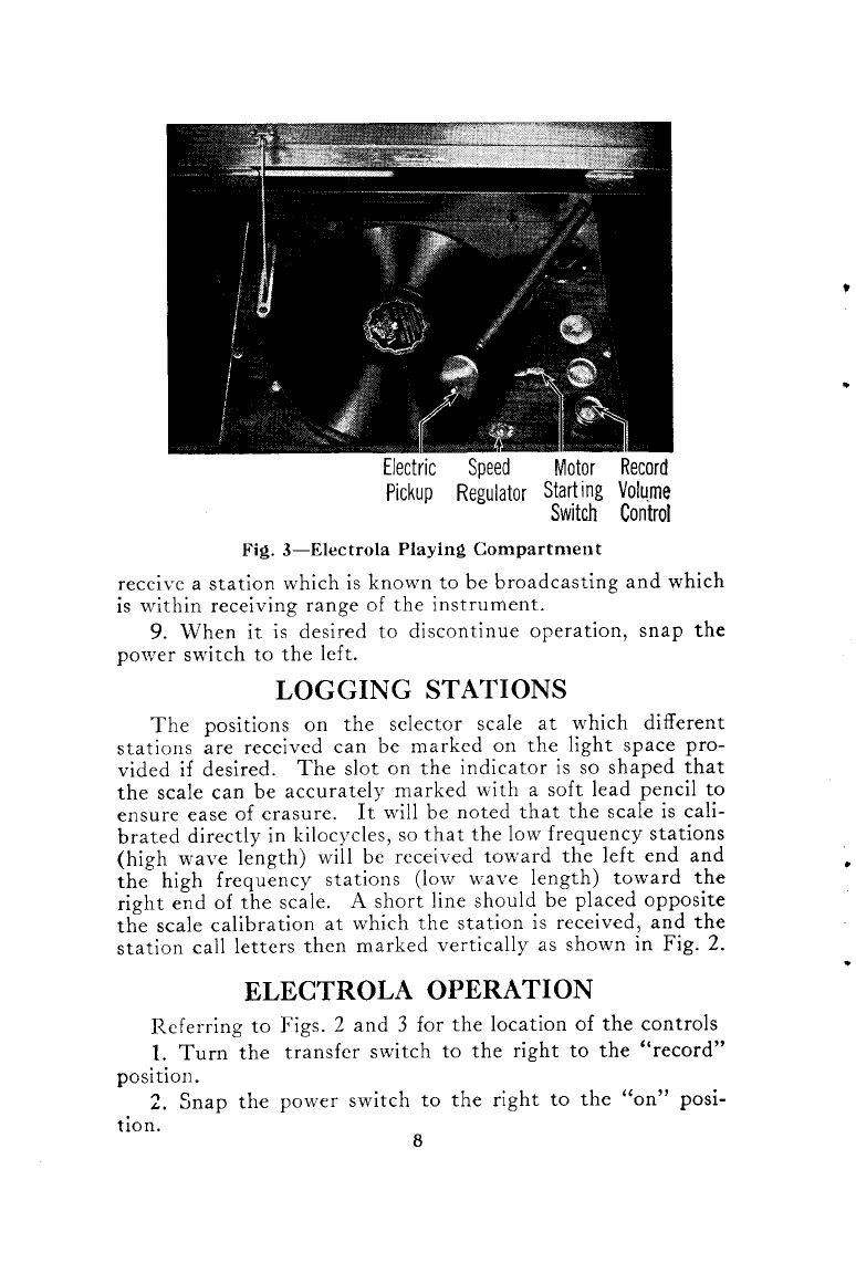
6. Regulate
the volume by means
of the
control. Maximum volume is obtained
when
turned all the way to the right.
record
volume
the control is
7. To discontinue operation of the Electrola. lift the
electricpickup and movi it to the right to cleartire record.
The motor will be
stopped
automaticaly at theendof a Victor
eccentricgroove record. (All Orthophonic recordshave this
eccentricgroove.) When playingrecords
without the eccentric
groove-,
stop the motor by pushingthe motor starting switch
toward the rear of the cabinet. Snap the power switch on
the radio panel
to the left to its "off" posiiion.
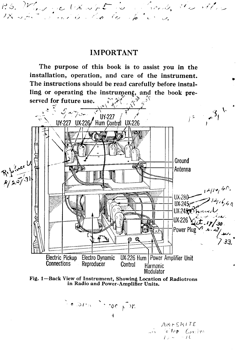
GENERAL INFORMATION
1. Antenna-fn seneral
the bestr€surts
will be obtained
by usinga single
wirJoutdoor antenna. It should
befrom 50
to 75,f.eetlong including the lead-inand ground wires,
which
shouldbe
short
anddirect. A lonEerantennawill increase
the
sens,itivity
and decrease
the selectivity,whiletheopposite
will
apply to a shorter
antenna. The antenna
shouldbe isolated
from other objects and as high as possible. It should be at
right angles
to electriclight, traction, power, and other wire
lines,
and shouldnot cross
either above
or belowsuchlines.
The antenna shouldbe supported
at both endsby glazed
porcelain or glass insulators. The lead-in wire should pre-
ferably be a continuation of the antenna wire. If ii is
necessary
to make a connection between the antenna and
lead-inwire, or between
sectionsof either,these
joints should
be securely soldered
together. The lead-in wiie should be
brought through the wall or window frame, and insulatedby
means
o{ a porcelain
tube. It is important that the antenna
and lead-in should not make contact with any object except
the insulators. When an outdoor antenna is used.it should
be protectedby means
of an approved
lightning arrester.

IWhere the installation of an outdoor antenna is not
practicable, satisfactory results may be obtained by..
using
lUo"i SOf""t of ordinary double iotton covered bell wire
(No. 18B. & S.)strung
around
the pict-uremolding. It,,may
alsobe run the length
of the attic. Such
an antenna
wlll not
be satisfactory
in a'building with metal lath under
the.
plaste
r'
An indoor antenna is not as efficientas a properly.lnstallecl
outdoor antenna. Variouspossiblearrangements
shouldbe
tried if the first is not satisfactory.
2. Ground-A good ground is as necessary
as.a good
antenna. The bestg"round-is
a good
electrical
connection
to a
water pipe. If thii is not con"venient,
a connectionto the
.t.rrn 'oi hot water heating
system
may be tried. Connec-
tionsto gas
pipes
should
.toi b" used. If none
of those
recom-
mended
""Uo""is available,
a pipeor metal rod may be driven
into the groundto a deptlrof 3 or 4 feet,
preferably
where
the
soilis m5ist. The groundconnection
should
be made
with a
g.ound clamp, the"wire being soldered
or held.by clamping
under a screw
or nut. Be sure
to scrape
and clean
tle PlPe
thoroughly before attaching
-
the ground clamp'. A Pgor
ground connectionmay not be ap-parent
on local receptlon
6ut it is an importani factor in diitant reception' Usuallv
connection to more than one ground, for instance to both
water and steam
pipes,
will improve reception.
3. Radiotrons-The only parts ordinarily requiring re-
placement
will bethe Radiotioni. These
shoild lastfor many
months if not abused
either by rough handling or by opera-
tion at too high voltage. The latter may-be
caused.by
oPerat-
ing the instniment wien the voltage
of'thepowerline exceeds
120volts.
Often improved reception
may beobtainedby interchang-
ing the Radiotrons
UX-226 as described
on page 6' -This
miv be the case
even
when the Radiotrons
are new' In no
."i!, ho*"*'er, should
any of thelJX-226 Radiotro-ns
be.placed
in tire IJX-2+3 or UX-280 sockets since the higher filament
voltage
would burn out theUX-226-
It is recommended
that one or two spareRadiotrons of
each type be kept on hand for emergencyuse.. 'I hls wlll
afiord i6me assui".rce
againstannoying interruptions due to
the possible
failure of i Radiotron, and will permit ready
deteition of any Radiotron not operating
properly.
4. Care of Cabinet-Victor cabinet cleaner is recom-
mended
for cleaning
and polishingthe cabinet. This Prepara-
l0

tion can be used freely u'ithout injuring the finish o{ the
cabinet. The cleaner
can be ourchasedfrom anv Dealer in
Victor products.
5. Care of Records-Records should be kept as free
from dust as possible. Gritty dust on the record not only
wears
out the recordrapidly, but causes
harshand unpleasant
reproduction. The recordsshould not be exposedto severe
heat, and should be cleaned
only by brushing with e velvet
or plush pad. If a recordbecomes
crackedor badly scratched,
it is best to destroy it. Playing a scratched or imperfect
record
may resultin injury to the electric
pickup.
6. Electric Pickup-Imperfect Reproduction-A loose
needle
may causenoisy reproduction. Hence, if your Elec-
trola reproduces
improperly, seethat the needle
is securely
fastened
in the electricpickup.
If you are using steelneedles,
put in a new needleafter
every record. The Tungs-tone needle
can be used until the
reproduction becomes
imperfect. The Victor full-tone steel
needle
or full-tone Tungs-tone
needles
give the bestreproduc-
tion, and only Victor needlesarerecommended.
If noisy reproduction should develop and tightening or
changingthe needlesdoesnot eliminate the condition which
persists
with various records,it is possible
that the electric
pickup is injured or out of adjustment. Take the pickup
to a dealer in Victor products for repairs.
*nf9liliiiilbilin,
OIL
UPPER
ANN
l-owEn luFtilr^a, c
sprlot! eari-Ni-.
MOTOR
CORD
FiS. 4-Electric Motor Oiling Diagram
0[.FRtcltoN
I-EATiIER
ll

7. Lubricating Motor-The Electrola motor should be
kept clean and should be lubricated at least once in six
months. To oermit readv inspectionand lubrication of the
motor, ."-ovi the turntable and the four screwsat the cor-
nersof the Electrola motor board. Lift up the front edgeo{
the motor board. The parts requiring lubrication are shown
in the oiling diagram, Fig. 4. Before lubricating, wipe the
motor with a clean cloth dampened with kerosene. The
properlubricants requiredfor the motor can be secured
from
any dealer in Victor products, and only Victor lubricants
are recommended. Samples of the proper lubricants are
furnishedwith the instrument.
8. Failure in Operation-Should the instrument at any
time become inooerative. or its oDeration become unsatis-
factory, determine first that it is b^eingsuppliedwith power
by observingif the operating lamp in the rear of the tuning
scale
is lighted when the power switch is on. Then observe
if
all the Radiotrons in the radio set and the power-amplifier
arelighted.
Even thoughall the Radiotrons seemto light, the
trouble may be due to the improper functioning of one of
theseunits or to a poor contact in one of the sockets. Dis-
connect the power supply cable from the instrument by
pulling the powerplug. Removeall the Radiotronsfrom their
sockets,
one at a time, and clean
the contact pins with sand-
paper. Wipe the pins care{ully; then slidethe Radiotron in
and out of its socket several
times. If the operation is not
yet corrected, replaceeach Radiotron, successively,
with a
new oneof the propertype until the poor oneis detected.
If the instrument still operatesimproperly, examine the
connections
of the antennaand sround. Theseshould all be
goodmetallic connectionsfreefrom any corrosion.
9. Service-The tests described above can be readily
carried out, but you should look to your Victor dealer for
assistancein caseof trouble. Ordinarily, arrangements
canbe
made with the dealerfor a periodicalinspectionand test of
the instrument at a reasonable
price. He iscapable
of render-
ing efficient service,and it is recommended
that you take
advantase
of this service.
L2 Part5273Q

Other manuals for Victor Radio
1
This manual suits for next models
1
Table of contents