Simrad RD68 User manual

SIMRAD
A KONGSBERG Company
SIMRAD Fixed VHF
DSC Radio
RD68
Service
Manual

SIMRAD
A KONGSBERG Company
SIMRAD Fixed VHF
DSC Radio
RD68
Contents

1
CONTENTS
1 INTRODUCTION
1.1 Electronic PCBs
1.2 Mechanical Components
2 OPERATION
3 ASSEMBLY INSTRUCTIONS
3.1 RD68 Pre-Assembly
3.2 RD68 Final Assembly
3.3 Fist Mic Assembly
3.4 Telephone Handset Assembly
4 MECHANICAL ASSEMBLY DRAWINGS
4.1 Assembly PCBs Matched Pair
4.2 Assembly Front Panel
4.3 Assembly Fist Mic
4.4 Assembly Telephone Handset
5 CIRCUIT DESCRIPTIONS
5.1 Receiver / Transmitter PCB Assembly
5.2 Control PCB Assembly
5.3 Second Receiver PCB Assembly
6 CIRCUIT DIAGRAMS
6.1 Circuit Schematics
6.2 Component Lists and Layouts
7 PROGRAMMING AND CONFIGURATION
7.1 Channel Characteristic Programming
7.2 Using the Programming Software
7.3 Altering NVM Data
8 FAULT FINDING
8.1 Common User Faults
8.2 Common Technical Faults
9 SPARE PARTS DETAIL
9.1 Spares List
9.2 Service Aids

2
10 TECHNICAL NOTES

SIMRAD
A KONGSBERG Company
SIMRAD Fixed VHF
DSC Radio
RD68
Introduction

3
1 INTRODUCTION TO THE SIMRAD RD68 FIXED DSC VHF RADIO
The Simrad RD68 is a combined VHF radio, watch-keeping receiver and Class
D Digital Selective Calling (DSC) unit to facilitate routine and distress calling on
VHF Channel 70. Digitally Selected Calls are quicker and simpler to make than
traditional voice calls using Channel 16 and should a distress situation occur, an
alert can quickly be raised indicating identity, position and nature of the
emergency and automatically establish communication on the emergency voice
channel. The RD68 is robustly constructed using a pressure die cast aluminium
case for effective heat dissipation ensuring maximum transmission performance
even after many hours of constant use.
The RD68 has full international channel capability; 16 pre-programmed private
channels; features Dual Watch, Tri Watch, Scan and full memory operation;
back-lit LCD display and is available with either fist-mic or telephone handset.
The main components of the Simrad RD68 are:
1.1 Electronics PCBs
a. Receiver / Transmitter PCB Drawing No. E03866
b. Control PCB Drawing No. E03656
c. Second Receiver PCB Drawing No. E03211
d. Fist Mic Drawing No. E03283
e. Telephone Handset Drawing No. E03308
1.2 Mechanical Components
a. RD68 Chassis Drawing No. E03848
b. RD68 Assembly Drawing No. E03847
c. Fist Mic Assembly Drawing No. E03161
d. Telephone Handset Assembly Drawing No. E03162

SIMRAD
A KONGSBERG Company
SIMRAD Fixed VHF
DSC Radio
RD68
Operation

4
2 OPERATING THE SIMRAD DSC VHF RADIO
This Service Manual only contains operating instructions for those features of
the Simrad RD68 Radio that are not normally available to the end user. For
details of normal operation please refer to the Simrad RD68 Instruction Manual,
E03912.
LCD Test Mode. The LCD test mode may be entered by holding Soft Keys 2
and 4 on power up. Depressing each key in turn will then fill the display with the
appropriate characters. The radio must be turned off to exit test mode.

SIMRAD
A KONGSBERG Company
SIMRAD Fixed VHF
DSC Radio
RD68
Assembly
Instructions

5
3 ASSEMBLY INSTRUCTIONS
3.1 RD68 Chassis Pre-Assembly
The main transmitter and receiver and second receiver PCBs are a
matched pair and replacement of either requires the tuning of both to be
checked and adjusted as necessary. Position the PCB over the Chassis.
Apply a small amount of Hellerman sleeving oil to the part of the Red and
Black power and the red and blue NMEA leads inside the chassis, to
provide lubrication and facilitate withdrawal from the chassis as the board
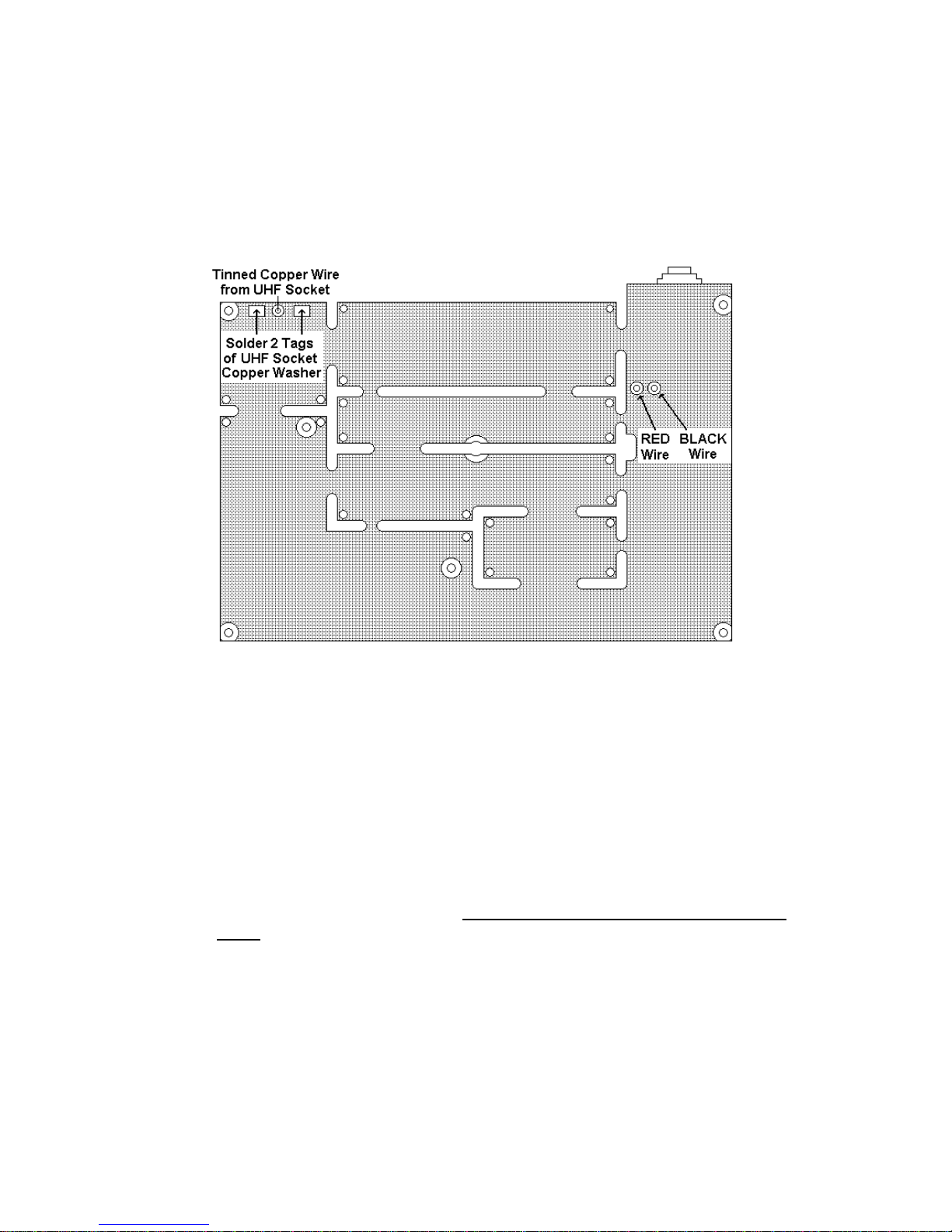
is set down. Ensure that the 2 copper tags from the washer on the
Antenna socket are standing up clear and insert the tinned copper wire
from the rear of the Antenna socket up through the plated hole in the
board. Fit the PCB into the chassis, carefully pulling the 4 leads through
the grommet to remove excess from the chassis interior. Locate the PCB
over the ribs in the chassis and push down to position the PCB flat into
the casting. When the board is correctly fitted, refer to drawing No
E03848 and fit 2 - M3 X 10 screws 200048 into the front of the chassis to
secure the heatsink in place, do not fully tighten these screws at this
stage .
Fit 1 washer 200081 onto each of the 2 screws M3 x 16mm 200200, and
fit into the 2 holes at the back of the chassis. When all 4 screws are in
place, lightly press down on the front part of the PCB until the front panel
connectors are clearly visible and permit engagement of the front panel
without interference. (See drawing below)

6
When this has been achieved fully tighten the rear module screws and
then the heatsink screws at the front.
Solder the tinned copper wire from the Antenna socket into the board,
then fold down the 2 tags, from the Antenna socket copper washer, onto
the PCB and solder both tags down to the pads.
3.2 RD68 Final Assembly
Fit the Cover Seal E03117 into the top cover ensuring that the seal lays
into the recess around the cover. Refer to drawing E03847, place
Screen / Insulator Assembly E03223 on top of the PCB in the Chassis
Assembly E03848 with the Leatheriod insulator down towards the board.
Fit Top Cover onto Chassis assembly and fix down using 5 off M3 x 16
Pan Head Slot Screws fitted with M3 Nyltite Sealing Washers 200252,
fully tighten ensuring that the seal remains correctly fitted. Refer to
drawing E03849 and fit the Front Panel Seal E03116 to the Front Panel
Assembly E03850 as shown, ensuring that the 6 small 'feet' attached to
the seal sit down onto the PCB. Take the four sets of wires from PLUGS
1 –4 on the front panel and, referring to the drawing below, plug them
into their correct connectors as shown.

7
Offer up the front panel to the chassis and, ensuring that the seal is still
correctly located, fit the front panel. Refer to drawing No.E03847 and
onto each of the four No.6 x 1/2" Pan Head Screws 200005, fit a M3.5
Nyltite Washer 200253. From the rear, fit these screws through the
chassis and into the front panel. Screw on the front panel, fully
tightening the screws.
3.3 Fist Mic Assembly
Refer to Drawing No. E03161 and fit the PTT Grommet E03143 into the
web in the front case ensuring that it is correctly seated. From the end of
the Cable Assembly E03175 strip and remove the outer insulation for
15mm. Cut off the Blue ,Green, Orange and Black wires, (not used),
flush with the end of the outer insulation. Strip 5mm of insulation from
the ends of the Red and White wires, twist and sleeve the screen and tin
the ends. Pass the end of the cable up through the bottom hole in the
front case, apply a small quantity of Hellerman Sleeving Oil to the cable
and slide on Cable Grommet E03141. Pull the cable and grommet
through together, until the grommet is fully home, ensuring that the flat on
the head of the grommet lays against the inside of the case, then pull
cable back through grommet by approximately 100mm. Wipe off any
excess sleeving oil from the cable. Solder the cable connections to the
PCB and position the PCB assembly onto the 2 mounting pillars. Route
the cable into the case, pulling out any excess wire, until the PCB and
cable lay neatly into the case. Ensure the PTT Key hits the push switch
before fixing the PCB assemble into the case using 2 screws (200036).
Into the groove around the outside of the Rear Case E03133 fit a Case
Seal E03136 ensuring it is pushed fully home. Fit the PTT Key E03134
so that the spring leg in the centre of the key with a guide either side,
faces out, and the peg on the other side of the key faces into the case
front. Fit the rear case onto the front using washer (200257) and screw
(200023) and tighten firmly.
3.4 Telephone Handset Assembly
Refer to Drawing No. E03162 and fit the PTT Grommet E03143 into the
side wall of the front case ensuring that it is correctly seated. From the
end of the Cable Assembly E03175 strip and remove the outer insulation

8
for 35mm. Cut off the Blue wire flush with the outer insulation, (not
used). Cut back the Red wire to 20 mm long from the end of the outer
insulation, the Orange and Black wire to 30 mm and the Green and White
wire to 35 mm. Strip and tin the ends. Pass the end of the cable up
through the hole in the bottom of the front case, apply a small quantity of
Hellerman Sleeving Oil to the cable and slide on Cable Grommet
E03141. Pull the cable and grommet through together, until the grommet
is fully home into the case, ensuring that the flat on the head of the
grommet is facing out, not towards the wall of the case. Then pull cable
back through grommet by approximately 30mm. Wipe off any excess
sleeving oil from the cable. Secure with Cable Tie 200026. Fit the
handset weight E03311 and hold in place by fitting 3 Grommets 190024
onto the pillars. Solder the five wires and screen from the coiled cable
and the two wires from the speaker to the PCB E03309. Position the
PCB into the case on top of the three pillars retaining the weight and
using 3 Screws 200082, fix the PCB into the case. Fully tighten the 3
screws. Fit PTT Key and check that the key operates the switch. Into
the groove around the outside of the Rear Case E03140 fit Case Seal
E03142 ensuring it is pushed fully home. Fit the rear case onto the front,
ensuring the seal remains in place, using 6 Screws 200055 with washers
and tighten screws firmly to secure front and rear case halves together.

SIMRAD
A KONGSBERG Company
SIMRAD Fixed VHF
DSC Radio
RD68
Mechanical
Assembly
Drawings

9
4 MECHANICAL ASSEMBLY DRAWINGS
4.1 Assembly Chassis E03848
4.2 Assembly PCBs & Power Module E03867
4.3 Assembly Mobile Radio E03847
4.4 Assembly Front Panel E03849
4.5 Assembly Fist Mic E03557
4.6 Assembly Telephone Handset E03558


Other manuals for RD68
3
Table of contents
Other Simrad Radio manuals

Simrad
Simrad HT50 User manual

Simrad
Simrad RS20S User manual

Simrad
Simrad RS40 User manual

Simrad
Simrad RS25-E User manual

Simrad
Simrad RS90S User manual

Simrad
Simrad HT50 User manual

Simrad
Simrad RD68 User manual

Simrad
Simrad RD68 User manual

Simrad
Simrad RD68 User manual

Simrad
Simrad WR20 RemoteCommander User manual

Simrad
Simrad SHIPMATE RS8100 User manual

Simrad
Simrad RS35 VHF HS35 User manual

Simrad
Simrad RT62 User manual

Simrad
Simrad Axis 200 User manual

Simrad
Simrad HH36 User manual

Simrad
Simrad RS25/AHK05 User manual

Simrad
Simrad RS86 User manual

Simrad
Simrad RS90 User manual

Simrad
Simrad RS10U User manual

Simrad
Simrad Axis30 User manual