Silvus StreamCaster MIMO User manual

Document Number
10017C000
Version
3.9
Date
3/17/2015
Silvus Technologies, Inc.
10990 Wilshire Blvd, #1500
Los Angeles, CA 90024
StreamCaster MIMO Radio
User Manual

StreamCaster MIMO Radio User Manual 3/17/15
10017C000 Silvus Technologies Confidential Page i
Notice
Silvus Technologies reserves the right to make changes to its products or discontinue any of its products or offerings
without notice.
Silvus warrants the performance of its products to the specifications applicable at the time of sale in accordance with
Silvus’ standard warranty.
Revision History
Copyright © 2013, Silvus Technologies
Version
Date
Changes
1.0
September, 2012
Original
1.1
October 9, 2012
Minor Fixes
2.0
January 9, 2012
Updated for StreamScape 2.0
2.1
March 15, 2012
Updated Sensitivity Values. Added cable pinouts
2.2
May 23, 2013
Updated cable pinouts section
2.3
June 5, 2013
Added Tri-Color LED info
3.0
July 1, 2013
Updated for StreamScape 3.0
3.1
July 23, 2013
Minor Fixes
3.2
September 3, 2013
Added Link Characteristics
3.3
January 17, 2014
Updated Throughput in Tables 6 and 7
3.4
February 24, 2014
Updated through release SS3vb9.17
3.5
April 1, 2014
Updated to include SC3822
3.6
August 18, 2014
Updated for SS3.11.2.5
3.7
August 20, 2014
Added Safety Disclaimer
3.7.1
September 13, 2014
Updated FCC Clause
3.8
October 23, 2014
Added 10MHz data, added 3822 mechanicals, etc.
3.8.1
October 28, 2014
Added EXT PA related information
3.8.2
November 24, 2014
Added EXT PA Connector Diagram
3.9
March 17, 2015
Updated for SS3.11.3.13

StreamCaster MIMO Radio User Manual 3/17/15
10017C000 Silvus Technologies Confidential Page
1
Contents
1. General Safety Information................................................................................................................... 5
1.1 Health & Safety.......................................................................................................................... 6
1.2 Maximum RF Power Density Limits.......................................................................................... 7
2. Introduction........................................................................................................................................... 8
3. StreamCaster Network.......................................................................................................................... 8
4. Hardware Overview.............................................................................................................................. 9
4.1 StreamCaster Hardware Interface............................................................................................... 9
SC3822:...................................................................................................................................... 9
SC3500/SC3800: ...................................................................................................................... 10
SC3500/SC3800 with EXT Connector (PA Faceplate Option):............................................... 11
4.1 Connector Pinouts..................................................................................................................... 12
4.1.1 SC3822 Pinouts ........................................................................................................... 12
4.1.2 SC3500/SC3800 Pinouts ............................................................................................. 15
4.2 Mechanical and Operating Specifications ................................................................................ 19
4.2.1 SC3822 Enclosure Mechanical Drawing..................................................................... 21
4.2.2 SC3500/SC3800 Phase II Enclosure Mounting Pattern .............................................. 22
4.2.3 SC3500/ SC3800 Phase III Enclosure Mounting Pattern............................................ 23
4.3 SC3822 Specifications..............................................................................................................24
4.4 SC3500 Specifications..............................................................................................................25
4.5 SC3800 Specifications..............................................................................................................26
5. Web Interface...................................................................................................................................... 27
5.1 Getting Started.......................................................................................................................... 27
5.1.1 Basic Configuration..................................................................................................... 27
5.1.2 Advanced Configuration.............................................................................................. 29
5.1.3 Quality of Service (QoS)............................................................................................. 34
5.1.4 Serial Port Setup.......................................................................................................... 35
5.1.5 Node Diagnostics......................................................................................................... 36
5.1.6 BDA Support............................................................................................................... 37
5.1.7 Build Information ........................................................................................................ 38
5.1.8 Security........................................................................................................................ 39
5.1.9 Reset Password............................................................................................................42

StreamCaster MIMO Radio User Manual 3/17/15
10017C000 Silvus Technologies Confidential Page
2
5.2 StreamScape Network Manager ............................................................................................... 43
5.2.1 Network Topology.......................................................................................................43
5.2.2 Network-wide Setup and Multicast............................................................................. 48
5.2.3 Per-Node Setup............................................................................................................ 50
5.2.4 Map Overlay................................................................................................................ 51
6. Wired Backbone.................................................................................................................................. 56
6.1 LAN Backbone......................................................................................................................... 56
6.1.1 Implementation............................................................................................................ 56
6.1.2 Use Case...................................................................................................................... 56
6.2 WAN Backbone with Roaming................................................................................................ 58
6.2.1 Implementation............................................................................................................ 58
6.2.2 Use Case...................................................................................................................... 58
7. Streaming Response............................................................................................................................ 60
7.1 RSSI and Noise Floor Reporting.............................................................................................. 60
7.2 Temperature Reporting.............................................................................................................62
8. Setting up an Iperf Test....................................................................................................................... 64
8.1 Required Equipment................................................................................................................. 64
8.2 Running Iperf Test.................................................................................................................... 64
9. Precautions and Recommendations..................................................................................................... 65
9.1 Saving the Radio Configuration ............................................................................................... 65
10. Troubleshooting.................................................................................................................................. 66
10.1 LED Issues................................................................................................................................ 66
10.2 Intermittent Link....................................................................................................................... 66
11. FCC Notice (SC3500-243541 Only)................................................................................................... 67

StreamCaster MIMO Radio User Manual 3/17/15
10017C000 Silvus Technologies Confidential Page
3
List of Figures
Figure 1 StreamCaster 3822 Ruggedized Enclosure................................................................................ 9
Figure 2 StreamCaster 3500/3800 Ruggedized Enclosure .................................................................... 10
Figure 3 StreamCaster 3500/3800 Ruggedized Enclosure .................................................................... 11
Figure 4 SC3822 Power/Serial/Ethernet Pinout Diagram (Cable Side)............................................... 14
Figure 5 SC3500/SC3800 Power/Serial Pinout Diagram (Cable Side) for GPS (Top) and RS-232
(Bottom)................................................................................................................................... 17
Figure 6 SC3500/SC3800 Ethernet Pinout Diagram (Cable Side)........................................................ 18
Figure 7 SC3500/SC3800 EXT Pinout Diagram (Cable Side) .............................................................. 18
Figure 8 SC3822 Mechanical Drawing (top) and Mounting Pattern (bottom) ................................... 21
Figure 9 SC3500/SC3800 Phase II Enclosure Mounting Pattern for Back of Enclosure (top) and
Bottom of Enclosure (bottom) ............................................................................................... 22
Figure 10 SC3500/SC3800 Phase III Enclosure Mounting Pattern for Back of Enclosure (top) and
Bottom of Enclosure (bottom) ............................................................................................... 23
Figure 11 Basic Configuration Page........................................................................................................ 27
Figure 12 Advanced Configuration Page................................................................................................ 29
Figure 13 Quality of Service (QoS) Configuration Page ....................................................................... 34
Figure 14 Serial Port Setup Configuration Page (GPS Configuration)............................................... 35
Figure 15 Node Diagnostics Configuration Page ................................................................................... 36
Figure 16 BDA (Bi-Directional Amplifier) Support Configuration Page............................................ 37
Figure 17 Build Information.................................................................................................................... 38
Figure 18 Security (Encryption)..............................................................................................................39
Figure 19 Security (Admin)...................................................................................................................... 39
Figure 20 Security (Upgrade)................................................................................................................... 40
Figure 21 Security (License)..................................................................................................................... 40
Figure 22 Security (Factory Reset).......................................................................................................... 41
Figure 23 Security (Reset Password)....................................................................................................... 42
Figure 24 Silvus StreamScapeNetwork Manager.................................................................................. 43
Figure 25 Example Network Topology ................................................................................................... 44
Figure 26 Routing Path ............................................................................................................................ 45
Figure 27 Custom Node Naming.............................................................................................................. 45
Figure 28 Individual Node Characteristics (Left), Link Characteristics (Right)................................ 47
Figure 29 Network-wide Setup................................................................................................................ 48

StreamCaster MIMO Radio User Manual 3/17/15
10017C000 Silvus Technologies Confidential Page
4
Figure 30 Per-Node Setup........................................................................................................................ 50
Figure 31 Map Overlay ............................................................................................................................ 51
Figure 32 Google Maps............................................................................................................................. 52
Figure 33 Offline Map Image................................................................................................................... 53
Figure 34 Placing Nodes on the Map....................................................................................................... 55
Figure 35 LAN Backbone Example......................................................................................................... 57
Figure 36 WAN Backbone Example........................................................................................................ 59
List of Tables
Table 1 Safe Working Distances................................................................................................................ 6
Table 2 SC3822 Power/Ethernet/Serial Connector Pinout ................................................................... 12
Table 3 SC3822 Serial and GPS Pinout.................................................................................................. 12
Table 4 SC3822 USB/GPIO Connector Pinout ...................................................................................... 13
Table 5 SC3822 Extension Connector Pinout......................................................................................... 13
Table 6 SC3500/SC3800 Power Connector Pinout ................................................................................ 15
Table 7 SC3500/SC3800 Ethernet Connector Pinout............................................................................ 15
Table 8 SC3500/SC3800 EXT Connector Pinout................................................................................... 16
Table 9 SC3500/SC3800 Serial and GPS Pinout.................................................................................... 16
Table 10 MCS vs. Sensitivity Chart (5MHz Bandwidth) ...................................................................... 32
Table 11 MCS vs. Sensitivity Chart (10MHz Bandwidth) .................................................................... 33
Table 12 MCS vs. Sensitivity Chart (20MHz Bandwidth) .................................................................... 33
Table 13 RSSI Reporting Format............................................................................................................ 61
Table 14 Sample RSSI Report................................................................................................................. 62
Table 15 Temperature Reporting Format.............................................................................................. 63

StreamCaster MIMO Radio User Manual 3/17/15
10017C000 Silvus Technologies Confidential Page
5
1. General Safety Information
The information that follows, together with local site regulations, should be studied by
personnel concerned with the operation or maintenance of the equipment, to ensure
awareness of potential hazards.
Switch off supplies before removing covers or disconnecting any RF cables, and before
inspecting damaged cables or antennas.
Avoid standing in front of high gain antennas (such as a dish) and never look into the open end
of a waveguide or cable where strong RF power may be present.
Users are strongly recommended to return any equipment that requires RF servicing to Silvus
Technologies.
CAUTION: This system contains MOS devices. Electro-Static Discharge (ESD) precautions
should be employed to prevent accidental damage.

StreamCaster MIMO Radio User Manual 3/17/15
10017C000 Silvus Technologies Confidential Page
6
1.1 Health & Safety
Exposure to Non-Ionizing (RF) Radiation/Safe Working Distances
The safe working distance from a transmitting antenna may be calculated from the relationship:
D =
In which D = safe working distance (meters)
PT = transmitter or combiner power output (watts)
GR = antenna gain ratio = anti log (gain dBi ÷10)
w = power density (watts/square meter)
The RF power density value is determined by reference to safety guidelines for exposure of the
human body to non-ionizing radiation. It is important to note that the guidelines adopted differ
throughout the world and are from time-to-time re-issued with revised guidelines. For Silvus use,
a maximum power density limit of 1w/m² is to be applied when calculating minimum safe
working distances.
Important Note: It must be remembered that any transmitting equipment radiating power at
frequencies of 100 KHz and higher, has the potential to produce thermal and a-thermal effects
upon the human body.
To be safe:
a) Operators should not stand or walk in front of any high gain antenna such as dish antennas,
nor should they allow anyone else to do so.
b) Operators should not operate any RF transmitter or power amplifier with any of its covers
removed, nor should they allow anyone else to do so.
Antenna
Transmitter Power
Type
Gain (dBi)
Gain Ratio (GR)
1W
2W
4W
10W
30W
Omni
3
2
0.4
0.6
0.8
1.3
2.2
Sector
20
100
2.9
4
5.6
9
15.5
Parabolic Dish
35
3162
16
22.5
32
50
87
Minimum Safe Distance (Meters)
Table 1 Safe Working Distances

StreamCaster MIMO Radio User Manual 3/17/15
10017C000 Silvus Technologies Confidential Page
7
1.2 Maximum RF Power Density Limits
The RF Radiation Power Density limit figure recommended by Silvus is based upon guideline
levels published in:
a. IEEE standard C95.1 1999 - IEEE Standard for Safety Levels with respect to Human Exposure
to Radio Frequency Electromagnetic Fields, 3 kHz to 300 GHz.
b. Guidelines for Limiting Exposure to Time-varying Electric, Magnetic & Electromagnetic
Fields (up to 300 GHz) published in 1998 by the Secretariat of the International Commission on
Non-Ionizing Radiation Protection (ICNIRP).
Both documents define guideline RF power density limits for "Controlled" and "Uncontrolled"
environments. An uncontrolled environment is defined as one in which the person subjected to
the RF radiation may be unaware of and has no control over the radiation energy received. The
uncontrolled environment conditions can arise, even in the best regulated operations and for this
reason the limits defined for the uncontrolled environment have been assumed for the RF Central
recommended limit.
Documents a) and b) also show the RF power density guidelines to be frequency dependent.
Different power density / frequency characteristics are presented in the two documents. To avoid
complexity and to avoid areas of uncertainty, Silvus recommends the use of a single power
density limit across the frequency range 100 kHz to 300 GHz. The 1w/m² power density limit we
recommend satisfies the most stringent of the guidelines published to date.
Footnote: The IICNIRP document may be freely downloaded from the internet at
www.icnirp.de/documents/emfgdl.pdf (PDF file).

StreamCaster MIMO Radio User Manual 3/17/15
10017C000 Silvus Technologies Confidential Page
8
2. Introduction
The StreamCaster family of MIMO radios was designed with operator ease of use in mind. Each
radio is capable of operating in a multitude of configurations that are accessed via simple web
pages within the radio. Settings such as transmit power, frequency, channel bandwidth, link
adaptation and range control can be accessed by simply using a web browser to log into any
radio within the network. This quick start user guide contains all essential information for the
user to configure the StreamCaster radio and to also run an iperf network test.
3. StreamCaster Network
Each StreamCaster MIMO radio has a fixed static IP address in the 172.20.xx.yy network. The
radio operates as a network switch; the user equipment does not need to be on the same subnet as
the radio during operation. It is possible to setup a secondary IP address on the radio if the user
finds this feature convenient. Setting up a secondary IP address is useful if the user wishes to
access the radio’s web interface in their network.

StreamCaster MIMO Radio User Manual 3/17/15
10017C000 Silvus Technologies Confidential Page
9
4. Hardware Overview
4.1 StreamCaster Hardware Interface
SC3822:
Figure 1 StreamCaster 3822 Ruggedized Enclosure
RF channels 1-2 connectors [SMA Female]
USB/GPIO connector [Hirose LF10WBRB-12SD]
Tri-Color Status LED (See Section 10.1 for Troubleshooting Information)
Red –Radio is in the process of booting up
Orange –Radio is fully booted but not wirelessly connected to any other radio
Green –Radio is wirelessly connected to at least one other radio
Flashing Red –Radio has recovered from a bad state and has reverted to factory
default settings.
Power (9-32 VDC), Ethernet, and Serial Port connector [Hirose LF10WBRB-12PD]
1
2
3
4
2
1
3
4

StreamCaster MIMO Radio User Manual 3/17/15
10017C000 Silvus Technologies Confidential Page
10
SC3500/SC3800:
Figure 2 StreamCaster 3500/3800 Ruggedized Enclosure
RF channels 1-4 connectors [TNC Female]
Ethernet connector [Mighty-Mouse 801-010-07NF7-10SA]
Power (9-20 VDC) and Serial Port connector [Mighty-Mouse 801-010-07NF7-10PA]
Tri-Color Status LED (See Section 10.1 for Troubleshooting Information)
Red –Radio is in the process of booting up
Orange –Radio is fully booted but not wirelessly connected to any other radio
Green –Radio is wirelessly connected to at least one other radio
Flashing Red –Radio has recovered from a bad state and has reverted to factory
default settings
Power Switch
1
2
3
4
5
2
3
4
5
1
StreamCaster MIMO Radio User Manual 3/17/15
10017C000 Silvus Technologies Confidential Page
11
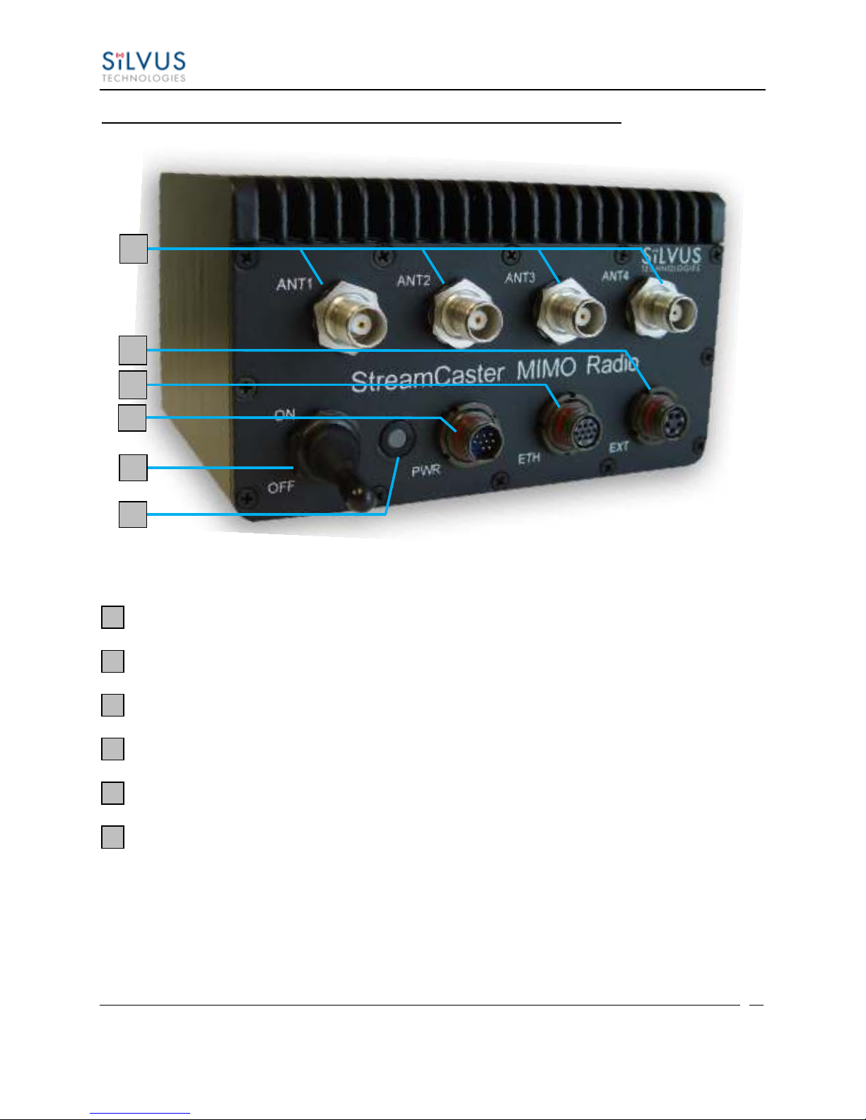
SC3500/SC3800 with EXT Connector (PA Faceplate Option):
Figure 3 StreamCaster 3500/3800 Ruggedized Enclosure
RF channels 1-4 connectors [TNC Female]
EXT PA Connector [Mighty-Mouse 801-010-07NF7-25SA]
Ethernet connector [Mighty-Mouse 801-010-07NF7-10SA]
Power (9-20 VDC) and Serial Port connector [Mighty-Mouse 801-010-07NF7-10PA]
Power Switch
Tri-Color Status LED (See Section 10.1 for Troubleshooting Information)
Red –Radio is in the process of booting up
Orange –Radio is fully booted but not wirelessly connected to any other radio
Green –Radio is wirelessly connected to at least one other radio
Flashing Red –Radio has recovered from a bad state and has reverted to factory
default settings
1
2
3
4
5
6
2
3
4
1
6
5

StreamCaster MIMO Radio User Manual 3/17/15
10017C000 Silvus Technologies Confidential Page
12
4.1 Connector Pinouts
4.1.1 SC3822 Pinouts
SC3822 Power/Ethernet/Serial Connector Pinout
Enclosure PWR/COMM
(LF10WBRB-12PD)
Signal
Switchcraft Pinout
(EN3C2F16X)
1
3.3V OUT
NC
2
GND IN
2
3
GND IN
2
4
VCC IN
1
5
VCC IN
1
6
100-Base T ETH0 M2N
NC
7
100-Base T ETH0 M2P
NC
8
100-Base T ETH0 M1P
NC
9
RS232_RXD
NC
10
RS232_TXD
NC
11
RS232_GND
NC
12
100-Base T ETH0 M1N
NC
Table 2 SC3822 Power/Ethernet/Serial Connector Pinout
SC3822 RS-232 and PS/2 (GPS) Pinout
RS-232
PS/2 (GPS)
Signal
Switchcraft Pinout
3
4
TxD
2
2
5
RxD
1
7
NC
RTS
4
NC
2
3.3V Out
6
8
NC
CTS
5
5
1
Ground
3
Table 3 SC3822 Serial and GPS Pinout
SC3822 USB/GPIO Connector Pinout

StreamCaster MIMO Radio User Manual 3/17/15
10017C000 Silvus Technologies Confidential Page
13
Enclosure USP/GPIO
(LF10WBRB-12PD)
Signal
1
USB_GND
2
USB_D-
3
USB_5V
4
NC
5
GPIO1 (PA Enable 3.3V)
6
GPIO2
7
GPIO3
8
3.3V
9
GND
10
USB_Sense
11
USB_D+
12
GPIO4
Table 4 SC3822 USB/GPIO Connector Pinout
SC3822 Extension Connector Pinout
Pin #
Signal
Notes
1-6
VCC_IN
9V - 36V. These pins are directly wired to the VCC_IN on FPC 1.
7-10
GPIO1 –GPIO4
These GPIOs are directly wired to the GPIOs on FPC connector 2.
11-19
Reserved for Testing
Do Not Connect
20
CPU Reset (3.3V)
Wired to PS_SRST_EXT signal on FPC 1
21-54
Reserved for Testing
Do Not Connect
55
GND
56
ETH1_MX4N
Second Gigabit Ethernet Interface
57
ETH1_MX4P
58
ETH1_MX3N
59
ETH1_MX3P
60
ETH1_MX2N
61
ETH1_MX2P
62
ETH1_MX1N
63
ETH1_MX1P
64
GND
65-68
Reserved for Testing
Do Not Connect
Table 5 SC3822 Extension Connector Pinout

StreamCaster MIMO Radio User Manual 3/17/15
10017C000 Silvus Technologies Confidential Page
14
Figure 4 SC3822 Power/Serial/Ethernet Pinout Diagram (Cable Side)

StreamCaster MIMO Radio User Manual 3/17/15
10017C000 Silvus Technologies Confidential Page
15
4.1.2 SC3500/SC3800 Pinouts
SC3500/3800 Power Connector Pinout
Enclosure Pinout
(801-010-07NF7-10PA)
Signal
Switchcraft Pinout
(EN3C2F16X)
1
12V Power Return
2
2
12V Power Return
2
3
12V Power
1
4
12V Power
1
5
TxD
For Serial Comm.
6
RxD
For Serial Comm.
7
RTS
For Serial Comm.
8
CTS
For Serial Comm.
9
Ground
For Serial Comm.
10
3.3VDC Out
3.3VDC for GPS
Table 6 SC3500/SC3800 Power Connector Pinout
SC3500/3800 Ethernet Connector Pinout
Enclosure Pinout
(801-010-07NF7-10SA)
Signal
RJ45 Pinout
1
WHT/BLU
5
2
WHT/BRN
7
3
BRN
8
4
ORG
2
5
WHT/GRN
3
6
WHT/ORG
1
7
BLU
4
8
GRN
6
9
NC
NC
10
NC
NC
Table 7 SC3500/SC3800 Ethernet Connector Pinout

StreamCaster MIMO Radio User Manual 3/17/15
10017C000 Silvus Technologies Confidential Page
16
SC3500/3800 EXT Connector Pinout (PA Faceplate Option Only)
Enclosure Pinout
(801-010-07NF7-25SA)
Signal
1
PA On (+3.3V)
2
Ground
3
LED1 (Black)
4
LED2 (Green)
5
LED3 (Red)
Table 8 SC3500/SC3800 EXT Connector Pinout
SC3500/3800 RS-232 and PS/2 (GPS) Pinout
RS-232
PS/2 (GPS)
Signal
Switchcraft Pinout
3
4
TxD
2
2
5
RxD
1
7
NC
RTS
4
NC
2
VCC (3.3V)
6
8
NC
CTS
5
5
1
Ground
3
NA
NA
LED Ground
NA
NA
NA
Green
NA
NA
NA
Red
NA
Table 9 SC3500/SC3800 Serial and GPS Pinout

StreamCaster MIMO Radio User Manual 3/17/15
10017C000 Silvus Technologies Confidential Page
17
Figure 5 SC3500/SC3800 Power/Serial Pinout Diagram (Cable Side) for GPS (Top) and RS-232 (Bottom)

StreamCaster MIMO Radio User Manual 3/17/15
10017C000 Silvus Technologies Confidential Page
18
Figure 6 SC3500/SC3800 Ethernet Pinout Diagram (Cable Side)
Figure 7 SC3500/SC3800 EXT Pinout Diagram (Cable Side)
Table of contents
Other Silvus Radio manuals


