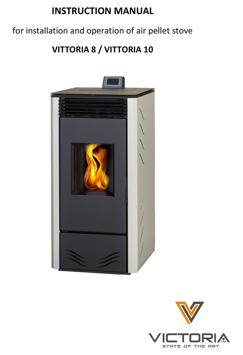
Victoria-05 Vittoria B Series User guide

1
Instruction
for installation and operation
of pellet burning stove with integral water boiler
VITTORIA В*

2
Contents
1. Introduction: …………………………………………….……………………………………….. 3
2. Safety information: …………………………………….…………………..…………………. 3
3. Technical parameters: ………………………………….…………………..……………….. 4
4. Safety devices: ……………………………………………….………………………………….. 6
5. Electronic circuit board: ………………………………….………………..……………….. 6
6. Principle of operation: …………………………………….………………………….……… 7
7. Operation ………………………………………………………….……………………..………… 8
8. Safety and detection devices: …………………………….…………………….………… 8
9. Components: ……………………………………………………….…………………….………. 8
10.Installation: ………………………………………………………….……………………….……. 9
11.Basic instructions for use: ……………………………………………………..…………… 11
12.Instructions for use: …………………………………..………………………………………. 12
13.Operating modes: …………………………………………………………………………….... 12
14.Maintenance: ………………………………………………………………………….…………. 14
15.Possible troubleshooting: …………………………………………………….…………….. 15
16.Check list: …………………………………………………………………………………………… 17
17.FAQ: ……………………………………………………………………………………….………….. 17
Declaration of performance: ……………………………….…………………………….. 18
Warranty conditions: …………………………………………………………………………. 19
Warranty card: …………………………………………………………………………………… 19

3
1.Introduction:
We congratulate you on the excellent choice! We wish you many pleasant moments with your new
pellet stove.
Do not leave the instructions unread. The installation and exploitation of the pellet stove should be made
in accordance with different legal obligations, which are explained in this instruction. According to the laws and
regulations for safety, when using an appliance of such class, the buyer and the user are obliged, with the help of
this instruction, to inform themselves for the assembling and the right operation of the appliance.
The manufacturer cannot be held liable for any damage caused as a result of incorrect installation,
incorrect maintenance procedures and improper use.
Your pellet stove is manufactured and tested in accordance with the requirements of the following
standards: EN 14785 EN 60335-1, EN 60335-1-102, EN 55014-1, EN 61000-6-1, EN 61000-6-3 and it is in accordance
with the approved technical documentation.
The appliance is not designed to be used by children and persons with limited physical, sensuous and
mental abilities, or by people with not enough experience and knowledge, except in cases when they are
watched and instructed how to work with this type of heater, by someone who is responsible for their own
safety
The pellet stove can be used and maintained only by adults who are familiar with the instruction manual.
2.Safety information:
The pellet stove must never be made to operate without water in the system or at a pressure less than 1
BAR. The stove can be damaged if it is ignited or used with no water in the system.
The stove is designed to heat water by means of automatic combustion of pellets (wood with 6 mm
diameter) in the combustion chamber
If not allowed fuels are used the warranty will void.
Please pay attention during the operation of the appliance children to be kept away from it, because stove
surface is too hot. Incineration danger!
The hazard which can come from not following the instruction manual: direct contact with electrical
(internal) parts, contact to the flame or with hot surfaces or when using un-allowed fuel.
If there is a malfunction in some part, the stove has safety devices which guarantee that it will automatically
shut down. The safety devices are activated automatically without any additional intervention.
In order to function correctly, the stove must be installed in accordance with the instructions given here.
Whilst functioning, the door must never be opened. The combustion is fully automatic and requires no
manual intervention
It is absolutely forbidden to use the stove if the glass is damaged or broken.
The handle of the fire door is becoming as hot as the front part of the stove. The heat resisting glove should
be used when using the handle.
Is is strictly forbidden that any foreign substances be put into the combustion chamber or in the hopper.
Do not use flammable materials when cleaning the flue outlets.
Before cleaning or maintaining switch of the stove from electrical supply.
Use a vacuum cleaner to clean the fire chamber and hopper only when the stove is cold.
Never use water to clean the inside parts of the stove.
The glass can be cleaned when cold with a suitable product and a cloth. Do not clean when hot.

4
Durring the stove is in operation, the exhaust pipes and door become very hot.
Do not place anything that is not heat resistant near the stove.
NEVER use liquid fuel to ignite the stove or rekindle the embers
Do not obstruct the external air inlets in the room where the stove is installed, or those of the stove itself.
Do not wet the stove and do not go near electrical parts with wet hands.
Do not use reducers on the smoke exhaust pipes
The stove must be installed in a room that is suitable for fire prevention and equipped with all that is
required (power and air supply and outlets) for the stove to function correctly and safely.
The stove must be kept in a room where the temperature is above 0 °C.
Use appropriate anti-freeze additives for the water of the system.
Ensure that the temperature of the return water is at least 45 °C.
The identification label can be found at the back of the stove.
Keep these instructions, the guarantee booklet and receipt of purchase, as they must be used when
requesting information.
If ignition fail, DO NOT re-ignite until you have emptied the combustion
chamber
.
ATTENTION:
THE
PELLETS
EMPTIEDFROMTHE
COMBUSTION CHAMBER
MUSTNOTBE
DEPOSITED INSIDE
THEHOPPER
3.Technical parameters:
Picture 1
А- Air intake Ø5см
В- Coupling RS 232
С- Smoke outlet Ø8см
D- ON/OFF switch with electric socket.
E- Water pump
F- Inlet cold water- G ¾ ‘’
G- Outlet hot water- G ¾ ‘’
H- Outlet pipe of the safety valve - G ½ ‘’
I- Button /with safety cover/ for thermostat reset

5
Technical and heating parameters:
Specifications:
Performance parameters:
Distance to flammable materials
Minimum distance, in mm.
side=400
back=400
front=800
Flue outlet
Ø 8 cm
СО emissions [13% О2]
0,0132 %
Output flue gas amount
12,23g/s
Working pressure of the water
1,5 bar
Maximum test pressure of the water
3 bar
Output flue gas temperature during nominal
power
108 °С
Heating output
Nominal heating output
18 kW
Radiant heating output
2 kW
Water heating output
16 kW
Minimal/Maximal autonomy
4,9/17,5h
Water boiler capacity
22 l
Extension tank capacity.
8 l
Water connection dimensions
3/4"
Type and size of the fuel
Pellets Ø 6mm
Fuel consumption min/max
1,2/4,3 kg/h
Hopper capacity
25 kg
Efficiency
92 ,4%
Maximal draught
12 Ра
Heating capacity
470 m3
Gross weight
288 kg
The heatable room dimensions are calculated on the basis of pellets with an heating value of at least 4300 kcal/kg and
heating loss of the room of 33 Kcal/m³h.
It is also important to consider the position of the stove in the room to be heated.
It is also very important the capacity and efficiency of the system heaters.
Please note that external devices may cause interference.
Warning: work on live components, maintenance and checks must be performed by qualified personnel. (Before
carrying out any maintenance, disconnect the device from the main power supply).
Electrical characteristics:
Performance parameters:
Power supply
230Vac+/-10% 50Hz
ON/OFF switch
Yes
Average power consumed
120 W
Average power consumed durring ignition
400 W
Radio control / Remote control frequency
Radio waves 2,4 Hz / infrared
Main power supply protection
Fuse 2А, 250VAC5х20
Electronic control board protection
Fuse 2А, 250VAC5х20
The producer reserves the right to make changes to these products to improve their performance with no prior
warning.

6
4.Safety devices:
-Thermocouple:
Placed at the smoke outlet to detect temperature. Turns the stove on and off and also controls its operation based
on defined parameters.
-Vacuum gauge: (electronic pressure sensor)
Placed on the smoke extractor which detects the vacuum value (compared to the installation enviroment) in the
combustion chamber
-Safety thermostat:
Switches off when the temperature in the stove is too high.
It stops pellet loading which is causing the stove to shut down. It has to be reset manually.
-Tank safety thermostat:
Switches off when the temperature in the stove is too high.
It stops pellet loading which is causing the stove to shut down. It has to be reset manually.
-Fuse:
At the back of the stove are placed 2 fuses. One in the button with socket and one for spare.
5.Electronic circuit board:
Scheme 1
1.smoke extraction motor control
2.inlet air sensor
3.thermoregulator exit water
4.vacuum gauge
5.outlet air sensor
6.power supply
7.ignition unit
8.sensor tº hopper housing
9.thermal limiter tº outlet water
10.hopper
11.pump
12.smoke extraction motor
13.electric wire - black
14.electric wire - black
15.electric wire - brown
16.control panel
17.socket

7
The pellet stove is equipped with system which ensures optimal burning.
The system ensures excellent operation thanks to two sensors measuring the pressure level in the
combustion chamber and smoke temperature. The detection of and subsequent optimisation of these two
parameters is continuous in order to correct opera- tion anomalies in real time.
The system offers constant combustion, automatically regulating the draft based on the characteristics of the
chim- ney flue (bends, length, shape, diameter, etc..) and environmental conditions (wind, humidity,
atmospheric pressure, installations at high altitude, etc.). The standards for installation must be respected.
The system is also able to recognise the type of pellets and automatically adjust the flow moment by moment to
ensure the required level of combustion (use wood pellets with a diameter of approximately 6 mm).
6.Principle of operation:
Picture 2 Picture 2.1
The stove is fuelled by pellets. These are little, cylindrical shapes of pressed wood whose combustion is
controlled electronically. The heat produced by combustion is mainly transmitted to the water and partly
emitted into the room by
radiation
.
The fuel tank - hopper (А) is located at the back of the stove. Loading the tank is thru the back of the lid at the
rear of the top. The fuel (pellets) is taken from the tank (A) and via an Archimedes screw (В) powered by
electric gear motor (С) is transported to the combustion chamber (D).
The ignition of the pellets as made by air, heated by electrical heating element (Е) which is sucked into the
combustion chamber by the smoke extractor (F).
The combustion air is drawn into the room (where there must be an air intake) smoke extractor (F).
The smoke produced by combustion, is extracted from the stove through the smoke extractor (F) and expelled
from the pipe union located in the bottom part of the rear of the stove.
The ash falls under and beside the crucible in which is housed an ash tray from which the ash must be
periodically removed by vacuuming when cool.
The hot water produced by the stove is transferred by circulation pump build in the stove to the system.
Filling and empting of the system is made by build in valve and control manometer Picture.2.1.
The stove is designed to function with closed expansion tank (Н) and pressure valve, both of which are built in.
Fuel quantity, smoke extraction/combustion air supply and pump activation are regulated by the control
board, which is equipped with software to achieve high combustion efficiency and low emissions. The control
panel (G) is placed on the top of the stove and can control, check and see all phases from the work of the
stove.
C
G
A
F
D
E

8
7.Operation:
The required temperature of the water in the system is adjusted and set by the control panel (recommended
70oC) and the stove manually or automatically changes the power to reach and keep the temperature.
Fuel notes:
- The stove is designed and programmed to use and burn wood pellets with diameter 6 mm.
- The pellets are type of fuel which is made from heavily compacted under very high presure chopped waste
wood and saw dust. There are no additional or foreign materials used. They are with small size of
approximately 6 mm in diameter with cylindrical shape. For the normal and proper work of the stove you must
not burn any other materials or fuels. Using other materials (including wood) will cause warranty void. The use
of such materials is detected by laboratory analys.
The stove is produced, tested and programmed to operate with pellets with the following specifications:
-diametter: 6mm
-length maximum: 40mm
-maximum moisture content: 8%
-caloric value: minimum 4300 ccal/kg
Using inappropriate pellets can cause: clog of the burner, decreased efficiency and power, clogging dirt on the
glass, increased the fuel consumption (cause of the not proper burning), blocking the hopper which can cause
the stove to stop.
Warning! For proper burning process, the pellets have to be dry and stored in dry rooms with enough air
ventilation.
8. Safety and detection devices:
Smoke thermocouple.
It is located at the smoke exhaust to measure the temperature. It is also controlling the ignition and if the
temperature is too high or too low it triggers shut down sequence (Stop Flame ).
Hopper with safety thermostat.
Located near the fuel tank. If the temperature is too high it cuts out the electrical supply to the motor.
Sensor for temperature of the water.
It is measuring the temperature of the water inside the stove and sends information to the control module. If
the temperature is too high it triggers block phase.
Safety thermostat for overheating protection of the water with manual reset.
Measures the temperature inside the stove. If the temperature is too high the electric supply to the motor is
disconnected. If it has been triggered, it has to be reset manually by the button at the back of the stove
/Picture 1 possition I/
Overpressure valve.
When reaching the pressure mentioned on the label, the system is activated and drains water. After that the
water has to be topped up.
Warning! Remember to connect the stove to the sewage system.
If the stove is blocked and stop working the reason will be displayed and stored in the memory.
9. Components:
Resistance (igniter)
Triggers combustion of the pellets. It remains on until the temperature increases with 15oC compared with the
moment of ignition
Smoke extractor
Pushes the smoke to the smoke outlet and draws out combustion air by vacuum.
Gear motor
Activates the feed screw, which allows the pellets to be moved from the hopper to the combustion chamber.
Pump (circulator pump)
Pushes the water to the system.

9
Closed expansion tank
Absorbs the differences in the volume of the water caused by the heating.
Technician has to decide is it needed to add second tank to the existing one, depending from the volume of
the water in the system.
Venting valve (deaerator)
Positioned on the top part, allowing to bleed the system from any air inside, present during filling with water.
Picture.3
10.Installation:
Warning!
Installation of the stove and the heating system should be made by authorized and licensed organization!
The manufacture of the stove does not guarantee the proper working of the installation. The guarantee is
only for the stove.
Any maintains, check-ups and work on the electrical components should be made only by authorized
personal. Before any work on the stove disconnect from the electric supply.
Refer to any local regulations valid for your country if you don’t find the required information in this
instruction manual.
It is forbidden to install the stove in bedrooms, bathrooms and in rooms in which there is already installed
another heating appliance. If there is already installed heating appliance, it has to be with separate air supply.
Verify compatibility with other devices.
The stove must not be installed in the same room in which are installed air extractors types A and B, gas
appliances or any devices which are reducing the ventilation in the room.
Check all electrical connections. The electric socket should be positioned in easy to reach and access place.
The stove is equipped with electric cable to be connected to a 230V 50Hz socket. Any variations in the voltage
above 10% can cause malfunction in the appliance (unless the appropriate differential switch is installed). The
electrical system should be in accordance with all local regulations and laws, especially regarding the earthing.
In accordance with the regulations for connecting to the electrical system, the stove should be mounted in a
proper way which can guarantee easy access to electric socket (230V 50Hz). It is forbidden to install the stove
in rooms where the electrical system is on the floor.
Any lack of efficiency in the electrical system or “ground” circuit can cause malfunction for which the producer
cannot be held responsible.
Positioning:
The stove must be leveled when installed. The floor must be even, horizontal and made by fireproof materials.
If the floor is not fireproof (carpet for example) there must be used fireproof base made by steel, glass or
stone plates.
Safety distances for fire preventing:
The stove must be installed in accordance with the following safety requirements:
-Medium flammable items must be kept in distance minimum 40 cm. from the back and the sides of the
stove.
-Easily flammable items must be kept in distance minimum 80 cm. in front of the stove.
-If the stove is mounted on easy flammable floor, there must be placed a sheet of heat insulation under
the stove. It must be extended above the base of the stove with more than 20 cm at the sides and more than
40 cm in front.
Flammable objects must not be placed above the stove or at a distance that is any less than the above
mentioned safety distances. If connected to wooden walls or other flammable materials, the smoke exhaust
pipe must be appropriately insulated with ceramic fibre or other similar material.
Air inlet:
Warning! Incoming air must be ensured.

10
The room where the stove is placed must have an air inlet with a cross-section of at least 80 cm² so as to
guarantee sufficient air supply to the stove for combustion. Alternatively, the stove air may be taken directly
from outside through a 5 cm steel extension of the pipe. In this case, there may be condensation problems
and it is necessary to protect the air intake with a grille, which must have a free section of at least 12 cm². The
pipe must be less than 1 metre long and have no bends. It must end with a section
at 90° facing downwards or be fitted with a wind guard.
Smoke outlet:
It is forbidden to lead out the smoke from the stove directly thru the wall in the atmosphere. There must be
smoke pipe or chimney which will lead the smoke to a safety for the health height.
It is recommended to install the stove as closest possible to a chimney. This will reduce the need of smoke
connecting pipes.
The discharge system must only be used for the stove (the chimney must not be used by other appliances).
The smoke goes thru 8 cm in diameter outlet at the back of the stove. T-junction connector with condensation
collector must be ensured and installed at the beginning of the vertical section. The stove smoke discharge
must be connected with outside by means of steel or black pipes with certification ЕN 1856. The pipes must be
hermetically sealed. The pipes must be isolated and sealed with heat resistant materials (high temperature
silicone or mastic). The only horizontal section allowed may be up to 2 m long. The horizontal section must
have a minimum inclination of 3% and a maximum of two 90° bends. If the outlet is not fitted into a chimney
flue, a vertical section of at least 1.5 m will be required, complete with a wind guard. The vertical duct can be
internal or external. If the smoke channel is outside, it must be insulated. If the smoke channel is fitted inside
a chimney flue, the latter must be suitable for solid fuel. If it is wider than 150 mm in diameter, a pipe must be
entered and the outlet sealed to the masonry. All sections of the smoke duct must be accessible for inspection.
At the bottom part of the chimney there should be a revision opening, allowing periodically cleaning, which
should be made at least once per year. According to the existing standards at the top of the chimney pipe a
wind resistant element must be installed.
Picture 4
А: insulated steel chimney.
В: minimum height 1.5 m. Beyond the roof eaves.
С-Е: air inlet from outside (thru section of at least 80 сm2)
D: steel chimney in already existing masonry chimney.
Hydraulic connections
The stove is equipped with water boiler with capacity of 22 l. This significant amount of water, renders the
stove very smooth during operation. Also providing excellent burning process and excellent results.
WARNING!!! The stove must never be made to work without water in the system or at a pressure under 1
bar. If ignited without water in the system the stove can be heavily damaged.
All hydraulic connections must be completed by authorized specialists, which can issue a certificate. Other
check-ups can be also performed in accordance with the law and requirements valid for the country in which
the stove is used.
Practical notes:
1) Consider appropriate solutions when connecting the supply water, return water and drain, which will
make more easy the moving of the stove if it is ever needed.
2) To improve the work of the primary circuit (where there is a heat generator) must be separated from
the secondary.

11
Water treatment.
Consider and ensure adding the appropriate antifreeze or other compounds against freezing and corrosion. If
the water is exceeding the hardness value of 35˚F, you should use water softener.
Note: the person responsible for the heating system should consider and ensure additional heat extension
tank depending from the system.
Warning! It is required to install filter for the incoming water. Failure to do that will cause warranty void of
the water pump.
Warning:
When producing water for sanitary needs, the power output of the radiators will decrease.
First start up (made by the dealer):
Make sure that the heating system is well assembled and equipped with expansion tank which is appropriate
for the safe work of the system. The presence of heat expansion tank in the stove itself, does not guarantee
adequate protection from overheating the water.
- Cconnect the stove to the electrical system and make a cold test.
- Fill up the system thru the inlet valve (recommended pressure 1 bar)
- During the filling bleed the pump manually and open the manual vent /Picture 3/
- These actions must be carried subsequently periodically.
11.Basic instructions for use:
Command board:
ляв дисплей
приемник на сигнал от дистанционното
десен дисплей
зарежзане/резерва бойлер
Picture 5
1. Button turn on or off (hold down for 2 sec.) and for exit during programming mode.
2. Button allow access to programming menu.
3. Button increasing various settings.
4. Button decreasing various settings.
5. Button pellet loading / button for reserve. Press once to update the memory of the stove that the
tank is loaded with 15 kg pellets. This will allow the stove to monitor the remaining quantity in the tank.
6. Button boiler settings. This button together with the +/- keys controls the secondary circuit e.g.
boiler. The right side of the display shows the temperature of any existing connected storage tank/boiler
(if the boiler sensor is connected). Press the button to see and set the value. If the boiler sensor is not
connected the following image will appear „--- оС”
First ignition:
The first start up must be done by the dealer.
Consult your dealer when starting up the stove for the first time to calibrate the stove with the pellets
used
The dealer must:
Load / Reserve
Boiler
Right display
Left display
Remote control receiver

12
-Check and verify the correct installation of the components in the system and also is the system
equipped with appropriate expansion tank to ensure safe work. The presence of heat expansion tank in the
stove itself, does not guarantee adequate protection from overheating the water.
-Connect the electric supply and make a cold test (performed by the dealer)
-Fill up the system form the filling tap (recommended not to exceed 1 bar pressure.)
During filling up the system, bleed the circulation pump.
Warning !
During first start up purge the system using valve at the top of the stove. This operation must be
performed again in the first days of use and when the system is topped up. The presence of air in the system of
pipes could result improper work of the appliance. For easier work, there is a plastic tube available to the valve.
The stove is painted with heat resistant paint. The paint is resistant to high temperatures, but it is not
resistant to rust. Please do not place any objects on the stoves paint. If there is a dust, the cleaning must be
done with smooth brush. Never use water or cloth!
During the first ignition it is necessary to “bake” the paint to harden it. This must be done with very slightly
opened door. During this procedure, do not put anything on the stove and do not touch the external parts to
avoid damaging the paint. There will be slight smell, which is a result from the paint hardening. This is normal
and will disappear in few hours. Please unsure good ventilation in the room during this procedure.
If in a result of overheating or not proper use the color is changed, there are spots of rust or there is damage on
the paint, do not worry. You can order the proper spray paint to your dealer.
Before igniting please check:
The installation is correct. Check the electric supply; the door is closed with proper seal; the combustion
chamber is clean; the display is on stand-by (time and date set)
12.Instructions for use:
Feeling the feed screw:
When the tank for pellets is completely empty this means that the feed screw is also empty. Before re-igniting
the stove you must fill it up following the next steps: press buttons +/- simultaneously (by the control panel) for
a few seconds. After the keys are released in few seconds “Reload” will appear. It is normal some pellets to
remain in the hopper, because the screw wasn’t able to pick them up. Once a month vacuum the hopper to
prevent clogging from dust.
During the first start up of the stove (or after reloading pellets when completely emptied) it is possible the start
up procedure to be repeated.
Automatic ignition:
When the stove is on stand-by position, press button 0/1 for 2 seconds (via remote control or control panel).
This will trigger the ignition process. “Start” will appear on the display and countdown will be started in seconds
(1020). There is no time to adjust the ignition process: the duration will be automatically shortened if the
control board detects that certain test are performed previously. The flame will appear in 5 minutes
Manual ignition (in case of start-up failure)
If the temperature is lower than 3 ˚С it is too low for the igniter to heat up enough to start the fire or if the
resistance is temporary not working, you can use a firelighter to ignite the stove.
Place the firelighter in the combustion chamber, close the door and pres 0/1 on the control panel (or on the
remote).
13.Operating modes:
Working with the control panel, when the stove is working or in stand-by position.
-press: + or –button, to increase or decrease the desired temperature of the water.
-With pressing the “boiler” button you can change and set the desired temperature in the boiler or with
+/- to change the temperature of the secondary circuit. It is possible to see (if the boiler is connected) the
temperature of the boiler or external storage by pressing the boiler button and the previously set temperature
will be displayed. By pressing +/- you can change the parameter. If the boiler sensor is not connected the
following will appear on the display. “--.- ˚С”.
Shutdown:

13
When the stove is operational by pressing button 0/1 for 2 seconds, the process for shutting down the stove is
started and OFF is displayed for 10 minutes. Shutdown phase includes:
-Pellet feeding is stopped.
-Stopping the circulation of the water.
Never pull off the plug during shutdown process!
Please have a note that the circulation pump will work till the temperature of the water drops under 40oC.
Setting the clock:
Press “MENU” button for 2 seconds and use +/- buttons to follow the instructions shown on the display. Access
clock menu. This menu will allow you to change and set the time. After that press “MENU” and the following
information will appear, and can be adjusted: day, month, year, hour, minutes, day of the week. When “Save?”
appears, you can chesk is everything entered correctly before confirming. Press “MENU” to confirm and save
the information („Save OK „ is show on the display).
Programming for igniting and shutting down of the stove at different time in the week.
Press “MENU” for 2 seconds, to enter in time setting menu and press + button to enter in weekly timer function.
“Program ON /OFF” ще will appear on the display. This timer allows you to set number of ignitions and
shutdowns per day (up to three) for each day of the week. After confirming with “MENU” button one of the
following options will appear:
-No Prog. (no program is set);
-Program/daily (a single program is set for every day)
-Program/weekly (a program is set for each day of the week.)
You can change to every menu by pressing +/- buttons.
Press “MENU” to confirm “Daily Program”and access to few programs (ignition/shutdown) to be set per day.
Use Program/daily option to set the same program for each day of the week.
The following will appear on the display if + is pressed:
-No Prog.
-Prog. No 1 (one ignition and shutdown per day) Prog. No2 (same as before)
Prog. No3 (same as before)
Use the button to show them in reverse order. If you choose the first program the time of ignition will be
shown.
The display shows: 1 ignition hour 10:30; use the +/- buttons to change the hour and press “MENU” to confirm.
The display shows: 1 ignition minutes 10:30 use the +/- buttons to change the minutes and press “MENU” to
confirm
Shutdown time is set by the same way.
The programs are set and by pressing “MENU” button when “Save” is shown on the display.
To confirm program Program/week you need to choose the day to which the program apply.
1 Mon, 2 Tues, 3 Wed, 4 Thurs, 5 Fri, 6 Sat, 7 Sun
When you have chosen the day by pressing +/- buttons, press “MENU” to confirm and continue with the settings
in the same way as for Program/daily, selecting whether or not to enable a program for each day of the week
and choosing the number and times of interventions..
If you made a mistake during programming you can exit without confirming the settings by pressing 0/1 and
Save will be shown on the display.
If the stove runs out of pellets the stove will block and Stop/Flame will be shown on the display.
Pellet reserve warning.
The stove is equipped with electronic system to monitor the pellets. The system is integrated in the control
module, which allows the stove to monitor how many pellets are left in the hopper. While the stove is working
the check up is made constantly.
For proper work of the system it is important to follow the procedures during first ignite (made by the dealer).
Before the system for monitoring start working, you have to load and use full stack of pellets. This will allow
brief running of the loading system. Subsequently load 15 kg pellets.
Then press once the “reserve” button to confirm and save in the memory that you have load 15 kg pellets in the
hopper.

14
From this moment the display will show the remaining quantity of the pellets in kg. (15 … 14 … 13). Every time
when pellets are loaded you must enter the quantity. When loaded 15 kg. just press “pellet load” button. For
different quantity or if there is a mistake, you can specify the quantity by using the menu as follows:
Press “MENU” for 2 seconds to view the Settings
Use + or –to reach T.Max exit
Confirm by pressing “MENU” button and the remaining quantity with pellets will be shown on the display + what have been
loaded.
If the hopper is left without pellets, the stove will block and “Stop/ Flame” will appear.
14.Maintenance:
Before any maintenance procedure, disconnect the electric supply.
Remember, that is very important to vacuum the combustion chamber before every ignition.
If by any reason the ignition fail, do not restart until you empty the combustion chamber.
Warning: pellets which are removed from the combustion chamber must not be returned to the hopper.
For the proper work of the stove, regular maintain is required.
The stove will show the following message „smoke ˚C /high” or “Maintain” when it is needed cleaning. This is
preceded by “Clean exchang” message on the display.
If regular maintenance is not performed and at least once a season don’t make a complete cleaning, could cause
to poor functionality. Any problems resulting from lack of maintenance will immediately void the warranty.
Daily maintenance:
The cleaning must be performed with vacuum cleaner when the stove is completely cold. The whole procedure
takes only few minutes.
The cleaning rods (elements) must be moved once a day with the help of handle.. This will help to save fuel. The
handle is located in the top side near the pellet tank –Picture 6. Use glove during operation.
Picture 6 Picture 7 Picture 8 Picture 9
Operations which must be made when the stove is cold:
-Open the fire door and clean the ash from the ash pit. (Picture 7);
-Remove the combustion chamber or use spatula to scrape it and clean any blocked holes Picture 8;
-Vacuum the combustion chamber and clean the contact edges.
-When cold clean the glass if necessary.
Never vacuum hot ash or pellets. Failure to do that will cause damage to the vacuum cleaner.
Weekly maintenance:
-Empty the hopper and use vacuum cleaner to clean it when the stove is not been used for a long
period of time or when it is used once every 15 days.
-Clean the heating element –Picture 9.
Cleaning of the smoke duct:
When the stove is not in operation and cold move the cleaning rods energetically (Picture 6); open the left and
right service openings (Picture 10 and 11) and clean with vacuum cleaner.

15
Picture 10 Picture 11
The amount of dust depends from the used fuel.
Failure to do the cleaning procedure can cause the stove to block.
After the cleaning procedure is completed, make sure that all service openings are closed and sealed properly.
Seasonal maintenance (performed by the dealer):
The dealer firstly is setting the amount of pellets consumed after which the message “Maiten??” appears on the
display. The stove is continuing normal operation, but the end client must contact the dealer to perform the
necessary seasonal maintenance. The end client is invited to perform seasonal maintenance regardless of which
messages may appear on the display.
Before performing any maintenance procedure, disconnect the stove from the electric supply.
-Clean the stove outside and inside.
-Carefully clean the tubes of the heat exchanger.
-Carefully clean and remove dirt from the combustion chamber and the relative compartment.
-Clean the motors, verify mechanical and clam loosening.
-Clean smoke channel (replace seals on pipes) and smoke extraction fan chamber.
-Check the expansion tank.
-Check and clean the circulator.
-Check the sensors.
-Check and if necessary replace the clock battery on the control board.
-Clean, inspect and scrape any residue from the ignition resistance compartment and if necessary,
replace it.
-Check and clean the control panel and display.
-Check all electric cables.
-Clean the pellet hopper and check loosening of the feed screw - gear motor assembly.
-Check and if needed replace the door seal.
-Make a functionality test: load the feed screw, ignite, let it run for 10 minutes and shutdown..
If the procedures for maintenance are not performed regularly, the warranty will void.
If the stove is used very often it is recommended to clean the smoke channel once every 3 months.
Warning!!! After completing cleaning procedure, inappropriate assemble (Picture 7) of the upper and lower
part of the combustion chamber can result a drop in stoves performance. Make sure that it is all correct
assembled before igniting.
When cleaning procedure is performed on the smoke ducts, consider the regulations regarding the individual
chimneys for generators running on solid or liquid fuel.
Maintenance and control:
The chimney to which the stove is connected must be cleaned at least once per year (please check is there an
additional regulation norm in your country).
If regular check-ups and cleaning procedures are not performed, the risk of fire inside the chimney increases.
If such a fire is started, do the following: do not use water; empty the hopper from the pellets; contact the
dealer before reigniting.
15.Possible troubleshooting
If there is a problem, the stove will automatically stop and start shutdown procedure. The display shows the
reason for the shutdown (see the various alarms below).
Never pull the plug for the electric supply during shutdown procedure!.
When there is an event of malfunctioning. To restart the stove it is necessary to wait the procedure for
shutdown to be completed (10 minutes with acoustic signal).
Do not start the stove before checking and if needed solve the problem for the stopping and clean the
combustion chamber.
Possible reasons for blocking: Indication and solution.
1. H2O PTC_FAULT: Shuts down due to the water temperature sensor being broken or disconnected.
- Check connection of the sensor to the control board. Verify functionality by means of a “cold test”

16
2. VERIFIC./EXTRACT: Shuts down due to the revolution sensor of the smoke extractor motor detecting an
anomaly.
- Check smoke extractor functionality (connection of the revolution sensor)
- Check smoke channel for dirt.
3. STOP/FLAME:Shuts down due to a drop in smoke temperature (intervenes if the thermocouple detects a
smoke temperature that is lower than that which is set, thereby interpreting it as a flame failure).
The flame may not go on for the following reasons:
- lack of pellets
- too many pellets in the combustion chamber have suffocated the flame
- the maximum thermostat / pressure switch / water safety thermostat has intervened to
‘stop’
the gear motor.
4. BLOCK_FI/NO START: Shuts down due to incorrect smoke temperature during ignition (intervenes if the flame
fails to appear within a maximum of 15 minutes, or if the ignition temperature is not reached).
There are two possibilities:
- 1. NO flame! Check:
- Combustion chamber –position and proper assembly.
- Correct work of the igniter.
- The temperature in the room. If it’s lower than 3оС use fire lighter.
- 2.There is flame but BLOCK_FI/NO Start is show on the display.
The dealer must check:
Proper work of the thermocouple.
Set correct parameters for temperature ignition.
5. Failure/Power: Shuts down due to an electricity failure.
Check electricity connection and drops in voltage.
6. FAULT /RC:Shuts down due to a failure occurring in the thermocouple or it being disconnected
Verify connection of thermocouple to the control board. Verify functionality in a cold test.
7. SMOKE OС/HIGH: Shuts down due to excessive smoke temperature
An excessive smoke temperature may occur because of the following: unsuitable pellet type, anomaly in smoke
extraction, blocked smoke channel, incorrect installation, gear motor ‘drift’.
8. H2O TEMPALARM: Shuts down due to water temperature being higher than 90 °C.
An excessive temperature may occur because of the following:
- system too small: ask the DEALER to activate the ECO function
- blockage: clean the exchanger pipes, the combustion chamber and the smoke outlet.
9. VERIFIC/AIR FLOW:Shutdown due to loss of vacuum (occurs if the flow sensor detects insufficient
combustion air flow). The air flow may be insufficient in the following cases:
- if the hatch is open or not properly sealed
- air suction or smoke expulsion problem
- combustion chamber clogged
- flow sensor dirty (clean with dry air)
- The vacuum alarm may even be activated during the start up phase.
10. „BATTERY CHECK” : the stove is properly working but the error is show on the display. The battery of the
circuit board needs change.
11. The pellets does not enter in the combustion chamber. Few reasons are possible:
- the feed screw is empty. Fill with pellets by pressing + and –buttons simultaneously.
The pellets are blocked in the hopper.
- use a vacuum cleaner to empty the pellet hopper.
The gear motor is broken. (there will be error message).
The feed screw safety thermostat ‘disconnects’ the electrical supply of the gear motor:
- check that it has not overheated. Use a tester or a temporary bridge to verify.
The water overheating safety thermostat ‘disconnects’ the electrical supply of the gear motor:
- check that the stove contains water.
- After having removed the protective cap, press the button on the back of the stove to reset
In this cases you must contact the dealer before restarting.
Note: all signals/warnings will remain shown until the control unit is used by pressing button 0/1. Do not use
the stove until you solve the problem. It is very important for the dealer to know the exact message/signal.
12. The display/control unit is off.
- check electric supply.
- check the fuse.
- check the connections of the flat cable.
13. The water is not hot enough:
- clean the heat exchanger.

17
16. Check list:
Positioning and instalation:
- Enough room ventilation.
- Only the stove outlet passes through the smoke channel/chimney.
- Smoke pipes have maximum 2 curves, maximum length 2 meters and at least 1,5 m vertical pipeline.
- The exhaust pipes are made by appropriate material (stainless steel recommended)
- When using any flammable materials (wood for example) all precisions have been taken to prevent fire hazard.
- The heating capacity has been properly calculated considering radiator efficiency and how many kW are
necessary.
- The whole system has been declared to be compliant the country regulations, norms and laws.
Use :
-The wood pellets use must be dry and with good quality (6 mm diameter) and maximum humidity 8%.
-The chimney, smoke pipes, the ash pit and the combustion chamber are well cleaned.
-The cleaning rods are moved every day.
-The pipes of the exchanger and all parts of the combustion chamber are well cleaned.
-The exhaust outlets are well cleaned.
-The system is bleed from air.
-The pressure is 1 bar (checked via manometer).
17.FAQ :
The following answers are indicative. For details refer to the instruction manual.
1. What to do and prepare in advance to install the stove.
The smoke outlet and chimney must be at least 100 mm. in diameter.
Air inlet in the room which is at least 80 cm2.
¾ ‘’ inlet and outlet connectors.
¾ ‘’drain connectors for overpressure valve.
¾ ‘’ connector for fitting.
Certified electrical connection: 230V +/- 10% 50Hz
2. Is it possible to use the stove without water?
NO. Using the stove without water will cause damage.
3. Does the stove produce hot air?
NO. Most of the heat is transferred by the water. Only small part of the heat is transferred to the room whre
the stove is installed by means of radiant heat from the glass. It is recommended to install radiator in the
same room.
4. Can I connect the inlet and the outlet of the stove directly to the radiators?
NO, as all other boilers it must be connected to a collector, from which the water is distributed.
5. Does the stove supply hot water for sanitary needs?
It has such possibility –installing serpentine in the boiler.
6. Can the smoke be discharged directly thru the wall?
NO,the discharge should be done in accordance with the existing standards, the exhaust pipe must be above
the roof and to operate correctly it should be at least 1.5m. high. Wind protector should be available.
7. Is it needed to have an air inlet in the room?
Yes, to replenish the air used during the burning. The smoke extractor is drawing air from the room to the
combustion chamber.
8. What settings are required on the display?
The requested temperature. The stove will adjust the power output in accordance with the desired
temperature. For a small systems, the stove can use mode in which the stove is ignited and shutdown after
the water temperature is reached. Dealer can adjust this function.
9. How often the combustion chamber should be cleaned?
Before starting the stove. Can do that only when the stove is off and cold and after we have cleaned the
pipes with the rod.
10. Do I have to vacuum the hopper?
Yes, at least once a month or when the stove is not used for a period of time.
11. Can I use different fuel except pellets?NO. The stove is produced and designed to use only pellets with 6
mm. diameter. All other types of fuel can cause damage.

18

19

20
Warranty conditions:
The producer guarantees the proper working of the stove in 24 months term from the day of selling in the store, except for the parts
which are consumptives, in case that all requirements for proper storing, transportation, installation and use are kept.
Installing of the stove and the heating system must be completed by authorized licensed organization in accordance with the
instructions given in this instruction manual!
When claiming the stove you must present receipt and invoice for buying the stove and the original of the warranty card.
Failure to present the above mentioned documents will cause warranty void and the repairs for the stove will be paid by the buyer.
The producer will accept all warranties except when one or more of the following situations occurs:
-there has been repairs or attempts for repairs done by the owner or by not authorized person;
-the requirements shown in the instruction manual for installation and use are not kept;
-damages caused during transport;
-inappropriate made heating calculations and project for heating system and installation of the stove;
-there have been made changes in the construction of the stove;
-warranty does not cover any damages caused be mechanical impact including broken glass.
The warranty will void for damages caused by external actions, weather, electricity failure, fire, natural disasters and any
malfunctions in the electric system.
-the claim is not accepted when there are defects, missing parts and others if by this reason the stove is with reevaluated price.
In case of any damage or claim, you must contact the dealer from which the stove is bought.
Warranty card:
WARNING! The warrantee is valid only if the warranty card is correctly filled, stamped and signed.
Production date ……………….. 201….
Factory № …………………………………….
Quality control check ……………………… (stamp)
The stove is sold in good operating condition
………………………………………………………………………………………………
(name of the buyer)
Residence address ………………………………. City: ……………………………………...
Trade company (purchased from) …………………….. City: …………………………..
Invoice № ………………………….. from ……………………………….
(date of purchase)
Buyer: ………………………………. Seller: …………………………….
(signature) (signature and stamp)
REGISTER
of done repairs during the warranty period
Service
Accepting date in
the service
Order №
Type of repairs
Date
Inspection made by
Table of contents
Other Victoria-05 Stove manuals
Popular Stove manuals by other brands

ADURO
ADURO P5 Series Technical maintenance manual

Cumberland Stove Works
Cumberland Stove Works MF3600G Installation and operation manual

HWAM
HWAM 3600 quick start guide

Hearth & Home
Hearth & Home pelpro PP60 Service manual

Olsberg
Olsberg Tolima PowerSystem Compact Instruction

KEDDY
KEDDY K700 installation instructions

Snappy Chef
Snappy Chef SCD003 user manual

Desa
Desa SVYD18N Series OWNER'S OPERATION AND INSTALLATION MANUAL

Camp Chef
Camp Chef Mountain MS2HP Care, use and safety instructions

MCZ
MCZ CLUB COMFORT AIR MATIC 14 M1 installation guide

VonHaus
VonHaus 2500454 quick start guide

Master Forge
Master Forge WS110 Operating instructions and owner's manual