Victron energy VE 5kVA User manual

Table of Contents
1. Introduction ........................................................................................................................... 1
2. Operation .............................................................................................................................. 2
3. Installation ............................................................................................................................. 3
4. Technical specifications ............................................................................................................ 5
5. Electrical diagram .................................................................................................................... 6
6. Dimensions ............................................................................................................................ 7
VE Transfer Switch

1. Introduction
The VE Transfer Switch is designed to take over automatic switching between different power sources. For example, between a
generator and the shore, between an inverter and a generator, or between an inverter and the shore.
It has two inputs and one output and automatically transfers the available AC power from one of the inputs to the output. It can be
used with any Victron Energy inverter, providing the inverter power rating does not exceed the transfer switch power rating.
The transfer switch can also be used to allow a MultiPlus inverter/charger to connect to two different AC sources, like shore power
and a generator, instead of only being able to connect to a single AC source.
VE Transfer Switch
Page 1 Introduction

2. Operation
The transfer switch is situated between a generator or shore power and the inverter.
If the voltage level or the frequency of the generator or the shore power varies on input 1, the transfer switch will switch to the
inverter on input 2.
Once the generator or the shore supply has remained continuously stable, the transfer will switch back to input 1 with a delay of
approximately 10 seconds. This way, the appliances that are connected to the output are protected against damage from voltage
drops.
During transfer between one of the power sources from input 1 to input 2 or vice versa, the appliances are not supplied with
power for a short time. Because of this, computers, electronic devices etc., that are connected to this group might lose data.
The transfer switch can be used with any type of inverter, but the best results, however, are obtained with an inverter from Victron
Energy.
VE Transfer Switch
Page 2 Operation

3. Installation
WARNING: Make sure that all AC power sources are switched off or disconnected before and during
installation.
Mounting:
• Install the transfer switch in a dry and well-ventilated area.
• To gain access to the transfer switch, remove the four screws in the front panel.
• The transfer switch can be wall-mounted by using the four holes in the rear of the casing.
Electrical connections:
• The input cables (mains/generator) and the inverter (or inverter/charger) and the output cable (to the appliances) should be
connected according to the connection diagram as shown below.
• The input and output cables must have the correct core thickness for a safe installation. Undersized cables can cause
overheating of the cables. The maximum cable core thickness is 6mm².
• Use the provided cable glands to pass the input and output cables through the casing.
• Tighten all connections with a nominal torque moment of 1.2Nm. This is to limit transition resistance as far as possible. Loose
connections can cause dangerous overheating of the terminals.
Connection diagram VE Transfer Switch 5kVA.Connection diagram VE Transfer Switch 10kVA.
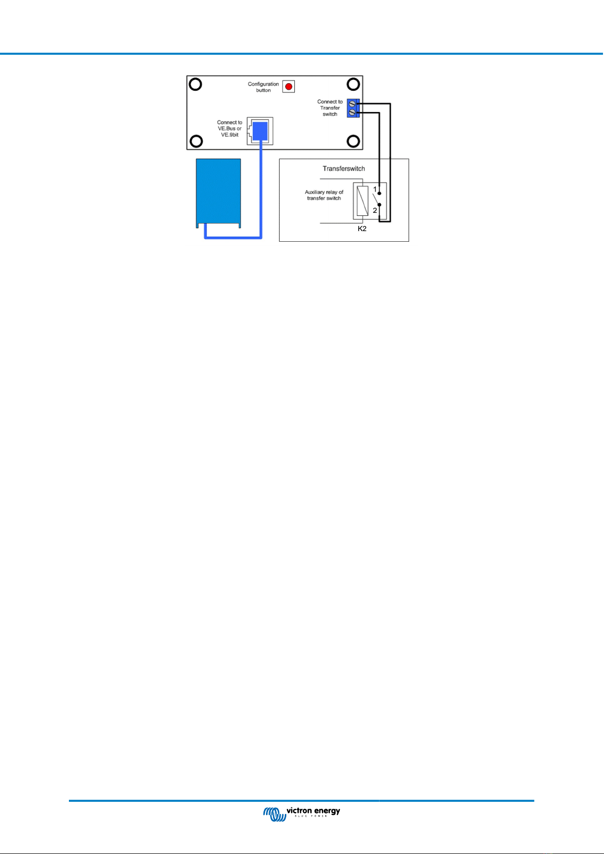
Digital Multi Control panel connection:
When the transfer switch is used together with a MultiPlus and a Digital Multi Control panel (DMC):
• Connect the transfer switch Auxiliary contact 1 and 2 of relay K2 (NO) to the screw connector on the back of the DMC as
indicated in the connection diagram below.
• When the transfer switch auxiliary contact is open, the MultiPlus current limit is controlled by the knob on the front of the DMC.
The display on the DMC will show the current limit value.
• When the transfer switch auxiliary contact is closed, a pre-set (generator) current limit is sent to the MultiPlus. The display on
the DMC will show the text: "GEN".
• For more information on this feature and on how to set the preset (generator) current limit see the Digital Multi Control Panel
manual.
VE Transfer Switch
Page 3 Installation

Connection diagram Digital Multi Control panel.
Fusing, earth leakage protection and grounding:
• The AC input and output wiring must be protected by fuses or miniature circuit breakers (MCBs) that are suitable for the
system's wire cross-section.
• External earth leakage switches (RCDs or RCCBs) must be integrated with the transfer switch wiring.
• All ground connections of the power sources and power consumers must be connected to the central ground connection of the
ship or the electric installation.
Configuration:
In most cases, there is no need to configure the transfer switch. The transfer switch is ready for use straight after installation.
However, in some specific circumstances, an adjustment of the "switch on delay" of input 1 is needed. Make the delay time
adjustment using a small flat-blade screwdriver.
VE Transfer Switch
Page 4 Installation

4. Technical specifications
VE Transfer Switch 5kVA (COS 0) 10kVA (COS 0)
Nominal voltage 200 - 250Vac, single-phase
Nominal frequency 50 – 60Hz
Nominal current input 1 20A 40A
Nominal current input 2 20A 40A
Nominal output current 20A 40A
Maximum electromotor (air-conditioner) power 1.3kW 8kW
Power consumption input 1 6VA 6VA
Power consumption input 2 0VA 0VA
Transfer time by closing contacts 10 - 20ms 10 - 20ms
Transfer time by opening contacts 5 - 20ms 5 - 20ms
Contacts delay input 1 Approximately 10s (adjustable)
Auxiliary contact 200 - 240Vac, 20A, cos phi = 1
GENERAL
Operating temperature -5°C to + 60°C
Maximum humidity (non-condensing) 95%
Miniature circuit breaker (MCB) Not included - installation dependent
Earth leakage breakers (RCD) Not included - installation dependent
ENCLOSURE
Protection category IP 54
Colour RAL 7035
Dimensions (mm) 175 x 215 x 120 175 x 215 x 120
Weight (kg) 1.85 1.65
VE Transfer Switch
Page 5 Technical specifications

5. Electrical diagram
VE Transfer Switch 5KVA
VE Transfer Switch 10KVA
VE Transfer Switch
Page 6 Electrical diagram

6. Dimensions
VE Transfer Switch 5kVA
VE transfer Switch 10kVA
VE Transfer Switch
Page 7 Dimensions
This manual suits for next models
1
Table of contents
Popular Switch manuals by other brands

HPE
HPE FlexNetwork 5130 24G 4SFP+ 1-slot HI installation guide

Eaton
Eaton MTVXKDA20225WRU Instruction booklet

Renkforce
Renkforce 2626523 operating instructions

D-Link
D-Link DGS-1016D - Switch Quick installation guide

LCN
LCN 8310-2300 Series installation instructions

NETGEAR
NETGEAR ProSafe FS750T installation guide