Metel M-MDR-40-48 User manual

www.metel.eu
1/12
Installation Manual
rev. 201606
This document contains installation instructions for the switches of the following versions:
2G-2S.0.2.F-BOX-PoE
2G-2S.0.2.F-BOX-PoE-PP
2G-2S.0.3.F-BOX-PoE
2G-2S.0.3.FC-BOX
2G-2S.3.0.F-BOX
2G-2S.1.4.F-BOX-PoE-PP
1 The package contains
1.1 Switch
1.2 Power Supply Connector
1.3 DIN Rail mounting kit
1.4 Mounting kit for wall placement
1.5 Product Datasheet which includes the Installation Manual
2 Software
The following freeware applications are available for download from www.metel.eu.
Freeware configuration software SIMULand.v4
Freeware software VcomNet for RS485 communication over virtual COM ports
USB drivers
Software is compatible with OS Windows 7, Windows 8.1 and Windows 10 (32 and 64b).

www.metel.eu
2/12
3 Mounting and Installation
The package contains two screws for a flat surface placement and a DIN holder with bolts
for parallel mounting to the DIN35 rail.
When using switches in alarm systems acc. to CSN EN 50131-1 ed.2 it is necessary to place
the switch into a distribution box with the detection of normal opening and detection of
removal from the mounting spot (from the 2nd security level).
Upright mounting to DIN35 Mounting to flat surface Parallel mounting to DIN35
4 Power Connection
For non-PoE application it is recommended to use one of the following power supplies.
Input voltage for the supplies is 230VAC ±5%.
Type
Maximal power
Operational
temperature
Output voltage
M-MDR-40-48
40W
-20°C...+70°C
48-55VDC
M-MDR-100-48
100W
-10°C...+60°C
48-55VDC
M-SDR-120-48
120W
-25°C...+70°C
48-55VDC
M-SDR-240-48
240W
-25°C...+70°C
48-55VDC
SUP-230/4870H
70W
-25°C...+50°C
48VDC
TRF-24100T
100W
-40°C...+70°C
24VAC
4.1 Power connection is explained in the figures below.
4.2 Use two 1 - 1.5 mm² wires between the power supply and the switch. It is
recommended to tin the wires or to use a compression joint before the connection.
4.3 If redundant power is required use redundant power input (see the right figure).
VDC VAC REDUNDANT SUPPLY
GND(PE)
10-60VDC
10-30VAC
10-30VAC10-60VDC
GND(PE)

www.metel.eu
3/12
4.4 For PoE application it is recommended to use one of the following power supplies.
Input voltage for the supplies are 230VAC ±5%.
Type
Maximal power
Operational
temperature
Output voltage
M-MDR-40-48
40W
-20°C...+70°C
48-55VDC
M-MDR-100-48
100W
-10°C...+60°C
48-55VDC
M-SDR-120-48
120W
-25°C...+70°C
48-55VDC
M-SDR-240-48
240W
-25°C...+70°C
48-55VDC
SUP-230/4870H
70W
-25°C...+50°C
48VDC
Recommend power supply using PoE: with PoE 0 ÷ 15 W 48 ÷ 53 VDC
with PoE 15 ÷ 25 W 52 ÷ 57 VDC
with PoE 25 –35 W 53 ÷ 57 VDC
4.5 Power connection is explained in the figures below.
4.6 If redundant power is required use redundant power input (see the right figure).
When using a redundant power supply it is necessary to ensure a difference of a min.
1V between the main and redundant power supply. The switch always takes current from
a higher voltage, and when it is disconnected the switch without interruption
automatically switches to a lower (redundant) power supply.
VDC VAC REDUNDANT SUPPLY
5 Overvoltage Protection Grounding
For correct functioning of overvoltage protections:
5.1 Switches must be grounded,
5.2 Grounding cable length should be kept as short as possible,
5.3 Ground resistance must not exceed 10 Ω. With higher ground resistance efficiency of
the overvoltage protections decreases,
5.4 Switches with protection of up to 150A are sufficiently grounded with a min. 1 mm2
wire directly into GND(PE) terminal of the supplying terminal board.
5.5 Switches with protection 1000A must be grounded using the yellow-green cable lug
included with the switch. From the lug on, the grounding cable should be at least
4 mm2 thick,
GND(PE)
PoE(PoE+)
45-56 VDC
(53-56VDC)
PoE(PoE+)
45-56 VDC
(53-56VDC)
GND(PE)

www.metel.eu
4/12
5.6 Switches can be installed only in LPZ 0B zones (lightning conductor receiver protected
outdoor areas), LPZ 1 and LPZ 2 acc. to EN 62305.
6 Fast Ethernet Port Connection
6.1 For interconnection use RJ45 connectors crimped to the cable UTP Cat5e.
6.2 UTP cable coating must be suitable to the environment in which the cable is installed.
6.3 Ports with protection of up to 1000A can be used in an outdoor environment without
any additional overvoltage protections.
6.4 Ports with protection of up to 150A can be used in an outdoor environment without
any additional overvoltage protections only for short distances up up to 10m, i.e.
within one pole etc. In the case of a longer distance, the input must be equipped with
additional overvoltage protections.
7 Gigabit Ethernet Port Connection
7.1 For interconnection use RJ45 connectors crimped to shielded cables FTP Cat6 or Cat6a.
7.2 FTP cable coating must be suitable to the environment in which the cable is installed.
7.3 Gigabit ports can be used without any additional overvoltage protections only in an
indoor environment (LPZ 1 and 2 acc. to EN 62305). In an outdoor environment (LPZ 0B
acc. to EN 62305), the input must be equipped with additional overvoltage
protections.
8 SFP Modules Connection
8.1 Insert the SFP module into the free SFP slot in the switch.
8.2 For correct functioning of the LAN-RING.v1 and .v2 systems it is essential to maintain
proper connection of the GBIC modules. Module W4 must be connected to the
miniGBIC-G1 slot and module W5 to the miniGBIC-G2 slot.
8.3 SFP modules are equipped with lasers class 1 and 1310 and 1550 nm.
WARNING: lasers can damage your sight! For this reason do not under any
circumstances look into the SFP modules that are inserted into the switch under
voltage.
8.4 Due to the wavelength multiplex apply “interconnection”, i.e. interconnect W4 to W5
(see table below).
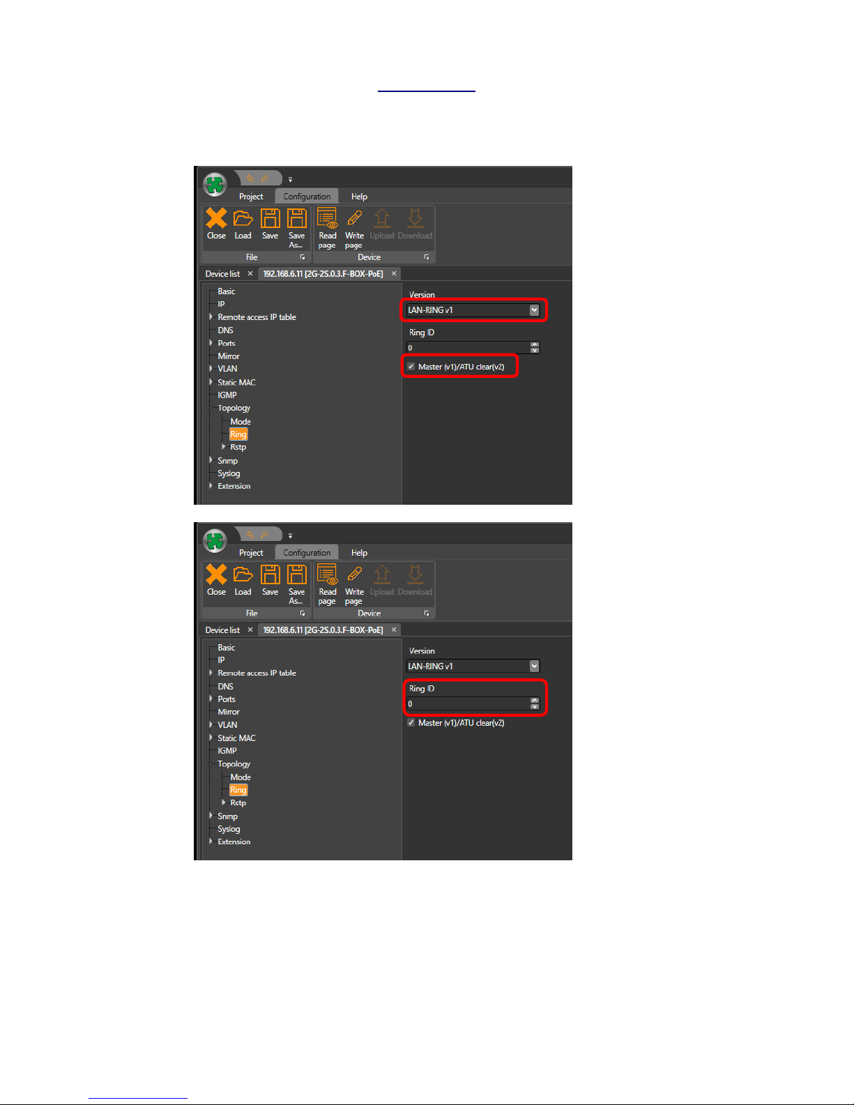
8.5 LAN-RING.v1 –before closing the optical RING there must be one switch set as
MASTER.
LAN-RING.v2 - switches with the version of firmware 54 or higher with supporting
LAN-RING.v2 will automatically set one switch as MASTER .
8.6 Proper interconnection is indicated by the GREEN LED of a port switching on.
8.7 Port activity is indicated by a blinking LED ACT.
8.8 Max. distances between ports are limited to the following table.
Note: SFP slots are 100% compatible with MSA standard. Eventual malfunction in other
manufacturers’ devices can be caused by the fact that each SFP module, regardless of
manufacturer, contains EEPROM with a whole range of module data and some switches
-Are not able to recognize modern WDM standards 100 and 1000 BASE-BX
-ignore SFP modules from other manufacturers (the name is stored in EEPROM)
etc.

www.metel.eu
5/12
Parameters of SFP modules METEL
SFP module
Fiber
Power [dBm]
Sensitivity
[dBm]
Distance [km]
BX-100-20-…
MM
(50-62.5/125 μm)
−10...0
−28
5
SM (9/125 μm)
−14...−8
−31
20
BX-1000-20-…
MM
(50-62.5/125 μm)
−10...0
−20
2
SM (9/125 μm)
−14...−8
−22
20
Parameter
Value
Unit
Note
Wavelength
W4: Tx 1310 / Rx 1550nm
nm
W5: Tx 1550 / Rx 1310nm
nm
SAFETY
WARNING: converters contain laser sources CLASS 1 according to EN60825-1-1
9 Topology
9.1 Topology Point-to-point and Bus
Switches support connection both in topology point-to-point and the optical bus. The
switches are already fully operational in the default setting and in priority SLAVE.
9.2 Topology Optical Ring
Switches support topology optical ring. Before the ring is closed it is necessary to set
a Ring ID for all switches and one switch must be in MASTER mode.
In networks with multiple rings each ring must have a unique Ring ID. For detailed
settings see the following chapters or consult the Help for SIMULand.v4 software.
For switches which support LAN-RING.v2 it is not necessary to set the priority of the
MASTER. LAN-RING.v2 automatically selects one switch as MASTER.
9.3 Topology MESH
Switch 3rd generation (with optical SFP slots) and with the FW54 and higher, support
RSTP-M (M = Metel), which is 100% compatible with RSTP / STP. In networks with
features that support RSTP-M the acceleration time of reconfiguration is tens to
hundreds of milliseconds.

www.metel.eu
6/12
10 Switch Configuration
10.1 IP Address, Mask and Gateway
10.1.1 Every switch has a pre-set default configuration with a mask 255.0.0.0 and the
IP addresses which start 10.x.x.x. Defaul IP addresses and MAC addresses are
written on the label.
10.1.2 Change the IP address if required.
10.1.3 Run application SIMULand.v4 (available on www.metel.eu)
10.1.4 Create the new project and open it. Click on the icon Search(LAN). Your
computer must have a valid IP address which is in the range used by the
switches (default: 10.xxx.xxx.xxx and mask 255.0.0.0). Please check firewall
settings if no devices were found. A new rule must be created for
SIMULand.v4 or the Firewall must be turned off.
10.1.5 Select icon „ Search(LAN) “ (Remote management)
10.1.6 Select devices for configuration and add to the device list.
10.1.7 It will now offer to download the configurations of all added devices.
Confirm the download configuration to the project by clicking on "YES".
10.1.8 After the configuration download is complete, click on "OK". You'll see a list
of devices that you have added to your project.

www.metel.eu
7/12
10.1.9 From the device list, select the switch which you want to configure and click
"Configuration".
TIP: You can also use double-click on a switch in the device list, which takes you
directly to the device configuration.
In the menu "IP" set the IP address, subnet mask and gateway.
TIP: In the quick configuration, it is possible to change the IP address, subnet mask
and gateway for all devices at one moment. More information is explained in the
manual for SIMULand.v4.
10.2 Local Management
10.2.1 Connect the device to a computer using USB-A-B cable (not included).
10.2.2 Install driver –for download from www.metel.eu
10.2.3 Verify correct port assignment in the Device manager.
10.2.4 Run SIMULand.v4 - download at www.metel.eu and create a new project.

www.metel.eu
8/12
10.2.5 Click on the “USB” icon.
10.2.6 Select the port assigned by the system and press the „Config“ button.
Continue - see Remote Management (9.1.4).
11 LAN-RING.v1
Configuration required for properly working Ring - before the optical Ring is closed!
11.1.1 For the proper functioning of the ring all switches must be connected to the ring
enabled in LAN-RING protocol.

www.metel.eu
9/12
All switches in the ring must be allowed the same protocol. LAN-RING.v1 and v2
protocol can not be used in one ring together.
One of the switches connected to the ring must be set as master "Master".
All switches in the ring must be set to the same "RING ID".
11.1.2 In applications with multiple optical rings, each ring must have (switches
connected in a ring) set to a unique RING ID –Ring Identifier (see menu
RING).

www.metel.eu
10/12
12 LAN-RING.v2
All switches in the ring must be allowed the same protocol. LAN-RING.v1 and v2 can
not be used in a one ring protocol together.
12.1.1 For the proper functioning of the ring,all switches must be connected to the ring
enabled LAN-RING.v2 protocol.

www.metel.eu
11/12
All switches in the ring must be set to the same "RING ID".
12.1.2 In applications with multiple optical rings,each ring (switches connected in a
ring) must have a unique RING ID –Ring Identifier (see menu RING).
13 RSTP
13.1.1 For the proper functioning of the RSTP enabled on the switches RSTP-M
protocol.

www.metel.eu
12/12
13.1.2 If necessary set detailed parameters of RSTP prototocol, go to the menu
Topology/RSTP/Basic and Ports.
13.2 Setting of Indication of Optical Ring Failure or Sabotage
In the case of a ring interruption in tin topology LAN-RING.v1 or v2 (failure or
sabotage) the communication is redirected in 30ms. The change of ring state (from
'loop' to 'backup') can be mapped to:
relay output on every switch,
send SNMP trap,
send an e-mail
For more information, see the Help in SIMULand.v4 software.
This manual suits for next models
5
Table of contents
Other Metel Switch manuals