INSTALLATION
10
Connect the TV Input
Depending on your TV provider source, you may connect the TV inputs in one of the
following ways:
Do You Have a Set-top Box (STB)?
1. No – Go to Connecting Directly from a Coaxial Cable below
2. Yes – Go to How Many Set-top Boxes (STB’s) Do You Have?
Connecting Directly from a Coaxial Cable:
1. Take your incoming cable or satellite coaxial cable and plug it into the “In” Port of
the supplied 1-to-2 coaxial splitter.
2. Plug the output ends of the coaxial cable into the QTV Coaxial Input using the
included short coaxial jumper cables.
3. Move on to the next section, Connect the Video Output on page 12.
How Many Set-top Boxes (STB’s) Do You Have?
1. Two (2) – Connect the two (2) included IR blasters, as shown on the left, to the
back remote receiver. There are two inputs, marked and . Place the IR
blasters/outputs over the IR receiver ports on each of the two STB’s. Go to
Connecting a Splitter below
2. Just One (1) – Connect one of the included IR blasters to back of the remote
receiver in the IR out port labeled . Then, place the blaster output over the IR
receiver ports of the STB.
After it is connected, go to How Did You Connect to the Set-top Box (STB)?
Note: You can only watch or record one show at a time until you get another STB.
Connecting a Splitter:
1. Take your incoming coaxial cable and plug it into the “In” Port of the
supplied 1-to-2 coaxial splitter.
2. Plug the 2 output coaxial cables into each cable or satellite input of the set-top
boxes (STB’s).
3. Move on to How Did You Connect the TV to the Set-top Box (STB)?
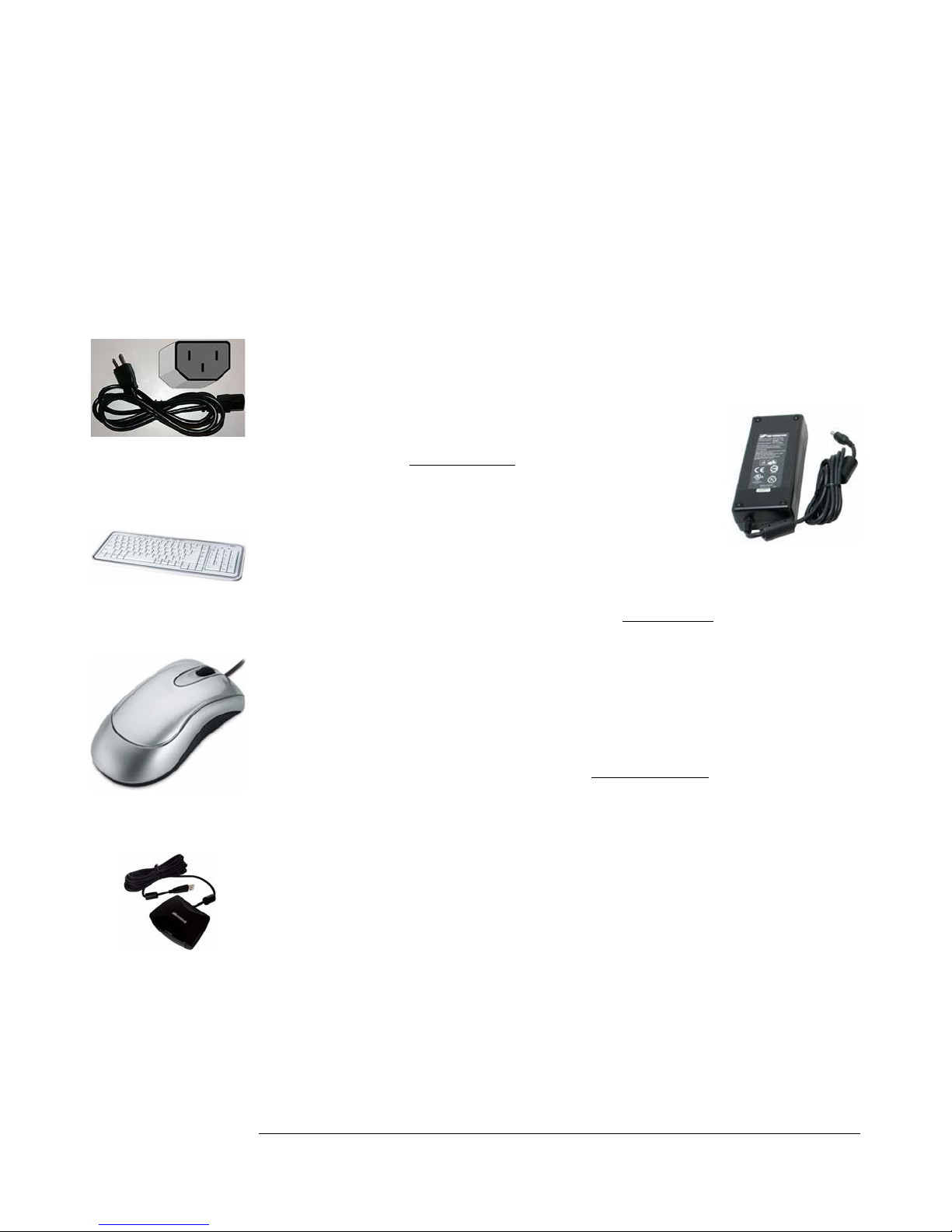
1-to-2 coaxial splitter
Looking for the
Next Section?
Look for this icon. It
denotes the start of a new
section
Included IR Blaster
Remote Receiver