Day-Night Camera Series Manual Rev.D 2013
6
WIRELESS MODELS: PRE-INSTALLATION
Site Evaluation
Identify Line-of-Sight
Although wireless video transmission may seem like a viable option for a particular application at first glance,
there are many considerations. Is there a clear, unobstructed view between the transmitter and receiver? Are
there any other devices that may cause interference? Depending on the height of the building, tower or
structure, you must consider the path that the wireless video will travel between the transmitter and receiver.
Line-of-Sight is defined as a clear and unobstructed view between the transmitter and receiver.
Up & in the Clear
To realize the optimum distance for your VideoComm Technologies wireless devices, “give them some air”. A
good rule of thumb is to mount the devices at least 15 to 20 feet above obstructions such as the roof of a
building, above parked cars in a parking lot
or the top of a fence line.
See Figure 2.
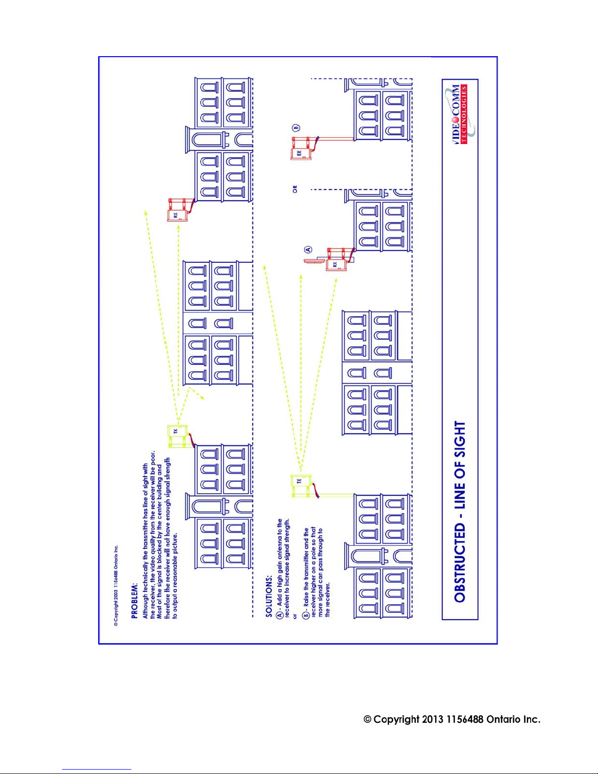
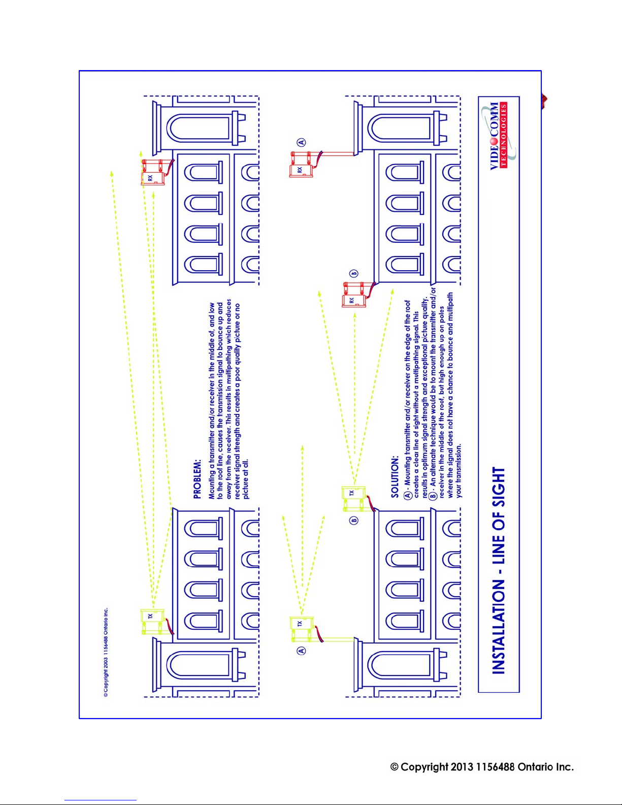
Ground Plane
If the radio devices are not mounted high enough above obstructions, the signal strength will be seriously
reduced; therefore your distance will be reduced. The signal will literately bounce up and away from your
intended target. This is known as a negative ground plane effect. The ground plane could not only be the
ground you stand on, but could also be the rooftops of cars or distant buildings. See Figure 3.If we have a
choice, place the transmitter/receiver enclosures or external antenna on the edge of the roof looking AWAY
from the building. Installing the device in the middle of the roof may cause decreased range. See Figure 4.
This is particularly important if we have a metal roof that tends to deflect signals away from the target. Also
consider any obstruction that may get in the way, like another roof or a tractor-trailer that may pass through
your “Line-of-Sight”.
Trees Grow!
If we install the video link in the winter, the leaves that come out in spring may eliminate your wireless link.
Are you trying to transmit through trees? Then you will need to seriously consider how much range will be
lost. A field test is always the best way to find out. Speak to a VideoComm Technologies Technical support
representative for a possible solution.
Unusual Traffic
Watch out for unusual traffic in your transmission path. For example, a dump truck with the back elevated
while dumping a load can be much taller than expected. Tractor-trailers or other large vehicles may be a factor
if trying to transmit over a highway. Metal obstructions between the antennas cannot be ignored including
electrical transmission lines that may not be obvious in the distance. Each high voltage wire crossing your path
can be the equivalent of transmitting past an eight-foot thick steel pipe.


 User manual")