Videocon DDB DLX User manual

SERVICE Manual
Chassis: - DDB DLX

2
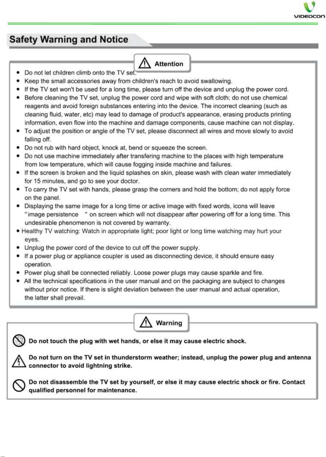
SAFETY PRECAUTIONS

3
4

2.1 General Servicing Precautions:
Always unplug the receiver AC power cord from the AC
power source before:
a. Removing or reinstalling any component, circuit board
module or any other receiver assembly.
b. Disconnecting or reconnecting any receiver electrical
plug
or other electrical connection.
c. Connecting a test substitute in parallel with an
electrolytic
capacitor in the receiver.
CAUTION: A wrong part substitution or incorrect polarity
installation of electrolytic capacitors may result in an
explosion
hazard
2. Test high voltage only by measuring it with an
appropriate high voltage meter or other voltage
measuring device (DVM, FETVOM, etc) equipped with a
suitable high voltage probe. Do not test high voltage by
"drawing an arc".
3. Do not spray chemicals on or near this receiver or any of
its assemblies.
4. Unless specified otherwise in this service manual, clean
electrical contacts only by applying the following
mixture to the contacts with a pipe cleaner, cotton-
tipped stick or comparable non-abrasive applicator; 10%
(by volume) Acetone and 90% (by volume) isopropyl
alcohol (90%-99% strength)
CAUTION: This is a flammable mixture. Unless specified
otherwise in this service manual, lubrication of contacts
in not required.
5. Do not defeat any plug/socket voltage interlocks with
which receivers covered by this service manual might be
equipped.
6. Do not apply AC power to this instrument and/or any of
its electrical assemblies unless all solid-state device heat
sinks are correctly installed.
7. Always connect the test receiver ground lead to the
receiver chassis ground before connecting the test
receiver positive lead. Always remove the test receiver
ground lead last.
8. Use with this receiver only the test fixtures specified in
this service manual. CAUTION: Do not connect the test
fixture ground strap to any heat sink in this receiver.
2.2 Electrostatically Sensitive (ES) Devices:- Some
semiconductor (solid-state) devices can be damaged easily
by static electricity. Such components commonly are called
Electrostatically Sensitive (ES) Devices.
Examples of typical ES devices are integrated circuits and
some field-effect transistors and semiconductor "chip"
components. The following techniques should be used to
help reduce the incidence of component damage caused
by static by static electricity.
1. Immediately before handling any semiconductor
component Or semiconductor-equipped assembly, drain
off any electrostatic charge on your body by touching a
known earth ground. Alternatively, obtain and wear a
Commercially available discharging wrist strap device, which
should be removed to prevent potential shock reasons prior
to applying power to the unit under test.
2. After removing an electrical assembly equipped with ES
devices, place the assembly on a conductive surface such
as aluminium foil, to prevent electrostatic charge build up
or exposure of the assembly.
3. Use only a grounded-tip soldering iron to solder or
unsolder ES devices.
4. Use only an anti-static type solder removal device. Some
solder removal devices not classified as "anti-static" can
generate electrical charges sufficient to damage ES
devices.
5. Do not use Freon-propelled chemicals. These can
generate electrical charges sufficient to damage ES
devices.
6. Do not remove a replacement ES device from its
protective package until immediately before you are
ready to install it. (Most replacement ES devices are
packaged with leads electrically shorted together by
conductive foam, aluminium foil or comparable
conductive material).
7. Minimize bodily motions when handling unpackaged
replacement ES devices. (Otherwise harmless motion
such as the brushing together of your clothes fabric or
the lifting of your foot from a carpeted floor can
generate static electricity sufficient to damage device.)
2.3 General Soldering Guidelines
1. Use a grounded-tip, low-wattage soldering iron and
appropriate tip size and shape that will maintain tip
temperature within the range or 450°F.
2. Use an appropriate gauge of RMA resin-core solder
composed of 60 parts tin/40 parts lead.
3. Keep the soldering iron tip clean and well tinned.
4. Thoroughly clean the surfaces to be soldered. Use a mall
wire-bristle (0.5 inch, or 1.25cm) brush with a metal
handle. Do not use Freon-propelled spray-on cleaners.
5. Use the following unsoldering technique
a. Allow the soldering iron tip to reach normal temperature
b. Heat the component lead until the solder melts.
c. Quickly draw the melted solder with an anti-static,
suction- type solder removal device or with solder braid.
CAUTION: Work quickly to avoid overheating the PCB.
d. Closely inspect the solder area and remove any excess or
splashed solder with a small wire-bristle brush.
2.4 Fuse and Conventional Resistor Removal/Replacement
1. Clip each fuse or resistor lead at top of the circuit board
hollows take.
2. Securely crimp the leads of replacement component
around notch at stake top.
3. Solder the connections.
CAUTION: Maintain original spacing between the replaced
component and adjacent components and the circuit board
to prevent excessive component temperatures.
5
SERVICE PRECAUTIONS
6
INTRODUCTION
DDB DELUX is a combination of MSTV59 and d2h MST5049. it supports HD panels as
well as Full HD panels. The d2h reception is High definition (HD-1080i).
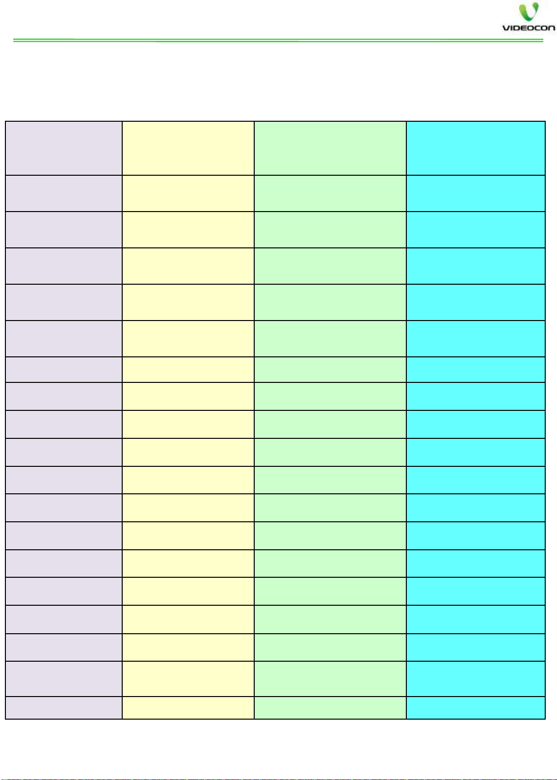
DDB FAMILY COMPARISON : CONNECTIVITY:-
Specs DDB DLX
COMBO DDB DLX NON
COMBO DDB SMART
SEG.
SUPPORTED 24” TO 32”HD 32”HD TO 55” FHD 32”HD TO 55” FHD
POWER SUPPLY Inbuilt –Combo Separate PSU Separate PSU
INBUILT d2h Yes (HD) Yes (HD) Yes (HD)
D2h SMART
CARD V-7 TYPE ONLY V-7 TYPE ONLY V-7 TYPE ONLY
D2h RESET
SWITCH YES YES YES
HDMI (VER 1.4 ) 02 NOS. 04 NOS. 03 NOS.
MULTIMEDIA USB 02 NOS. 02 NOS. 02 NOS .(01 Ver.3.0)
USB PVR Port 01 NO. 01 NO. 01 NO.
CI SOCKET YES YES YES
YPbPr 1 No 1 Mini Jack 1 Mini Jack
AV IN
01 01 Mini Jack 02 Mini Jack
VIDEO OUT
01 01 01 AV Out
EARPHONE OUT
01 01 01
RF
IN 01 01 01
ETHERNET
NA NA 01
SPDIF
OUT NA NA 01 CO-AXIAL
MEMORY
CARD
SLOT
NA NA 01 MICRO SD
Wi
-Fi SUPPORT NA NA YES INBUILT
7
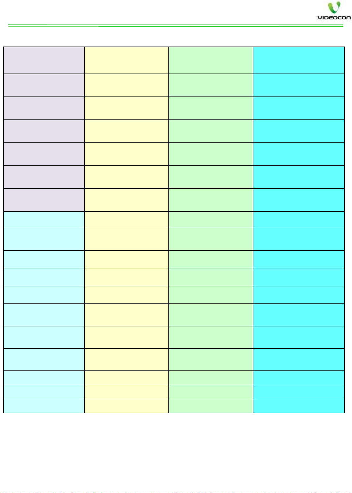
Specs DDB DLX
COMBO DDB DLX NON
COMBO DDB SMART
USB PVR YES YES YES
MHL YES (HDMI1) YES (HDMI4) YES (HDMI1)
ARC YES (HDMI2) YES (HDMI2) YES (HDMI3)
HDMI CEC YES YES YES
SOEN SOUND*YES YES YES
LIQUID LUMINOUS
** YES YES YES
SMART TV MODE NA NA YES
ANDROID
SUPPORT
NA NA YES - ANDROID 4.4.2
KITKAT
SMART UI NA NA YES
YOUTUBE NA NA YES
FACEBOOK NA NA YES
VIDEOCON APP
STORE NA NA YES
GOOGLE PLAY
STORE SUPPORT
NA NA YES
PIP
NA NA YES (IN SMART
SOURCE)
CAMERA SUPPORT
NA NA YES
Wi
-Fi HOTSPOT NA NA YES
Wi
-Fi DIRECT NA NA YES
FEATURES COMPARISON: -
*SOEN Sound: - SOEN sound may not be applicable to some models. refer the
model nomenclature for more details.
** Liquid Luminous: - LL is applicable only for Videocon models. kindly refer
the model nomenclature for more details.
8
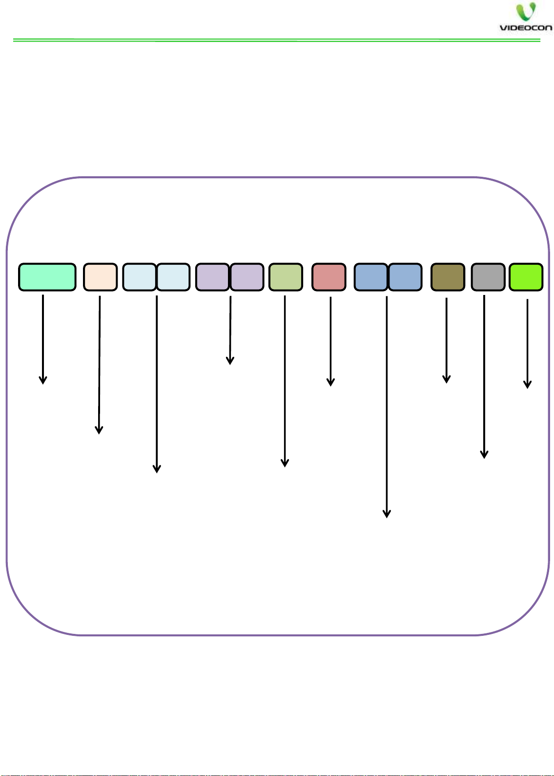
DDB / CONN MODEL DETAILS
DDB DELUX chassis is used in different models in Videocon and SANSUI brands from 24” to 55” D-
LED/ E-LED Models. The nomenclature for brands and models is as below.
Videocon model names will start with DDBTV –DDB Series.
SANSUI Model names will start with CONTV –Connect Series
The details of the model name are as below.
6 7 8 9 10 11 12 13 14 15 16 171 to 5
DDB –Videocon
CON –Sansui
V - Videocon
S - Sansui
BRAND
DDB / CON Series
MA –Con 8 with Chin
MB –BOE JL3
MC –Con 6 with Chin
KV –METAL BC VIDEOCON
KW –METAL BC SANSUI
MR –CON5 WITH DECO
KA –CON11
24”
28”
32”
40”
50”
55”
Screen SizeDistinguish
Feature
H –HD
F –FHD
Color /
Finish
H –H & C
B –BRUSH
R –red
S –Silver
Chassis
12 – DDB COMBO up to 32” only
17 –DDB Non combo 40 & above
18 – DDB Smart 32” & above
USP
X –Strata
S –Smart TV
A –Aurangabad
K - Kashipur
FactoryChanel
H –LL
F –FIM
DDBTVVMA40FH17XAH
TYPE
SEG
BRAND MODELS
(DDBTV)
FEATURES
SOEN LL SIDE
STAND SMART TV
DDB DLX
COMBO
32”
VID VMA32HH12XAH Y Y Y N
VID VJU32HH12XAH Y Y N N
VID VMR32HH12XAH Y Y Y N
SAN SMC32HH12XAF Y NY N
24” VID VJW24FH12CAH NY N N
DDB DLX NON COMBO
39”
VID VMA40FH17XAH Y Y Y N
VID VJU40FH17XAH Y Y N N
SAN SMC40FH17XAF Y NY N
VID VKA40FX17XA Y NN N
40” VID VKV40FH17XAH Y Y N N
50” VID VKV50FH17XAH Y Y N N
VID VKX50FH17FAH Y Y Y N
55” VID VKX55FH17FAH Y Y Y N
DDB SAMRT
32”
VID VMA32HH18XAH Y Y Y Y
VID VJU32HH18XAH Y Y N Y
VID VMR32HH18XAH Y Y Y Y
SAN SMC32HH18XAF Y NYY
39”
VID VMA40FH18XAH Y Y Y Y
VID VJU40FH18XAH Y Y N Y
VID VKA40FX18XA Y N N Y
SAN SMC40FH18XAF Y NYY
40” VID VKV40FH18XAH Y Y N Y
SAN SKW40FH18XAF Y NNY
50” VID VKV50FH18AH Y Y N Y
VID VKX50FH18FAH Y Y Y Y
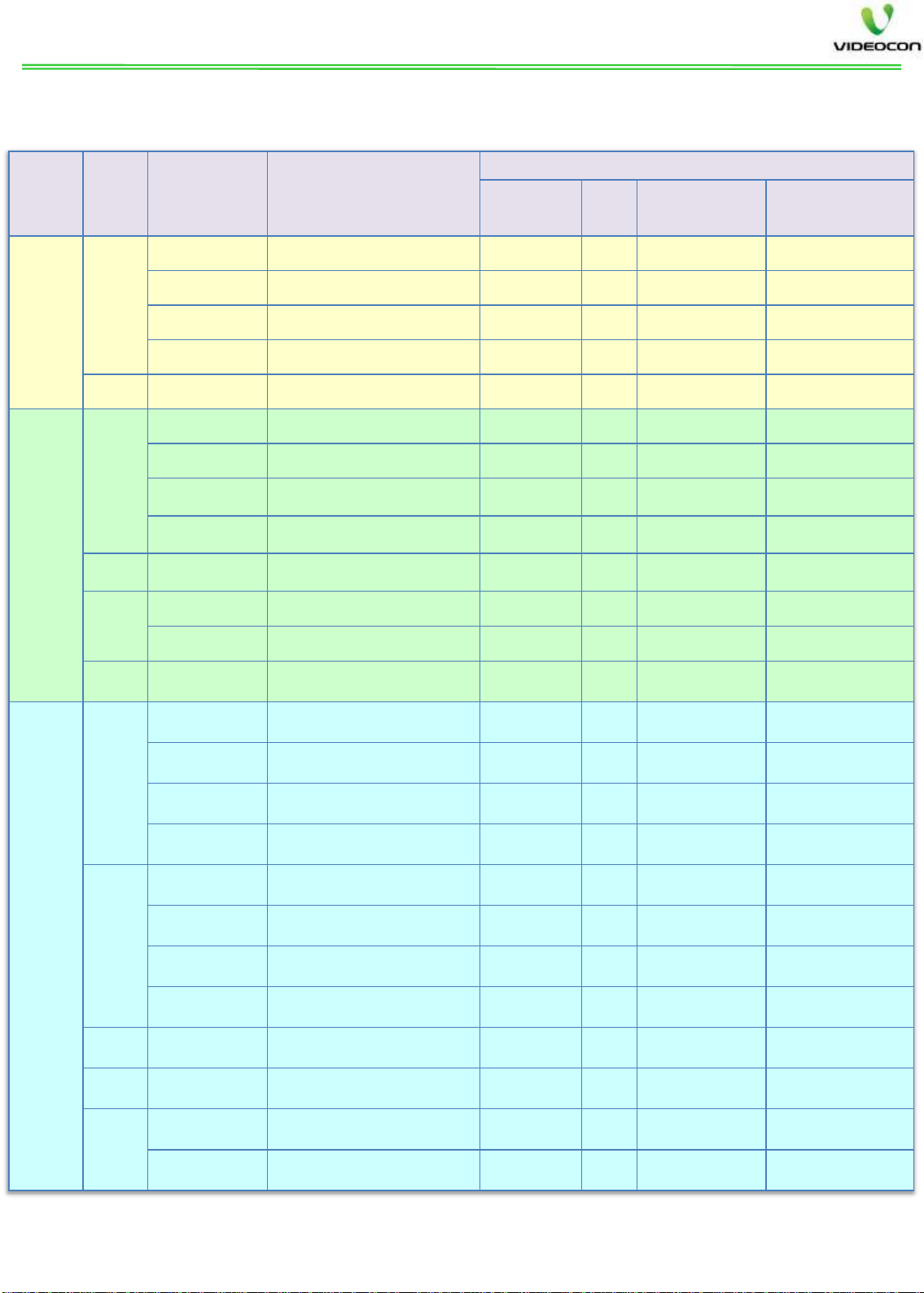
VIDEOCON & SANSUI LINEUP
9
The DDB DLX and DDB Smart current model line up is as below. The model line up may
change as per sales and marketing requirements.

10
DDB MODEL FRONT & BACK VIEW
Power LED Indicator
Front Panel Keys
Power Supply Main PCB
Other Videocon TV manuals


