manuals.online logo
Brands
  1. Home
  2. •
  3. Brands
  4. •
  5. VIDEOFIT
  6. •
  7. Digital Camera
  8. •
  9. VIDEOFIT 6050 User manual

VIDEOFIT 6050 User manual

SnapShot ANPR Bollard Camera
Model 6050 Standard Camera
Model 6070 Dual Camera
Installation Guide
SnapShot ANPR Bollard Camera Installation Guide
Page 2 of 12
About this Guide
This guide is intended for installation and
commissioning engineers who are
familiar with Videofit and SNAP ANPR
processors. It covers the installation and
testing of the standard and dual bollard
cameras. When these bollard cameras
are used in conjunction with a SNAP
ANPR processor, it is essential that the
engineer has both physical and log-on
access to the processor.
Safety Notices Used In This Manual
Important! - Indicates a potential hazard
that could seriously damage the
equipment or endanger the engineer or
subsequent user. Do not proceed
beyond these notices until you have fully
understood the implications.
Legal Notice
Camera surveillance is prohibited by law
in some countries. Check the laws in
your local region before using ANPR
cameras and associated equipment.
Liability
Every care has been taken in the
preparation of this manual. Please inform
Videofit of any inaccuracies or
omissions. Videofit cannot be held
responsible for any technical or
typographical errors and reserves the
right to make changes to the product and
manuals without prior notice. Videofit
makes no warranty of any kind with
regard to the material contained within
this document, including, but not limited
to, the implied warranties of
merchantability and fitness for a
particular purpose. Videofit shall not be
liable nor responsible for incidental or
consequential damages in connection
with the furnishing, performance or use
of this material.
Trademark Acknowledgments
SNAP ANPR is a trademark of Videofit
Limited.
Support
Should you require any technical
assistance, please contact your Videofit
or SNAP ANPR reseller.
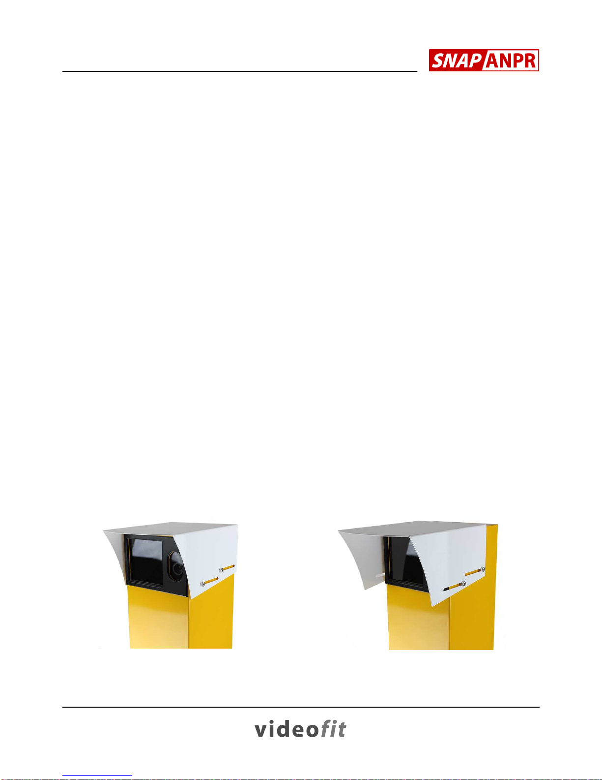
WARNING – EYE SAFETY HAZARD
Important!
These cameras do not present any
hazard in normal use. Staring directly
into the front of these camera models for
long periods at very close range should
be avoided.
SnapShot ANPR Bollard Camera Installation Guide
Page 3 of 12
1. Description
The Bollard ANPR Camera is intended for use with all Videofit and SNAP
ANPR processors although they can also be used with just a DVR if
required. These cameras are capable of very high recognition accuracy
since their free-standing design allows them to be positioned in the ideal
location for perfect plate imaging.
The main features of the cameras are:-
•Vandal-resistant design with 8mm replaceable Lexan window
•Full height lockable door for ease of installation & servicing
•Built-in pulsed infrared illumination for day and night operation
•Simple adjustment of zoom and focus
•Adjustable camera pan & tilt
The camera is also available in a dual version which includes a high
resolution colour overview camera designed to capture full colour images
of the vehicle. With these models, the overview camera is also provided
with simple zoom and focus controls.
2. Siting the Camera
The camera is designed to cover a single traffic lane only, typically 3
metres wide at the capture point. Any attempt to cover two traffic lanes
with a single camera will result in the ANPR processor missing vehicles
and mis-reading plates.
The camera should be positioned adjacent to the target traffic lane - do not
attempt to view across one lane to view another. Always try and position
the camera close to the head-on position but not exactly perpendicular to
the plate, since unwanted reflections from the infrared illuminator can
occur in some situations. The ideal angle of view is between 5º and 30º
from the normal path of the vehicles.
SnapShot ANPR Bollard Camera Installation Guide
Page 4 of 12
Vehicles should always be viewed from the front because rear plates offer
a lower success rate due to tow bars, cycle racks, winter dirt, etc. Also,
avoid locations where the camera views directly into a rising or setting sun.
If the bollard camera is to be used to view gated entrances, the camera is
best positioned adjacent to them; siting the camera further into the site
often results in viewing obstructions from the barrier arm or gates
themselves. Conversely, placing a camera in advance of the barrier is
okay, providing the cameras are not intended to open the barriers
automatically (using our Barrier Relay Controller). This is because
cameras which control vehicle barriers must view the first vehicle in the
queue for the system to operate correctly and this can only be achieved
when the cameras are adjacent to the barrier itself.
Finally, allow sufficient room behind the bollard for the door to be opened
and an engineer to work unobstructed.
Bollard Installation with Lifting Barriers
SnapShot ANPR Bollard Camera Installation Guide
Page 5 of 12
3. Fixing the Camera
The bollard camera requires a solid foundation and details of the
suggested concrete base are shown on the next page. The camera may
also be bolted to an existing concrete slab providing it is flat and of
sufficient size.
A clamping ring is provided with the camera in order to secure the cabinet
to the base. The design allows the cabinet to be rotated (panning the
camera) when the fixing bolts are slackened. For this reason, the top
surface of concrete base should be flat and level.
The base clamp ring is normally used as a template when setting rag bolts
into the base or when drilling in studs. When the studs are in situ, the
bollard cabinet is placed over them; finally, the base ring is passed through
the cabinet door, fitted over the studs and bolted down, thereby clamping
the cabinet to the concrete base.
Base Clamp Ring
Cable entry is usually through a
50mm plastic duct set within the
centre of the concrete base. On
completion, this open duct should
be sealed to prevent any
condensation within the cabinet.
If underground cable ducting is
not practical then, providing the
location permits, steel conduit
may be run at ground level to the
cabinet. Remember that the final
500mm should be run in flexible steel conduit to allow the cabinet to be
rotated. This method of cabling is best suited to locations where the bollard
is adjacent to an existing building or other structure to which the conduit
can be routed. Two conduit entry holes are provided close to the bottom of
the cabinet for this purpose.
SnapShot ANPR Bollard Camera Installation Guide
Page 6 of 12
Foundation Details
SnapShot ANPR Bollard Camera Installation Guide
Page 7 of 12
4. Connections
There are two main electrical connections to the standard bollard, namely
video and power. The dual version of the camera also has a second video
output.
Connect the incoming 24v ac supply to
the push terminals marked “24V AC
IN”. The supply should be capable of
delivering 1 amp maximum.
The video output from the ANPR
camera is always taken from the BNC
connector within the junction box.
For the Dual version of the bollard, a
second video output is provided for the
colour overview camera. This is
normally taken directly from the rear of
the overview camera itself (see below).
Note that some overview cameras have no BNC connector and a
composite cable will be pre-wired to the junction box. For these models the
overview video should be made to the BNC connector in the junction box.
Overview
zoom & focus
controls
Overview
video
connector
SnapShot ANPR Bollard Camera Installation Guide
Page 8 of 12
5. Operation
To set up and test the camera operation, please proceed as follows:-
•Connect the power and video cables and switch on the supply
•Park a vehicle at the desired captured point
•With a local video monitor, check the ANPR (and overview
camera, if fitted) are producing a picture
•Using the rotary controls on the rear of the ANPR camera (see
image below), adjust the zoom and focus for the best picture
•For Dual cameras, adjust the zoom and focus by adjustment of
the lens rings
•If you need to pan the camera, slacken the base mounting bolts
and rotate the whole cabinet. The ANPR camera may also be
tilted on its mount to provide a small elevation adjustment
•Ensure the cabinet door is closed and locked on completion
ANPR camera zoom & focus
SnapShot ANPR Bollard Camera Installation Guide
Page 9 of 12
6. License Plate Size
Below are two examples of vehicle framing with an ANPR camera. The
first is zoomed in close such that the vehicle width fills the image and
ensures the plate will be large enough to be read (the plate has been
pixelated in this image). The second image is wrongly viewing the rear of
the vehicle and needs to be zoomed in closer before the plate will be read.
Perfect Vehicle Framing Poor Vehicle Framing
Finally, here is an example of a
colour overview image taken by
the dual version of the camera.
Remember that when using these
cameras in conjunction with an
ANPR processor, the overview
image will be recorded a fraction of
a second after the plate is read
and will therefore need to be
zoomed out sufficiently to ensure
the vehicle is recorded even when
travelling at high speed.
Dual Camera Overview Image
SnapShot ANPR Bollard Camera Installation Guide
Page 10 of 12
7. Field Cables
ANPR processors requires a high quality video signal to achieve maximum
accuracy and care should be taken to ensure that the signal is not
degraded during transmission. Coaxial cable is preferred for transmitting
the video signal, although high quality passive baluns used in conjunction
with a twisted-pair cable are generally fine for cable distances up to 170
metres.
For longer cable distances, the transmission system should be designed
with great care to ensure that the video level at the receiver is close to
1vpp and that the full frequency range of the video signal is maintained. If
any form of digital conversion is used, the received analogue signal should
be at least 25fps (50fps for high speed traffic), full resolution (D1) and with
no visible compression artefacts.
With regard to the 24v ac power supply, please ensure that the conductor
size is sufficient for the length of cable run to avoid too much of a volt drop.
8. Sun Hood Adjustment
If the camera is subject to a low sun, the sun hood may be extended to
reduce glare. Remove the plastic screw caps and slacken the four
retaining screws before sliding the sun hood forward.
Sun Hood Retracted Sun Hood Extended
SnapShot ANPR Bollard Camera Installation Guide
Page 11 of 12
9. Cleaning
Keeping the window clean will help reduce image degradation. The Lexan
window is easily scratched and should not be scrubbed; just wipe once or
twice with a very wet cloth and allow to dry.
10.Specification
Model 6050 Standard Bollard 3-8 metre Zoom
6070 Dual Bollard 3-8 metre Zoom
Illuminator Pulsed Infrared
ANPR Camera Mono 620 line, 1/100,000
th
sec, 6-50mm zoom
Band Pass IR Filter
Manual control of zoom and focus
Overview Camera
(Dual Models only) Colour 560 line, 1/50
th
sec, 9-22mm zoom
Manual control of zoom and focus
Cabinet Powder coated steel, lockable full-height door, Lexan
window, rated IP54
Supply 24v ac
Power Consumption 8 watts maximum
Size 900mm x 220mm x 220mm (excluding sunhood)
Weight 22Kg
Operating Temperature -10 to 50º C
SnapShot ANPR Bollard Camera Installation Guide
Page 12 of 12
Revision 3
Copyright © Videofit Limited 2005-2013
Videofit Limited
Cheltenham
England
www.videofit.co.uk

This manual suits for next models

1

Popular Digital Camera manuals by other brands

Nikon Z 6 II manual

Nikon

Nikon Z 6 II manual

Panasonic DMC-FT2 operating instructions

Panasonic

Panasonic DMC-FT2 operating instructions

Atlantis A14-SC930-PT manual

Atlantis

Atlantis A14-SC930-PT manual

Rollei d210 user guide

Rollei

Rollei d210 user guide

Hitachi HDC-1296ER instruction manual

Hitachi

Hitachi HDC-1296ER instruction manual

Polaroid 600 Close-up instruction manual

Polaroid

Polaroid 600 Close-up instruction manual

Sony ZV-E1 Help guide

Sony

Sony ZV-E1 Help guide

Samsung Digimax A4 user manual

Samsung

Samsung Digimax A4 user manual

Evolveo StrongVision PRO A manual

Evolveo

Evolveo StrongVision PRO A manual

Sony SSC-M370 Service manual

Sony

Sony SSC-M370 Service manual

Creative PC-CAM 920 Slim user manual

Creative

Creative PC-CAM 920 Slim user manual

FujiFilm FINEPIX F810 Brochure & specs

FujiFilm

FujiFilm FINEPIX F810 Brochure & specs

Amcrest ATC-801 user manual

Amcrest

Amcrest ATC-801 user manual

AIPTEK Pencam VGA+ installation guide

AIPTEK

AIPTEK Pencam VGA+ installation guide

Vivitar ViviCam 4090 owner's manual

Vivitar

Vivitar ViviCam 4090 owner's manual

PhaseOne iXG installation guide

PhaseOne

PhaseOne iXG installation guide

Minolta DIMAGE 2300 - AUTRE manual

Minolta

Minolta DIMAGE 2300 - AUTRE manual

Nikon D300 quick guide

Nikon

Nikon D300 quick guide

manuals.online logo
manuals.online logoBrands
  • About & Mission
  • Contact us
  • Privacy Policy
  • Terms and Conditions

Copyright 2025 Manuals.Online. All Rights Reserved.