Viewpro Z10TIRM User manual

User Manual
Z10TIRM 10x Optical Zoom EO + IR Dual-Sensor Laser
Rangefinder Object Tracking Gimbal Camera
User Manual
Standard Version
标准版 快拆版
Viewport Version
For more details please scan the QR code
or visit our website:
www.viewprotech.com

Disclaimer and Warning
Legends
1.1 Introduction
1.Product Introduction
1.
Important NoteWarning
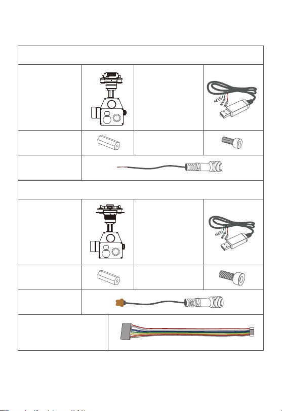
Z10TIRM is a powerful 3-axis gimbal integrated with a 10x optical
zoom SONY camera, a 19mm lens 640*480 IR thermal sensor and
a 1.5km laser rangefinder. It supports visible optical zoom, IR
thermal and visible PIP switch, IR color palette switch, photograph-
ing and video, target tracking, thermal digital zoom. When the
external GPS and time input, the OSD can display angle, zoom
times, target GPS location, target distance measured, real-time,
tracking frame, photo and video status, also can select to turn off the
OSD. It features fast focus and sensitive distance measurement.
The high-precision laser rangefinder can accurately resolve the
GPS location and distance of the object within 1500 meters. The 3
axis gimbal can achieve stabilization in yaw, roll and pitch. The
integrated design of damping system and gimbal can greatly reduce
mechanical vibration.
Z10TIRM is widely used in UAV industries of public security, electric
power, fire fighting, zoom aerial photography and other industrial
applications.
Congratulations on purchasing your new Viewpro product. Please
read this entire document carefully. Failure to read or follow instruc-
tions and warnings in this document may result in damage to your
Viewpro product. Disassemble the gimbal camera by user is not
permitted, as which may cause the camera does not work normally.
Viewpro accepts no liability for damage, injury or any legal responsi-
bility incurred directly or indirectly from the use of this project. The
user shall observe safe and lawful practices including, but no limited
to, those set forth in the manual.

1.2 In the Box
2.
A. Standard Version
B. Viewport Version
Gimbal Camera
x 1 pc
USB to TTL Cable
x 1 pc
Power Cable
x 1 pc
Gimbal Camera
x 1 pc
USB to TTL Cable
x 1 pc
M3 Screw
x 8 pcs
Copper Cylinder
x 4 pcs
Copper Cylinder
x 4 pcs
Power Cable
x 1 pc
PWM Control Cable
x 1 pc
M3 Screw
x 8 pcs
2.

2.1 Overview
TTL / S.BUS Control
Cable x 1 pc
TTL Connect Cable
x 3 pcs
Ethernet Cable x 1 pc
3.
Viewport
Control Box Back Side
(Standard Version)
(Viewport Version)
[14]
[14]
[15]
[13]
[13]
[12]
[12]
2. Installation Instruction
[1]
[7]
[8]
[2]
[3]
[9]
[10]
[11]
[5]
[4]
[6]

4.
2.2.1 Control Box Printing (Standard Version)
[1] Control box
[2] Upper damping board
[3] Lower damping board
[5] FHD zoom camera
[7] Damping ball
[8] Yaw axis motor
[9] TF card slot
[10] Roll axis motor
[11] Pitch axis motor
[12] 3-6S power interface
[13] Micro HDMI interface
[15] Viewport unlock button
[14] Ethernet interface
[6] Infrared thermal camera
[4] laser rangefinder
PITCH
Yellow Jumper Cap
TX
RX
GND
YAW
MODE
ZOOM
FOCUS
PIC/REC
MULTI
USB
AV
5V output
GND
123
Please ensure that there isn’t any obstacle while the
motor rotating.
Please remove the obstacle immediately if gimbal
camera is blocked during rotation.
Don’t put the infrared thermal camera towards the
sun in case any burn to the camera
The input voltage cannot be higher than 6S.
The pin insertion interface cannot be connected with
power supply.
The yellow jumper cap cannot be removed

Front Side
2.2.2 Control Box Printing (Viewport Version)
5.
Left Side
Right Side
PITCH
YAW
MODE
ZOOM
FOCUS/PPM
PIC/REC
MULTI
5V
GND
CVBS
3S-6S
GND
POWER PWM
GND
CANL
CANH
DC5V
GND
5V
S.BUS
TTX
GND
RXD
TXD
RX-
RX+
TX-
TX+
ETHERNET UART & S.BUS CAN

Unit: mm
2.3 Device Dimensions (Standard Version)
6.
69.8
24.5
60.0
69.7
φ3.5
167.9
110.4
33.0
69.9
128.6

Unit: mm
7.
2.3 Device Dimensions (Viewport Version)
Control Box
78.0
91.0
78.0
91.0
173.6
110.4
81.5
128.6
81.5

2.4 Install Mounting Part
8.
(1) Find out the arrow on the gimbal which indicating the yaw
heading of the payload (i.e. the lens direction when the camera
power on), and synchronize with the direction specified by the UAV.
(2) Fix one end of the copper cylinder on the screw hole of lower
damping board, and use M3 screw to fasten it.
(3) According to the provided screw hole dimension you can make
suitable mounting holes on the UAV mounting board, and fixes the
other end of the copper cylinder on the mounting board of the UAV
(Viewport version is the same).
Front

2.5 Viewport Release Instruction
9.
1. Make sure the two white stripes indicated in above picture are
aligned with each other. (If the stripes are not aligned to each other,
please pinch the connector part and turn it to left manually)
×

10.
2. Align the white dot (unlock icon) to the red triangle (below unlock
button), push the gimbal into the Viewport completely and then
rotate the gimbal camera anticlockwise.
3. When you hear "click" sound (when red dot is aligned to the red
triangle) means the gimbal camera and Viewport has been locked.
4. To unlock the Viewport, you need to press on unlock button and
rotate the gimbal camera clockwise till the white dot align to the red
triangle. Then pull the gimbal out from the Viewport.

2.6 Install TF Card
2.7 Image Output Interface
11.
TF (Micro SD card): Install the TF card to the card slot (Re. 2.1
Overview). Support max 128GB. Request Class 10 (10m/s) transmis-
sion speed or higher and FAT32 or exFAT format.
HDMI: micro HDMI output, FHD 1080P 60fps as default.
AV: no AV output
Network: Ethernet output interface, support RTSP/RTMP/UDP
video streaming. Default: RTSP output, IP address: RTSP:
//192.168.2.119:554, output resolution: 720P (record in 1080p),
frame rate: 25fps, bit rate: 2M. (Optional)
Make sure device is power off when inserting the TF
card, hot plugging is not supported.

3.1 PWM Control
12.
Control the gimbal camera functions by the multiplex pulse width
modulation signal outputted by PWM channel of the remote control
receiver. The camera needs up to 6 control channels of PWM (to
expand tracking function use up to 7 PWM channels). You can choose
needed functions according to actual usage to reduce the required
number of PWM channels.
3.1.1 PWM Connection Diagram (Connect pitch chan-
nel as example)
3. Signal Control
When using user interface software Viewlink for
network connection, the network of external device
(computer) should be the IP address: 192.168.2.2
(choose the last byte among 2~254, can not be 119
same as the gimbal), subnet mask: 255.255.255.0,
Default gateway: 192.168.2.1, and all firewalls of the
computer must be closed. Then enter the IP address
of the gimbal camera, Open Video, the video stream
can be outputted.

MULTI
PIC/REC
FOCUS
ZOOM
MODE
YAW
PITCH
13.
PWM IN
GND
5V OUTPUT
Remote Controller
Remote Controller
Connection Diagram
(Standard Version)
Connection Diagram
(Viewport Version)
Receiver
Receiver

3.1.2 PWM Control Operation Instruction
14.
1) Pitch (PWM Pitch channel in to control Pitch. Joystick, rotary knob
or 3-gear switch on remote control are optional. 3-gear switch as
example.)
2) Yaw (PWM Yaw channel in to control Yaw. Joystick, rotary knob or
3-gear switch on remote control are optional. 3-gear switch as
example.)
3) Mode (PWM Mode channel in to adjust speed control/one key to
Home position etc functions. Rotary knob or 3-gear switch on remote
control are optional. 3-gear switch as example.)
Low Gear
Pitch Up
Position 1
Middle Gear
Pitch Stop
Position 2
High Gear
Pitch Down
Position 3
Low Gear
Yaw Left
Position 1
Middle Gear
Yaw Stop
Position 2
High Gear
Yaw Right
Position 3

Function of continuous switching:
15.
3.1) Operate 1 time continuously and quickly, from position 2 - 3 - 2,
to Home position.
3.2) Operate 2 times continuously and quickly, from position 2 - 3 - 2
- 3 - 2, the camera lens looks vertically down.
3.3) Operate 3 times continuously and quickly, from position 2 - 3 - 2
- 3 - 2 - 3 - 2, to disable Follow Yaw Mode (gimbal yaw not follows by
frame)
3.4) Operate 4 times continuously and quickly, from position 2 - 3 - 2
- 3 - 2 - 3 - 2 - 3 - 2, to enable Follow Yaw Mode (gimbal yaw follows
by frame)
Position 1: Low speed mode, control pitch / yaw with this mode at
lowest speed
Position 2: Middle speed mode, control pitch / yaw with this mode at
middle speed
Position 3: High speed mode, control pitch / yaw with this mode at
highest speed
(If it is controlled by rotary knob, the speed will change according to
switch position)
Low Gear
Position 1
Middle Gear
Position 2
High Gear
Position 3

16.
4) Zoom (PWM Zoom channel in to control Zoom. Joystick, rotary
knob or 3-gear switch on remote control are optional. 3-gear switch as
example.)
5) Focus (PWM Focus channel is to control PIP / IR color palette
switch. 3-gear switch as example.)
6) Pic/Rec (PWM Pic/Rec channel in to control take picture and
record. Joystick, rotary knob or 3-gear switch on remote control are
optional. 3-gear switch as example.)
Switch from Position 2 to 1: Picture in Picture. EO+IR , IR+EO, EO
only, IR only.
Switch from Position 2 to 3: IR color switching: white hot, black hot,
pseudo color.
Low Gear
Zoom Out
Position 1
Middle Gear
Stop Zoom
Position 2
High Gear
Zoom In
Position 3
Low Gear
PIP switch
Position 1
Middle Gear
No control
Position 2
High Gear
IR color palette switch
Position 3

17.
Switch from Position 2 to 1: Take a picture
OSD display 'REC IMG' a second.
7) Multi: IR digital zoom / tracking control
Low Gear
Position 1
Middle Gear
Position 2
High Gear
Position 3
Low Gear
Position 1
Middle Gear
Position 2
High Gear
Position 3
Switch from Position 2 to 1: IR digital zoom, 1x~4x
Switch from Position 2 to 3:
Exit the tracking, display the cross cursor. Adjust the cross cursor to
lock target object and start tracking
Switch from Position 3 to 2:
Cancel tracking
Switch from Position 2 to 3: Start record / repeat operation to stop
record
Start record, the OSD display rec hh:mm:ss.
Stop record, the OSD display STBY.

3.2 Serial Port / TTL Control
Gimbal Camera Cable
18.
PC
PC
RX
GND
TX
GND
S.BUS
TTX
RXD
GND
TXD
RX-
RX+
TX+
TX-
GND
GANL
CANH
DC5V
RX (White)
TX
RX
GND
TX (Green)
GND (Black)
TTL communication requirements: TTL signal is 3.3V, baud rate:
115200, data bit 8, stop bit 1, no parity, HEX send and receive.
Control Box
Viewport Control Box
USB to TTL Cable
USB to TTL Cable
Connection Diagram Standard Version
Connection Diagram Viewport Version
Connection Diagram (PC - USB to TTL Cable- Gimbal Camera as
example):

Diagram of USB to TTL Cable:
3.3 S.BUS Control
19.
Connect the camera to the upper computer by USB to TTL cable
(Adopt connection method of TX to RX, RX to TX, GNG to GND at
Dupont ends of the provided USB to TTL cable, connect to the
specified TTL of the gimbal, and the USB end of the cable connect to
computer).
Control the gimbal camera functions by one combining signals.
Connect the external S.Bus to S.Bus port on the control box, and the
external S.bus signal GND connect to the GND interface of the control
box.
Wiring Diagram (Take Futaba remote control for example):
Install Viewlink control software to test the functions directly. Users
may choose to develop their own software, please contact technical
support for TTL control protocol file.
ViewLink is a user interface developed by Viewpro for Viewpro gimbal
cameras, you can download it from Viewpro website (www.viewpro-
tech.com) or ask distributors for installation package.
Connect serial port of gimbal to pins, DO NOT connect
with power supply.
The default baud rate of serial port is 115200, which
can be changed according to the docking equipment.
Other manuals for Z10TIRM
2
Table of contents
Other Viewpro Digital Camera manuals

Viewpro
Viewpro Z30F User manual

Viewpro
Viewpro X30TL User manual

Viewpro
Viewpro Z40K User manual

Viewpro
Viewpro Q20T User manual

Viewpro
Viewpro Z30UX User manual

Viewpro
Viewpro X30TM User manual

Viewpro
Viewpro Z-Fusion pro User manual

Viewpro
Viewpro Q20K User manual

Viewpro
Viewpro Z30TE User manual

Viewpro
Viewpro ZIR25T User manual

Viewpro
Viewpro QIR19 User manual

Viewpro
Viewpro Z40TIR User manual

Viewpro
Viewpro Z5S User manual

Viewpro
Viewpro Q10N User manual

Viewpro
Viewpro Herelink User manual

Viewpro
Viewpro Z30TL Instruction Manual

Viewpro
Viewpro Z40K User manual

Viewpro
Viewpro Z25K User manual

Viewpro
Viewpro Z40K User manual

Viewpro
Viewpro Z10N User manual