Vidikron VDP-80 User manual

USER’S GUIDE
VDP-80
Digital Video Controller / Processor

2
Warranty ............................................................................................................................................................. 3
Introduction ........................................................................................................................................................ 5
Features ........................................................................................................................................................... 5
Product Overview .............................................................................................................................................. 6
ProntoNeo Remote Control Description ......................................................................................................... 7
Controller Remote Selections .......................................................................................................................... 8
Projector Remote Selections ........................................................................................................................... 9
Installer’s Guide ............................................................................................................................................... 10
Installation ...................................................................................................................................................... 10
Front Panel ................................................................................................................................................... 10
Rear Panel .................................................................................................................................................... 11
Initial Setup — Step By Step ............................................................................................................................ 12
Input Configuration ....................................................................................................................................... 13
Miscellaneous Commands ............................................................................................................................ 14
Serial RS232 Command Interface .................................................................................................................. 16
Menu Tree ......................................................................................................................................................... 17
Hints For Optimal Picture Quality .................................................................................................................. 19
Troubleshooting ............................................................................................................................................... 20
No picture is visible: ........................................................................................................................................ 20
A PC will not drive the DVI input of the VDP-80 video processor: .................................................................... 20
Colors appear incorrect: ................................................................................................................................. 20
Specifications .................................................................................................................................................. 21
Inputs ............................................................................................................................................................. 21
Processing ..................................................................................................................................................... 21
Output ............................................................................................................................................................ 21
Miscellaneous ................................................................................................................................................. 21
Notes ................................................................................................................................................................ 22
Table of Contents

3
Congratulations on your purchase of a Vidikron video product and welcome to the Vidikron family! With proper
installation, setup and care, you should enjoy many years of unparalleled video performance.
This is a LIMITED WARRANTY as defined in the Magnuson-Moss Warranty Act. Please read it carefully and retain it
with your other important documents.
WHAT IS COVERED UNDER THE TERMS OF THIS LIMITED WARRANTY:
SERVICE LABOR: Vidikron will pay for service labor by a Vidikron Authorized Service Center when needed as
a result of manufacturing defect for a period of two (2) years from the effective date of delivery to the end user
(excluding the lamp).
PARTS: Vidikron will provide new or rebuilt replacement parts for the parts that fail due to defects in materials or
workmanship for a period of two (2) years from the effective date of delivery to the end user. Such replacement parts
are then subsequently warranted for the remaining portion (if any) of the original warranty period.
WHAT IS NOT COVERED UNDER THE TERMS OF THIS LIMITED WARRANTY:
This Limited Warranty only covers failure due to defects in materials and workmanship that occur during normal use
and does not cover normal maintenance. This Limited Warranty does not cover cabinets or any appearance items;
failure resulting from accident, misuse, abuse, neglect, mishandling, misapplication, faulty or improper installation
or setup adjustments; improper maintenance, alteration, improper use of any input signal; damage due to lightning
or power line surges, spikes and brownouts; damage that occurs during shipping or transit; or damage that is
attributed to acts of God. In the case of remote control units, damage resulting from leaking, old, damaged or
improper batteries is also excluded from coverage under this Limited Warranty.
CAUTION: THIS LIMITED WARRANTY ONLY COVERS VIDIKRON PRODUCTS PURCHASED FROM VIDIKRON
AUTHORIZED DEALERS. ALL OTHER PRODUCTS ARE SPECIFICALLY EXCLUDED FROM COVERAGE UNDER
THIS LIMITED WARRANTY. MOREOVER, DAMAGE RESULTING DIRECTLY OR INDIRECTLY FROM IMPROPER
INSTALLATION OR SETUP IS SPECIFICALLY EXCLUDED FROM COVERAGE UNDER THIS LIMITED WARRANTY.
RIGHTS, LIMITS AND EXCLUSIONS:
Vidikron limits its obligations under any implied warranties under state laws to a period not to exceed the warranty
period. There are no express warranties. Vidikron also excludes any obligation on its part for incidental or consequential
damages related to the failure of this product to function properly. Some states do not allow limitations on how long
an implied warranty lasts, and some states do not allow the exclusion or limitation of incidental or consequential
damages. So the above limitations or exclusions may not apply to you. This warranty gives you specific legal rights,
and you may also have other rights that vary from state to state.
Two Year Limited Warranty
For Video Processors and Controllers
Warranty

4
EFFECTIVE WARRANTY DATE:
This Limited Warranty begins on the effective date of delivery to the end user. For your convenience, keep the
original bill of sale as evidence of the purchase date.
IMPORTANT: WARRANTY REGISTRATION:
Please fill out and mail your warranty registration card. It is imperative that Vidikron knows how to reach you promptly
if we should discover a safety problem or product update for which you must be notified.
CONTACT A VIDIKRON AUTHORIZED SERVICE CENTER TO OBTAIN SERVICE:
Repairs made under the terms of this Limited Warranty covering your Vidikron video product will be performed at the
location of the product, during usual working hours, providing location of product is within normal operating distance
from a Vidikron Authorized Service Center. In some instances it may be necessary for the product to be returned to
the Vidikron factory for repairs. If, solely in Vidikron’s judgment, location of product to be repaired is beyond normal
operating distance of the closest Vidikron Authorized Service Center, or the repair requires the unit be returned to the
Vidikron factory, it is the owner’s responsibility to arrange for shipment of the product for repair. These arrangements
must be made through the selling Vidikron dealer. If this is not possible, contact Vidikron directly to locate an
authorized Vidikron representative who will assist you in getting a return authorization. Vidikron will return product
transportation prepaid in the United States, unless no product defect is discovered. In that instance, shipping costs
will be the responsibility of the owner.
ADDITIONAL INFORMATION:
To locate the name and address of the nearest VIDIKRON authorized service location, or for additional information
about this Limited Warranty, please call or write:
VIDIKRON
Attn.: Customer Service Department
2900 Faber Street
Union City, CA 94587
Ph: (510) 324-5900
Fax: (510) 324-5905
Toll Free: (888) 4-VIDIKRON
Warranty (continued)

5
Thank you for purchasing the Vidikron VDP-80 Video Processor. It has been designed to offer great video processing
quality, while providing the best available value. We hope you find that the Vidikron VDP-80 Video Processor exceeds
your expectations.
It is important to read and understand this manual, and the display’s specifications, before programming the Vidikron
VDP-80 Video Processor. Also, check with your Vidikron dealer for possible updates.
Features
The Vidikron VDP-80 Video Processor provides a cornerstone for the ultimate home theater experience. It is designed
to adapt to your home theater needs, rather than having the designed-in limitations commonly found in today’s video
processors. Some notable features are listed below.
• Ten inputs (2 Composite/SVideo, 2 Composite/SVideo/SD-Component, 2 SD/HD Component/RGB, 2 DVI-D,
and 2 SDI)
• Video processing/deinterlacing is supported for HDCP encrypted DVI-D inputs.
• Component/RGB analog and DVI-D input accept 720p and 1080i sources
• Transcoding (e.g. component to RGB) for digital and analog inputs.
• 3:2, 3:3 and 2:2 film pull-down frame-reconstruction for SD sources
• Per-pixel motion-adaptive video deinterlacing for SD sources
• Four independent input/output configuration memories for each input
• Black-level, contrast, calibration per memory
• Color, red-color-offset, green-color-offset calibration per memory
• Hue, red-hue-offset, green-hue-offset calibration per memory
• Y/C delay calibration with independent CB and CR delay
• Detail enhancing scaler
• Output programmable from 480p to 1080p, in scanline increments, plus 1080i
• Output width programmable in pixel increments
• Programmable output color format (SD and HD component, plus RGB)
• Programmable vertical refresh rate
• Programmable screen aspect ratio
• DVI-D output with HDCP encryption support
• BNC analog output
• Backlit infrared remote control with on-screen menu system
• RS232 serial interface for control and software-updates
• Silent operation (no fan)
Introduction

6
Product Overview
The primary functions of the Vidikron VDP-80 are to act as a
video switch, process the selected input, and output in the
appropriate format and resolution. Standard definition (SD),
enhanced-definition (ED), or high-definition (HD) video inputs
are all supported in addition to a number of PC formats. Video
inputs are converted to progressive video (if needed) and are
then scaled the video output resolution.
Interlaced video has been in use for more than 50 years and is
still the most common video format. It displays half of the lines
of picture information each sixtieth (or fiftieth) of a second.
Each half of the image is called a field and displays either all
the even lines, or all the odd lines. So, an entire image, called
a frame, takes a thirtieth (or twenty-fifth) of a second to display
on the screen. An “i” suffix on the resolution specification is
used to indicate interlaced formats.
In contrast, progressive video presents each frame as a
whole. A “p” suffix on the resolution specification is used to
indicate progressive formats. Converting interlaced video to
progressive video is referred to as “deinterlacing.”
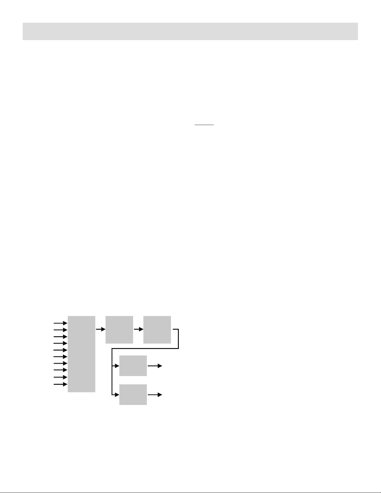
The Vidikron VDP-80 is comprised of four major functional
sections:
• Input selection, conversion to digital (if needed), and video
decoding
• Deinterlacing
• Filtering and scaling
• Conversion to analog video, or output as digital DVI-D
video.
These functional blocks are shown below.
Composite and SVideo inputs automatically select between
NTSC, PAL and SECAM formats. Component/RGB and DVI-
D inputs accept SD, ED and/or HD video at either 50 and
59.94 Hertz. HDCP encryption is supported for DVI-D inputs.
If encrypted, DVI-D inputs are decrypted, processed, scaled
and then re-encrypted for output as DVI-D (i.e not just a “pass-
through” function). The digitized data is then decoded into a
digital video format for further processing.
NOTE: HDCP encrypted DVI-D sources must be re-encrypted
for output. So, the analog output is disabled in this case. Also
the display must be HDCP capable to show these encrypted
sources. If the video input is interlaced, it is first deinterlaced
into a progressive format.
Proprietary scaling algorithms are used to scale the resulting
progressive video to the optimal size for the display. Unlike
many video processors, which are limited to a few, or even a
single output resolution, the VDP-80 is programmable from
480 to 1080 active scanlines, in scanline increments. For
analog outputs, video is over-sampled to provide the best
possible image quality. For DVI-D outputs the resolution is
programmable in both scanline increments vertically, and pixel
increments horizontally.
As part of the scaling process, digital filtering is used to enhance
the image detail. This enhancement allows standard definition
inputs, such as DVDs, to appear to be much higher resolution,
even when viewed on the large screen sizes common in home
theaters.
When the digital processing is completed, video is converted
to analog using digital-to-analog converters (DACs), or is
output as DVI-D (digital) video.
To accommodate the various video formats, the output type is
programmable. It can be set to analog YPrPb, RGBHV, RGBS
or RGsB, with programmable sync type and polarities. YPrPb
can be selected with either the SD or HD color formats. DVI-D
video can use either the “PC” range (full range black to white),
or “video range” (reduced range for black to white to allow for
blacker-than-black and whiter-than-white levels).
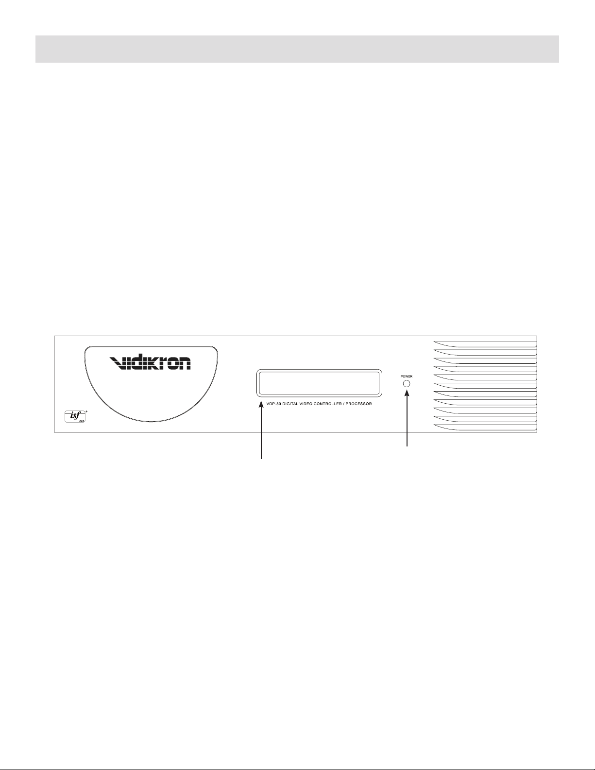
An infrared remote control, or the serial RS232 port, is used for
control and software update. Critical display setup parameters
have direct commands. Other functions use an on-screen
menu.
Every input has four independent configuration memories, to
allow options such as ISF day/night specific modes.

7
OK CH
VOL
++
--
ProntoNeo Remote Control Description
LCD Touch Screen
(see next page for screen descriptions)
Learning EyeSending LED
Serial Port for
communicating with a PC
Backlight button to activate the display
Page up button
Page down button
Content Specific buttons:
- Mode button to switch to special modes
Press and hold for 3 seconds to activate
the special mode screen
- Menu button to activate the menu screen
- Exit button to return to the previous
menu selection
- Device button to activate the device
overview
Menu Buttons:
To perform actions in the menu of a device;
ie. the on screen display of a TV or a VCR
display. Use the cursor to move up, down,
left or right in the menu and press OK to
select.
Mute
Volume Up and Volume Down button Channel Up and Channel Down button
Function Button: Can be programmed
at will. By default, it activates the Device
overview.

8
Mon Apr 05 2:06 pm
1/5 Vision 80 ctlr
VIDIKRON VISION 80
Mode Menu Exit Device
ON O FF
Aspect Ratio
Source
Menu
Mon Apr 05 2:06 pm
2/5 Vision 80 ctlr
Mode Menu Exit Device
Menu
OK
Exit
Mon Apr 05 2:06 pm
3/5 Vision 80 ctlr
Mode Menu Exit Device
ISF Night
5
ISF Day
4 6
87 9
21 3
0
Mon Apr 05 2:06 pm
4/5 Vision 80 ctlr
Mode Menu Exit Device
4:3
LETTERBOX
I-Wide
16:9
Mon Apr 05 2:06 pm
5/5 Vision 80 ctlr
Mode Menu Exit Device
VIDIKRON
2900 Faber St.
Union City, Ca 94587
www.vidikron.com
Ph (510) 324-5900
Fax (510) 324-5905
Controller Remote Selections
ON: Press to turn Controller on
OFF: Press to turn Controller off
Aspect Ratio: Press to select the Aspect Ratio screen
Source: Press to select the Source screen
Menu: Press to select the Menu screen
▲▼◄►: Navigates you in the direction of the arrows
OK: Press to enable sub menu of highlighted selection
Menu: Press to select the Menu screen
Exit: Press to return to the previous menu selection
0-9: Select to go to corresponding input
ISF Night: Press to select the stored configuration
of this memory
ISF Day: Press to select the stored configuration
of this memory
4:3: Press to select 4:3 aspect ratio
LETTERBOX: Press to select LETTERBOX aspect ratio
I-Wide: Press to select I-Wide aspect ratio
16:9: Press to select 16:9 aspect ratio
Vidikron Information Screen
Content Specific Buttons
Mode: Hold this button down for 3 seconds to go into
“Special mode” screen
Menu: Press to select the Menu screen
Exit: Press to return to the previous menu selection
Device: Press to choose between controller or projector
control

9
Mon Apr 05 2:06 pm
1/3 Vision 80 Pro
Mode Menu Exit Device
VIDIKRON
VISION 80 PROJECTOR
ON
MENU
OF F
Mon Apr 05 2:06 pm
2/3 Vision 80 Pro
Mode Menu Exit Device
Menu
Enter
Mute
Exit
Mon Apr 05 2:06 pm
3/3 Vision 80 Pro
Mode Menu Exit Device
VIDIKRON
2900 Faber St.
Union City, Ca 94587
www.vidikron.com
Ph (510) 324-5900
Fax (510) 324-5905
Projector Remote Selections
Vidikron Information Screen
ON: Hold this button down for 2 seconds to
turn Projector on
OFF: Hold this button down for 2 seconds to
turn Projector off
Menu: Press to select the Menu screen
▲▼◄►: Navigates you in the direction of the arrows
Enter: Press to enable sub menu of highlighted
selection
Menu: Press to select the Menu screen
Exit: Press to return to the previous menu selection
Mute: Press to mute the on-screen image
Content Specific Buttons
Mode: Hold this button down for 3 seconds to go into
“Special mode” screen
Menu: Press to select the Menu screen
Exit: Press to return to the previous menu selection
Device: Press to choose between controller or projector
control

10
Installer’s Guide
Installation
Unpack the shipping container. Save the container and packing
materials incase they are needed later. Place the Vidikron VDP-80
Video Processor on a component shelf and connect as described
in the Rear Panel section. The cooling vents must be clear of
obstructions to provide for convection cooling.
Install two AAA batteries in the remote control.
The following items should be included:
Vidikron VDP-80 Video Processor
Infrared remote control
External power supply
User manual
License agreement
Warranty card
Rack-mount ears.
Front Panel
The front panel has an Light-Emitting-Diode (LED) indicator light,
which can show command activity (default), or be used as a
“power-on” light (user selectable). When the LED is set to “activity” it
illuminates for a short time after commands are received. When the
LED is set to “power” it stays illuminated as long as the VDP-80 is on,
turning off briefly when a command is received.
The front panel is shown below.
LCD Display with Backlight
Power

11
The “Y” Cable (supplied) must be used for proper operation. The “Y” Cable may be extended with a standard serial cable.
A null-modem cable should not be used to extend or substitute for the “Y” Cable.
The connections are:
• RS-232: Used for software updates and control.
• POWER: Connect to supplied external 5 Volt DC power supply.
• DVI-I Video output: Provides digital (DVI-D) video output.
• INPUT 1 to INPUT 10: Standard input connections.
Input 1 and 2: DVI-D with HDCP support
Input 3 and 4: SD/HD Component, or RGB
Input 5 and 6: SVideo or Composite (selectable)
NOTE: When Input 3 or 4 is used for RGB connection, Input 5 and 6 function as the H and V Input to correspond with RGB Input 3 and 4.
Input 7 and 8: SD Component, SVideo or Composite (selectable)
Input 9 and 10: SDI (Serial-Digital-Interface)
NOTE: The Analog Video output is disabled. It reserved for future use only.
• Analog Video output: Provides analog RGB or component video output. The RS232 serial port allows the use of an external home
theater RS232 controller. This is the same as a PC DB9 serial port, except no “flow-control” is used. For updates, connect to the PC
using a DB9-F to DB9-F null-modem cable. Consult your Vidikron dealer for information on video cables.
Rear Panel
All connections are made on the rear panel, which is shown below. You must use the supplied “Y” Cable for both the projector/controller
RS-232 communication interconnection (to send commands from the controller to the projector) and for RS-232 system automation
control connections. The projector/controller operation will not function properly without this special connector, regardless of whether an
automation control system is used in the installation or not.
The short cable is always used to connect the VDP-80 Controller/Processor to the Vision Model 80 projector. If the home theater installation
includes an automation system control box, the longer cable is used for connection to it.
Short Cable
Long Cable
“Y” Cable
DVI Cable
Projector Input Panel
Controller Input Panel
Crestron/AMX
Type Automation
Control Unit
Installer’s Guide (continued)

12
Initial Setup — Step By Step
The VDP-80 remote-control setup sequence for typical configurations
is shown below. For MENU commands, buttons are shown in bold.
Press the MENU button, use arrow keys to select the next entry
and press the OK button. An “→” denotes next menu level. Not all
options are shown here. See the Installation Commands section for
additional options.
Proper setup and installation of the VDP-80 Controller assumes
the installer/technician is trained in ISF procedures and/or familiar
with them.
All picture adjustment parameters such as color balance, gray scale,
etc. should be performed following prescribed ISF standards and
procedures, using appropriate test discs, test patterns and measuring
equipment. This is vital to achieving optimal picture quality.
First, familiarize yourself with the operation of the included Vidikron
ProntoNeo remote control included with the system - see page 7.
The remote is factory programmed to operate both the VDP-80
Controller and the Vision Model 80 projector.
NOTE: The very first time you power on both units, you must power up the
projector using the projector power controls. Following that, each subsequent
startup can be accomplished by simply turning on the VDP-80 Controller,
which will in turn, automatically power up the projector as well.
In the event of a power outage, repeat the above steps to reprogram
the VDP-80 to power up the projector.
● Connect video cables. Then connect power using the supplied external
AC/DC power supply and turn all required components on.
To begin, the first step is to determine which inputs on the VDP-
80 will be used and what type of signals will be supplied to each
input.
Inputs 1 and 2 (DVI) and 3 and 4 (RGBHV/Component) are dedicated
to HD signals only.
Inputs 5 through 8 are intended for interlaced SD material.
Please note that if you are using an RGBHV input, the RGB portion
is connected to input 3 or 4, and the HV portion in this case is
connected to input 5 or 6. RGBHV inputs would use either inputs
3 and 5 together, or 4 and 6 together. The input type selection for
inputs 5 and 6 would be set to RGBHV.
To select:
MENU → INPUT → ISF DAY/NIGHT → SOURCE TYPE.
IN1 ISF NIGHT
INSTALLATION
OPTIONS
SAVE SETTINGS
SOURCE TYPE
IMAGE ADJUST
COPY SETTINGS
VISION 80
The installing technician defines the input selections as well as
determining ISF picture calibration parameters.
Once the inputs have been determined, the appropriate input
type should be programmed into the VDP-80 for each input in use
following this procedure:
● Select the input type for both component/RGB inputs (Select
desired input, then press MENU → INPUT# ISF DAY/NIGHT →
SOURCE TYPE → (TOGGLE TO CORRECT TYPE), OK
After the appropriate inputs have been selected and the input types
have been entered into the VDP-80, you can proceed to calibrating
the proper ISF Day/Night settings for each input in use and for each
aspect ratio used with those inputs.
IMPORTANT!!
Please keep in mind that all calibration adjustments made to the VDP-80
are held in temporary memory. There are four discrete memories available
for each inputs. Once you have completed the calibration procedures for all
inputs, you must select “SAVE SETTINGS” in the main menu, or all settings will
be lost when you power down the unit!
● Set the video input levels. If unsure, use defaults. The commands
are:
For analog inputs:
MENU-INPUT → ISF DAY/NIGHT → IMAGE ADJUST →
INPUT ADJUST → VIDEO LEVEL → 7.5 IRE/0 IRE
For DVI-D inputs:
MENU-INPUT → ISF DAY/NIGHT → IMAGE ADJUST →
INPUT ADJUST → VIDEO LEVEL → VIDEO/PC
Brightness and Contrast Adjust
NOTE: For the first input calibrated use the display’s black-level and contrast
adjustments. Then use these VDP-80 controls to correct for differences
between inputs.
To set the black-level (also referred to as brightness) and white-level
(also referred to as contrast) using the VDP-80 controls, go to:
MENU → INPUT# ISF DAY/NIGHT → IMAGE ADJUST →
PICTURE ADJUST → BRIGHTNESS/CONTRAST
Copy Input Settings
Copy the input setup (contrast, etc.) from the active memory,
to the selected memory, or memories. Copying the first input
memory calibrated to other memories and inputs can speed up the
calibration process. The command format is:
MENU → INPUT# ISF DAY/NIGHT → COPY SETTINGS
Installer’s Guide (continued)
PICTURE ADJUST
INPUT ADJUST
INPUT NAME
DVI SETUP
BRIGHTNESS
CONTRAST
COLOR SETTINGS
CHROMA FILTER

13
Color Settings
NOTE: Set the display’s Color and Hue to their default values.
During color calibration it is also possible to access the service menu
for WHITE BALANCE calibration.
MENU → 8 → 6 → 4 → 2 → ISF INPUT# DAY/NIGHT
→ IMAGE ADJUST → PICTURE ADJUST → WHITE
BALANCE
Once you have calibrated white balance levels, save the settings. To
exit this service menu you must then power off the VDP-80. When
you power back on the service menu will no longer be accessible.
For SD inputs 3 and 4 only, it is possible to have the VDP-80 perform
an auto calibration for white balance.
Select menu-0-9-6-6 to access this function. Upon completion, the
unit will give you an exit option from this menu.
NOTE: Auto calibration will only work properly if you are feeding the input a
“100 IRE WINDOW” during this process. Failure to do so will result in incorrect
settings.
IRE LUMA RED GRN BLU DEFAULT
100 100.0 100.0 100.0 100.0
Follow ISF color setup procedures using appropriate test discs and
test patterns.
To access color adjustment parameters:
MENU → INPUT# ISF DAY/NIGHT → IMAGE ADJUST
→ COLOR SETTINGS → (COLOR, TINT, COLOR RED,
TINT RED, COLOR GREEN, TINT GREEN)
Chroma Filter
Some digital video sources, such as DVD players, have an error in
design that affects the color (Chroma) video quality. The Chroma
filter can be enabled to mitigate this error. For high quality sources
that do not have the Chroma artifact, disabling the Chroma filter
may increase Chroma resolution. The Chroma filter is off by default.
The command format is:
MENU → INPUT# ISF DAY/NIGHT → IMAGE ADJUST →
PICTURE ADJUST → CHROMA FILTER → ON/OFF
Y/C Delay
Adjust the horizontal Chroma timing in relation to Luma. The CB
and CR channels are adjusted separately.
MENU → INPUT# ISF DAY/NIGHT → IMAGE ADJUST →
INPUT ADJUST → Y/C DELAY
Sharpness
This command is used to adjust the sharpness for the composite
and SVideo inputs. It is almost always best to leave this at the factory
default setting. The command format is:
MENU → INPUT# ISF DAY/NIGHT → IMAGE ADJUST →
SHARPNESS
Video Level
This command specifies if an analog input has a black pedestal. For
DVI inputs, it specifies if the DVI video uses video levels or PC levels.
For analog inputs:
MENU → INPUT# ISF DAY/NIGHT → IMAGE ADJUST →
INPUT ADJUST → VIDEO LEVEL → 7.5 IRE/0 IRE
For DVI input:
MENU → INPUT# ISF DAY/NIGHT → IMAGE ADJUST →
INPUT ADJUST → VIDEO LEVEL → VIDEO/PC
Input Name
Each input configuration memory can be named. Follow the on-
screen directions. The ◄ and ► arrows select which input to change
and then which character to change. The ▲ and ▼ arrows change
the selected character. The command format is:
MENU → INPUT# ISF DAY/NIGHT → IMAGE ADJUST →
INPUT ADJUST → INPUT NAME
Serial-Digital-Interface Video Inputs
The Serial-Digital-Interface (SDI) inputs provide two additional
digital connections for a DVD, and/or other source, equipped with
an SDI output. The setup is similar to other inputs, except SDI does
not require some of the setup controls used for other inputs. The
SDI input is set for a default cable length of ≤10 meters. If a longer
cable is used, enable the SDI cable equalization as follows:
MENU 0 9 7 4 Toggle SDI cable equalization (default is off)
Input Configuration
Calibrate the DVD input first, and copy that configuration to all the
other configuration memories (see the Copy Input Settings section).
Then calibrate the other inputs.
To program an input memory, select the input, then select the
configuration memory and use the menu system to configure. Each
of the four input configuration memories is independent. So, for
example, if memory A for an input is to be the same as memory B
for that same input, the input configuration must be copied from
one to the other.
Component/RGB Input Type Selection
The source type must be programmed for the component/RGB
inputs (3 and 4). Select the input then program its type. For
component input mode, either the standard-definition (SD) or
high-definition (HD) color-space may be selected. The command
format is:
MENU → INPUT# ISF DAY/NIGHT → SOURCE TYPE
The analog-to-digital converter for these inputs is calibrated at
the factory. However, since source levels vary these inputs should
be calibrated with the intended source device to achieve optimal
performance. This is possible if the source is capable of displaying a
100 IRE Window Pattern. Use the “Calibrate Component/RGB Input”
command.
Installer’s Guide (continued)

14
Installer’s Guide (continued)
Standard Definition Input Type Selection
The source type must be programmed for the standard definition
inputs (5 to 8). Inputs 5 and 6 can be composite, or SVideo. Inputs
7 and 8 can be composite, SVideo, or Component. The command
format is:
MENU → INPUT# ISF DAY/NIGHT → SOURCE TYPE
Linking an Input Memory to an Output Configuration
For HD capable inputs, each memory has four resolution “sub-
memories” (PC, 480i/480p (or 576i/576p), 720p, 1080i). The PC
memory is used for any single input resolution other than those
listed above.
DVI input HDCP Capability Setting
Some DVI sources limit functionality when driving HDCP capable
devices, such as disabling their analog outputs, even though they
do not require HDCP capability. This command can disable HDCP
capability for the current DVI input memory.
NOTE: When HDCP capability is disabled, HDCP encrypted sources are not
displayed.
MENU → INPUT# ISF DAY/NIGHT → IMAGE ADJUST →
DVI SETUP → HDCP → ON/OFF
DVI input EDID Display Information
DVI sources often read the display’s capabilities directly from the
display. With a VDP-80 video processor between the display and the
source, it may be desirable to use the VDP-80 specific information,
to pass the display’s information to the source, or to not report EDID
data at all. This command selects which option to use.
MENU → INPUT# ISF DAY/NIGHT → IMAGE ADJUST →
DVI SETUP → EDID → DEFAULT/PASS/OFF
DVI input Hotplug
Each VDP-80 DVI input sends a signal (Hotplug) back to the DVI
source to inform the source to drive its DVI output. However, different
sources behave differently to the Hotplug signal. This command
selects how the VDP-80 DVI input Hotplug signal functions. The
NORM option only asserts Hotplug when the respective input is
selected. The ON option always asserts the Hotplug signal. Typically,
NORM is used to connect to an HDCP encrypted source and ON is
used to connect to a PC.
MENU → INPUT# ISF DAY/NIGHT → IMAGE ADJUST
→DVI SETUP → HOTPLUG → NORMAL/ON
Input Sizing
Input sizing can be used to compensate for source active image size
differences. The size command does not affect the video output
size or position. Rather, it affects which input pixels are captured
for processing.
Use the TOPL command to select the top-left active input pixel.
Use the BTMR command to select the last active pixel. For these
commands, the respective corner is temporarily moved toward
the center of the screen, to simplify calibration. Select the scanline
using the ▲ and ▼ arrows, and the pixel using the ◄ and ► arrows.
The command format is:
MENU → INPUT# ISF DAY/NIGHT → IMAGE ADJUST
→ INPUT ADJUST → TOPL/BTMR adjust left and right
positions with up/down arrows, adjust top and bottom
positions with right/left arrows.
Miscellaneous Commands
Side Gray Bar Level/vertical Rate
The intensity of the side gray bars that are displayed when viewing
4:3 material can be adjusted for viewing comfort and to minimize
the possibility of image burn-in.
MENU → INPUT# ISF DAY/NIGHT → INSTALLATION →
SIDE GRAY BAR LEVEL
In addition, for SD inputs 3 and 4 the vertical rate can be selected to
correspond to PAL 50Hz or NTSC 60Hz signals:
MENU → INPUT# ISF DAY/NIGHT → INSTALLATION →
VERTICAL RATE → 60HZ/50HZ
Power Management
When power is first connected the unit can be set to turn on (ON), or
it can start in standby mode (STBY). The command format is:
MENU → INPUT# ISF DAY/NIGHT → OPTIONS →
POWER MANAGEMENT → AUTO-ON/STANDBY
Power-On Message
Change power-on message. The ◄ and ► arrows select which
character to change. The ▲ and ▼ arrows change the selected
character. The command format is:
MENU → INPUT# ISF DAY/NIGHT → OPTIONS →
POWER MANAGEMENT → GREETING (ENTER
CHARACTERS FOR STARTUP GREETING)

15
Lock the Configuration
Each input configuration can be locked to prevent unintended
changes. When locked, the input selection keys function normally,
but setup parameters are fixed. The command format is:
MENU → INPUT# ISF DAY/NIGHT → OPTIONS →
LOCK → UNLOCK/LOCKED
Front Panel LCD Indicator Operation
By default the front panel LCD is illuminated for a short time after a
command. This behavior can be changed so the LCD stays on while
the unit is on. The command is:
MENU → INPUT# ISF DAY/NIGHT → OPTIONS → LCD
SETUP → BACKLIGHT → ON/OFF
In addition, the contrast of the LCD display can be adjusted for
optimum readability:
MENU → INPUT# ISF DAY/NIGHT → OPTIONS → LCD
SETUP → CONTRAST
Input Display
The front panel LCD display can also be programmed to display the
selected input if desired:
MENU → INPUT# ISF DAY/NIGHT → OPTIONS →
INPUT DISPLAY → ON/OFF
Saving the Configuration
Save
NOTE: If a save command is not executed, any changes will be lost when the
unit is put into standby power mode, or if power is interrupted.
Permanently save the current configuration. Note that, once saved,
the configuration is retained even if the unit is disconnected from
power. Configuration from previous save is retained to allow one-
level of save-undo. The command format is:
MENU → INPUT# ISF DAY/NIGHT → SAVE SETTINGS
→ SAVE SETTINGS/DEFAULTS
Installer’s Guide (continued)

16
Serial RS232 Command Interface
ASCII Remote Function
%ON Power on
$STBY Power to standby
MMENU Activate menu
! Force menu off
XEXIT Exit. Often acts as a cancel key
kOK Accept command
<enter> OK Accept command (uses the PC “ENTER” keycode)
<◄Left arrow (“less-than” key on keyboard)
>►Right arrow (“greater-than” key on keyboard)
v▼Down arrow (lower-case v, as in “vote”)
^▲Up arrow (shift 6 key on keyboard)
0 - 9 0 - 9 Enter a digit 0 through 9
n4:3 Input is 4:3 format. Use previous zoom setting
[ Input is 4:3 format. No zoom
lLBOX Input is 4:3 letter-box format (lower-case L). Use previous zoom setting
] Input is 4:3 letter-box format (lower-case L) . No zoom
w16:9 “Enhanced for 16:9 televisions” format. Use previous zoom setting
* “Enhanced for 16:9 televisions” format. No zoom
j1.85 Input is 1.85 format. Use previous zoom setting
/ Input is 1.85 format. No zoom
aMEMA Select MEMA
bMEMB Select MEMB
cMENU, MEMA Select MEMC
dMENU, MEMB Select MEMD
z Freeze-frame. Any other character resumes
Y Output type is HD color-space YPrPb (component)
R Output type is RGBHV. <enter> completes command
S Output type is RGBS. <enter> completes command
T Output type is RGsB. <enter> completes command
A Select Vertical Resolution = 480p
B Select Vertical Resolution = 540p
C Select Vertical Resolution = 600p
D Select Vertical Resolution = 720p
E Select Vertical Resolution = 768p
F Select Vertical Resolution = 840p
G Select Vertical Resolution = 1080p
I Select Vertical Resolution = 1080I
V Set Vertical Resolution (e.g. V960 <enter>, for 960p)
~ Set Vertical rate (e.g. ~5994 <enter>, for 59.94 Hz)
H Set Horizontal Rate (e.g. H45000 <enter> for 45KHz)
= Set Output aspect ratio (e.g. =178 <enter> for 16:9 displays)
The RS232 serial interface is used to enter commands using the
same command format as the infrared remote. The serial rate is
9600 BAUD with 8 data bits, no parity bit and one stop bit. No hard-
ware or software flow-control is used. The ASCII commands are:

17
Menu Tree
MENU →
IN →
TYPE → Input type as appropriate for current input
DVI Digital-Video-Interface
SDYPBPR Component using the SDTV color-space
HDYPBPR Component using the HDTV color-space
RGBHV RGB with separate Horizontal and vertical sync
RGBS RGB with separate composite sync
RGsB RGB with composite sync on green
VID Composite interlaced standard definition
SVID SVideo interlaced standard definition
SDI Serial Digital Interface
OUTSEL If output in INDEP mode, select one of 8 output configurations
CONFIG →
COLR →
BLCK Use display black for selected input
CONT Use display contrast for selected input
COLR →
COLR Color saturation (Use “blue” color bar pattern)
HUE Hue (Use “blue” color bar pattern)
COLRED Red Color saturation offset (Use “red” color bar pattern)
HUERED Red Color Hue offset (Use “red” color bar pattern)
COLGRN Green Color saturation offset (Use “green” color bar pattern)
HUEGRN Green Hue offset (Use “green” color bar pattern)
CUE Chroma-Upsample-Error mitigation filter
CTMP Grayscale and gamma calibration (Service mode only)
ADJ →
SIZE →
TOPL Position top-left of input
BTMR Scale to position bottom-left corner of input
4:3 Select 4:3 input as normal or non-linear-stretch
YC-DLY Y/C delay independently for CR and CB
SHARP Composite and SVideo inputs only.
LEVEL Black pedestal or DVI-D levels
NAME Name input memory. Follow on-screen instructions
DVI For DVI inputs, select modes
HDCP Select if DVI input reports HDCP capability
EDID Does EDID use VDP-80 values or monitor values?
HOTPLUG Does “hotplug” remain asserted when input not selected?
COPY →
ALL Copy current input memory to all input memories
ALLMEMA Copy current input memory to all MEMA input memories
ALLMEMB Copy current input memory to all MEMB input memories
ALLMEMC Copy current input memory to all MEMC input memories
ALLMEMD Copy current input memory to all MEMD input memories
1A, etc. Copy current input memory to selected input memory

18
MENU →
MISC →
LCD →
BKLGHT LCD backlight enable (VDP-80 only)
CNTRST LCD contrast (VDP-80 only)
OSD Toggle OSD-enable. Shows status when input selected if enabled
LOCK Lock or unlock the configuration.
POWR →
AUTO Unit can go to either “ON” or “STBY” when power is applied
MSG Change power-on message. Follow the on-screen instructions
TPAT Test and warm-up patterns
PATS Test patterns
WARMUP Warm-up patterns
MENU →
SAVE → Note: Unsaved changes can be discarded by going to STBY
SAVE Save current configuration to flash ROM.
UNDO Toggle between current saved and previous saved configurations
FCTRY Reset to factory defaults
Menu Tree (continued)

19
Hints For Optimal Picture Quality
● Proper calibration is as important for attaining the best picture
as are deinterlacing and scaling. If you don’t have one, purchase
a DVD setup disc, such as AVIA™, or Digital Video Essentials™ and
watch the training lessons provided. Then follow the calibration
instructions on the disc and in this manual.
● Using high-quality cables is a very important part of video qual-
ity.
● Use a power conditioner for the video source, video processor and
the display. Power line noise is at least as important an issue for
video as it is for audio.
● Use the DVI-D output if supported by the display. For analog dis-
plays, RGBHV is preferable to component.
● For display of PC generated data, such as spreadsheets, the PC
resolution should be set to match the native resolution of the dis-
play.
● Avoid running video signals through the video switch inside re-
ceivers, as these tend to degrade video quality. The rule of thumb
for a video switch is to have 10 times the bandwidth of the video
being switched. This equates to about 50 MHz for SDTV switching,
and 300 MHz for HDTV switching.
● Component inputs on some RPTVs and projectors do not work
with standard width HSync pulses. When using component video
to drive the display, if there is a “green cast” the likely cause is a
design problem in the circuitry inside the display. Changing to bi-
level sync, and/or making the HSync pulse narrower with the VDP-
80 HSync Width command (MENU 0 9 4 0) can help eliminate this
problem.
● A system’s “ground loop noise” can cause visible horizontal band-
ing. This shows as a screen-width horizontal-band of intensity
variation. Since the VDP-80 case “floats” with reference to ground,
it may need to be grounded to the video source or display using
an approximately 18-guage wire.
● Component DVD sources provide the best standard-definition
picture quality, but SVideo sources are often a bigger challenge
and therefore can show more improvement using the VDP-80.
Since for many satellite receivers, and other video sources, SVideo
is the best output, improved SVideo performance is important for
many installations.
● For standard definition programming using cable/satellite set top
boxes, it is best to have the set top output standard definition in-
terlaced video (480i or 576i). If this is not supported, use 480p out-
put for standard definition programming. This allows the VDP-80
to deinterlace and scale the video rather than the set top box.
● Each input has four configuration memories. These are memory
A (MEMA), memory B (MEMB), Memory C (MEMC), memory
D (MEMD). These memories can be used to have four indepen-
dent configurations, such as for day (bright room) and night (dark
room). For this example, the black level will be set higher for view-
ing in a bright room than for viewing in a darkened room. To use
MEMA and MEMB for day/night, first setup MEMA normally, SAVE
the settings. Then use the input copy command to copy the setup
to MEMB. Then adjust MEMB as desired.

20
Troubleshooting
Following are some common problems, along with suggestions to
help resolve them. Also, check the www.vidikron.com website for
updated troubleshooting information.
No picture is visible:
Are all components properly connected to power, outlets switched
on, and all components powered on?
Are all of the video cables connected to their respective inputs and
outputs?
Is the menu visible when the MENU button is pressed? If it is, the
problem is with the inputs. If it is not, the problem is with the output
connections or settings.
Does the display support the programmed vertical and horizontal
timings?
Is the correct output type (DVI-D, or analog) and color-space (RGB
or YPBPR) selected?
For analog output, is the correct synchronization type and polarity
selected?
For analog output, if used, are the separate horizontal and vertical
sync signals misconnected? For VGA breakout cables, the signal
order at the BNC connectors is generally red, green, blue, horizontal-
sync and vertical-sync, but this may vary.
Is the source HDCP encrypted? Then the display must have HDCP
capability.
If these steps fail to resolve the problem, contact your home theater
specialist for assistance.
A PC will not drive the DVI input of the
VDP-80 video processor:
The correct VDP-80 DVI input must be selected while booting the
PC for the PC to be able to read the EDID data from the VDP-80
video processor.
Objects appear to be too tall or too wide:
Make sure the video output aspect ratio is programmed correctly.
Make sure the correct input aspect ratio is selected.
Make sure input size is adjusted correctly.
Make sure the “television aspect ratio” setting is 16:9 in the setup
menu of all source devices that support this feature (DVD players,
satellite receivers, etc.), even if the screen is not 16:9.
Colors appear incorrect:
Is the correct output color space (RGB, SD YPBPR, HD YPBPR)
selected?
If input 3 or 4, and color have a slight color “cast”: Has the input been
calibrated using the “Calibrate Component/RGB Input” command?
Other manuals for VDP-80
3
Table of contents
Other Vidikron Media Converter manuals
Popular Media Converter manuals by other brands

Extron electronics
Extron electronics DVS 204 user guide

Optical Systems Design
Optical Systems Design OSD2166M Series Operator's manual

TBS technologies
TBS technologies TBS2600 user manual

Ocean Matrix
Ocean Matrix Professional user manual

K2L
K2L MOST150 user guide

Engler
Engler Son-Mate II instruction manual